
 Open Access Article
 This Open Access Article is licensed under a Creative Commons Attribution-Non Commercial 3.0 Unported Licence
Enhanced stability and ultrahigh activity of amorphous ripple nanostructured Ni-doped Fe oxyhydroxide electrode toward synergetic electrocatalytic water splitting†
Selvam Mathi and
Jayaraman Jayabharathi *
*
Department of Chemistry, Material Science Lab, Annamalai University, Annamalai Nagar, Tamil Nadu-608 002, India
First published on 14th July 2020
Abstract
The development of high-performance catalysts for oxygen-evolution reaction (OER) is paramount for cost-effective conversion of renewable electricity to fuels and chemicals. Here we report, highly efficient, ultra-durable and earth-abundant Ni@Fe-NP electrocatalysts developed by solvothermal method for oxygen evolution reaction (OER). The newly developed oxygen electrode show prolonged stability and high catalytic-activity in line with water oxidation keeping alkaline condition which requires overpotential of only 211 mV at current density of 10 mA cm−2. Collectively, the as-prepared amorphous Ni@Fe-NP rippled nanostructured electrode is the most effective oxygen evolution electrode in alkaline solution. Therefore, this study will offer exciting new avenues for designing self-supported electrode materials towards water splitting and other applications.
1. Introduction
The scalable production of renewable energy by electrolytic water-splitting to hydrogen fuels is an alternative for replacing conventional fossil fuels. Therefore, efficient OER catalysts are urgently required to reduce the energy barrier to enhance the energy efficiency. A large overpotential (η) is required to generate H2 which leads to slow oxygen evolution kinetics. Despite current improvement in the progress of heterogeneous-catalysts to negotiate OER (2H2O → O2(g) + 4H+(aq) + 4e−; E° (O2/H2O) = 1.23 V versus RHE; E° – standard potential and RHE – reversible hydrogen electrode)1–4 commercialization has been held up by absence of low-cost catalytic materials and also, these materials show high current densities (J) of >0.5 A cm−2 at low η of <0.3 V over prolonged time periods. Metal oxides are the most durable and active water oxidation catalysts,1,2 so far, RuO2 and IrO2 are the benchmark OER catalysts, owing to their high catalytic activity,5,6 a myriad of perovskite3,7 and spinel8 solids have shown to be efficient catalysts. The low-cost transition metal nickel–iron (Ni–Fe) composites based electrocatalyst are promising to overcome the multistep electron transfer in OER reaction.9–23 In nickel–iron composites, nickel acts as active center of oxygen evolution reaction and iron increases the electrical conductivity.24,25The enhancing catalytic activity of iron is undeniable,26–31 but it show conductivity increment of the film.17 Most of the reported OER catalyst are carbon-based powder materials which are coated on the conductive substrates such as GC or Ni foam using Nafion.32 However, these carbon based materials are unsuitable for OER due to large water electrolysis with higher positive cell voltage (2.0 V). So, it is required to develop alternative metal-rich nanomaterials as OER electrocatalyst with high activity and stable in the overall water splitting cell. Thus, amorphous nanomaterials are a new platform for the synthesis of advanced OER electrocatalyst.33 A very strong synergistic effect upon the incorporation of Fe into Ni, even in a small amount, enhanced the catalytic activity.34 Higher nickel oxidation state would be the additional beneficial to enhance the catalytic activity because increase of Ni–O bond.35–37 The Fe4+ sites are at edges or defects in NiOOH structure and enhancing the active site of the catalyst, which enhances the oxyl character and promotes O–O bond formation.38–46 Hence, the amorphous nanomaterials have moral prospects in the applications of OER since they enhanced the electrocatalytic activity while maintaining the stability.
Herein, we introduced an easy, ecofriendly and low-cost solvothermal method to produce mixed amorphous nanomaterials Ni@Fe-NP as an efficient and durable electrocatalyst for OER reaction. The solvothermal method offer amorphous nanomaterial with very high surface area, integrity, electrical conductivity and highest OER activity in alkaline solution. The prepared amorphous nanomaterial catalyst coated on the nickel foam electrode exhibits excellent OER electrocatalytic activity, long term stability with low overpotentials of 211 mV at current density of 10 mA cm−2 and had a long term conventional alkaline electrolyzer stability over 150 h at 10 mA cm−2. The outstanding OER performance of Ni@Fe-NP was close to the state of the art precious catalyst RuO2 and IrO2.
2. Experimental section
2.1 Materials and methods
KOH, glucose, Ni(NO3)2, Fe (NO3)3·9H2O, toluene and isopropanol were purchased from SAMCHUN chemicals; HCl was purchased from JUNSEI chemicals, NaBH4, CTAB, IrO2, 20%-Pt/C, Nafion® solution in lower aliphatic alcohol was purchased from Sigma Aldrich.2.2 Synthesis of amorphous Ni@Fe nanoparticles
About 1 g Fe(NO3)3·9H2O and 1 g CTAB in 40 mL water was added to 0.2 g NaBH4 in 10 mL H2O for 10 min and stirring was continued for 30 min. The formed Fe-NP was centrifuged, washed and dried under vacuum. The weight ratio of nickel and Fe-NP was determined to be 3/7, 5/5 and 7/3 by adjusting the amount of nickel(II) nitrate and Fe-NP. The aforementioned prepared Fe nanoparticles was dispersed in 20 mL DMF, a small amount of nickel precursor Ni(NO3)2 and glucose (800 mg) was added to the dispersion. Then, the mixture was sonicated for 10 min and heated to 160 °C (12 h) with stirring and cooled. The reaction mixture was centrifuged with ethanol/toluene mixture and acetone/toluene mixture and dried (60 °C for 24 h). The resulting material was brown in color suggest the formation of fine particle with amorphous Ni@Fe-NP.2.3 Characterization
The morphology of Ni@Fe-NP was determined using Hitachi S-4700 SEM (scanning electron microscope) operated at 10 kV and with EM 912 omega TEM (transmission electron microscope) operated at 120 kV. X-ray diffraction (XRD) of Ni@Fe-NP were recorded with Rigaku Smartlab diffractometer with Cu Kα radiation (1.5406 Å; 40 kV; 40 mA). The elemental composition of Ni@Fe-NP were analysed by XPS (X-ray photoelectron spectroscopy) with ESCALAB-250 spectrometer (monochromated Al Kα (150 W) source). Nitrogen adsorption–desorption isotherms were measured at −196 °C using micromeritics ASAP 2020 accelerated surface area with porosimetry system. The specific surface area was determined on the basis of Brunauer–Emmett–Teller (BET) method from nitrogen adsorption data at a relative pressure range between 0.05 and 0.2. The total pore volume was calculated from the gas adsorbed with relative pressure of 0.99 and PSD (pore size distribution) was derived from adsorption branches by Barrett–Joyner–Halenda (BJH) method.2.4 Preparation of electrode and electrochemical characterization
Using alumina slurry the working electrode was polished as mirror like surface and washed with water and acetone and dried. The slurry used was made by mixing 4.0 mg of catalyst in 1.0 mL solvent mixture (5 wt% Nafion and water (v/v – 1/9)) for 20 min in ultrasonicator. The commercially available IrO2 catalyst was used for comparison: 1.0 mg mL−1 of IrO2 suspension was prepared using identical procedure. The slurry was placed on a precleaned working electrode and the electrode was allowed to dry at room temperature before measurement. The catalyst loading of 0.5 μg cm−2 was use of the obtained (3/7, 5/5 and 7/3) catalysts or commercial IrO2. Biologic VMP work station was employed for electrochemical measurements. Both Ni@Fe-NP catalysts and IrO2 catalyst was used as working electrode directly without any other treatment. OER performances of Ni@Fe-NP electrodes were examined by OER polarization curves, chronoamperometry and EIS (electrochemical impedance spectroscopy). Electrochemical analyses were studied using three-electrode geometry. A glassy carbon was employed as working electrode, Ag/AgCl saturated with KCl and Pt wire was employed as reference and counter electrodes, respectively. The OER activity was evaluated by linear sweep voltammetry (LSV: scan rate – 10 mV s−1). The impedance of each catalyst was measured by EIS (electrochemical impedance spectroscopy-100 kHz to 10 mHz) with a sinusoidal perturbation amplitude of 5 mV.Here, the turnover frequency is rate of evolved molecular O2 per surface active site per second which can be calculated by the equation: TOF = [J × A]/[4 × F × n], where J – current density at, A – electrode surface area, F – Faraday constant (96![[thin space (1/6-em)]](https://www.rsc.org/images/entities/char_2009.gif) 485.3 C mol−1) and n – number of moles of metal on electrode. The overpotential used for the calculation of TOF is 1.6 V vs. RHE.
485.3 C mol−1) and n – number of moles of metal on electrode. The overpotential used for the calculation of TOF is 1.6 V vs. RHE.
3. Result and discussion
Fig. 1 illustrates the formation of amorphous Ni@Fe-NP. Upon fast reduction of iron nitrate using sodium borohydride, FeOH-NP was obtained. The subsequent solvothermal methods involving Ni2+ doping on FeOH-NP surface with DMF in the presence of glucose at 160 °C (12 h). The FeOH-NP was completely converted into amorphous Ni@Fe-NP according to coordinating the etching process which offers high surface area, high electronic conductivity and high stability with enhanced activity. | ||
| Fig. 1 Schematic route for amorphous Ni@Fe-NP. | ||
The Ni was selected as a stimulant for OER activity because of its electrical conductivity, catalytic property and various applications towards our electrochemical feature. The FE-SEM image confirmed the amorphous nature of Ni@Fe-NP as well as a large amount of accessible catalytic active sites (Fig. 2). Further, to understand the composition of Ni@Fe-NP amorphous nanostructure with different ratio of Ni doping, EDS elemental mapping was record which shows a homogeneous distribution of Ni and Fe throughout the electrocatalyst surface and the corresponding results are given in Fig. S1.† The rippled nanolayer of amorphous Ni@Fe-NP was formed by internally connected mesoporous with high surface area and the calculated of pore size is around 2 to 10 nm (Fig. S2†).
 | ||
| Fig. 2 SEM images (A & B) and TEM images of amorphous Ni@Fe-NP (C & D) (inset: selected area electron diffraction pattern). | ||
The amorphous nanostructured Ni@Fe-NP electrocatalyst was studied using HR-TEM (Fig. 2), which shows that all amorphous rippled layer Ni@Fe-NP was well uniformly dispersed and nickel and iron are interconnected with each other which is in line with FE-SEM result. HR-TEM revealed that the solvothermal prepared Ni@Fe-NP are amorphous rippled layered are very thin and transparent with absence of typical metal lattice fringes for iron, nickel and their composites. Selected area of diffraction pattern shows a broad diffused halo ring which confirms the solvothermal prepared Ni@Fe-NP having amorphous morphology.47 The morphology results indicate that mesoporous amorphous Ni@Fe-NP is a hierarchically structured OER electrocatalyst which is beneficial for enhanced electrocatalytic O2 evolution reaction. The XRD peak well matched with JCPDS no: 01-089-3850 (Fig. 4) and Fig. 4b–d shows different ratio of Ni-doped FeOH-NP.
The absence of additional peak formation in XRD confirms the purity of the electrocatalyst. The amorphous nature of Ni@Fe-NP catalyst can provide an abundant catalytically high active site for electrocatalytic reactions owing to their structural flexibility as well as larger density of unsaturated short-range coordination sites which gives rise to an easier O–O adsorption of reactants compared to the counterpart crystalline phases.48 The formation of the amorphous rippled nanostructured Ni@Fe NP was confirmed by high-angle annular dark-field scanning transmission electron microscopy (HAADF-STEM) (Fig. 3 and S3†) and EDX line scanning analysis (Fig. S3A and B†).
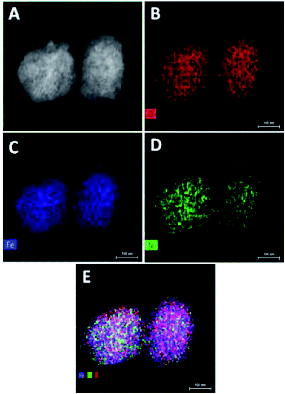 | ||
| Fig. 3 TEM elemental mapping of Ni@Fe-NP: (A) STEM image; (B) oxygen element image; (C) iron elemental image; (D) nickel elemental image and (E) overlay of all O, Fe and Ni elemental image. | ||
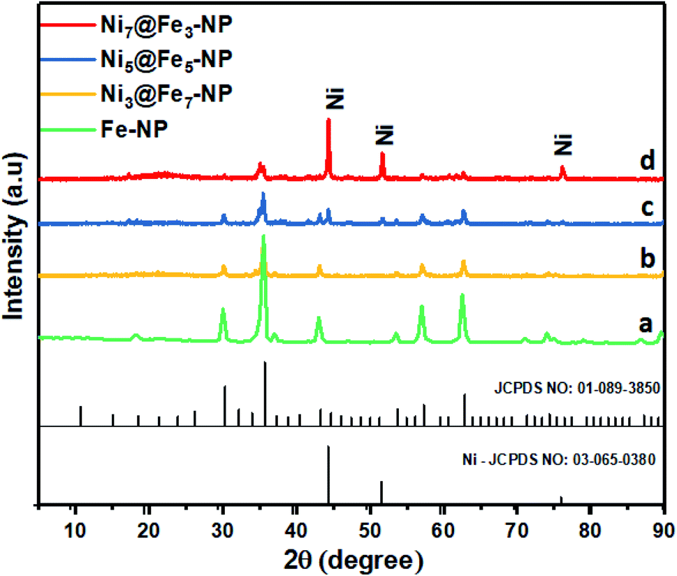 | ||
| Fig. 4 XRD pattern of FeOH-NP (a); Ni3@Fe7-NP (b); Ni5@Fe5-NP (c) and Ni7@Fe3-NP (d). | ||
The intensity of nickel is higher than that of iron and oxygen in the center of amorphous nanoparticles which indicate that the small amount Ni atoms are homogeneously distributed at the interior of the amorphous nanoparticles; Ni atoms are mainly distributed in the inner surface of Fe whereas Fe–OH atoms coexist at the outer surface which confirm the amorphous nature of Ni@Fe-nanoparticles. The composition of Ni@Fe-NP was determined by XPS; typical fitted Ni, Fe and O XPS spectra of Ni@Fe-NP obtained using the Gaussian fitting method (Fig. 5). The Ni, Fe and O was detected in the XPS spectrum with bimetallic composition. The high-resolution Ni 2p spectrum can be fitted into two spin–orbit peaks of Ni 2p3/2 and Ni 2p1/2 along with the corresponding shake-up satellites (Fig. 4b). The peaks are mainly fitted by two Ni environments: Ni2+ at 853.7, 855.1, 872.7 eV and Ni3+ at 856.2, 874.4 eV, respectively with 17.6 eV spin-energy difference which is the characteristic of M(OH)2 phase.49,50 The Fe XPS shows peaks at 710.6 and 724.4 eV corresponds to Fe 2p3/2 and Fe 2p1/2, respectively (Fig. 3A). After fitting, the peaks at 712.3 and 726.8 eV corresponds to Fe 2p3/2 and Fe 2p1/2 of Fe–OH in Ni@Fe-NP, respectively.51,52 The high-resolution O 1s spectrum (Fig. 4c) can be deconvoluted into three peaks at 529.7 (O 1), 530.9 (O 2) and 532.0 eV (O 3) and can be attributed to lattice oxygen species (O2−)53,54 and hydroxyl groups (–OH) or the surface adsorbed oxygen in Fe21HO32. The FT-IR was carried out for Ni@Fe-NP sample to confirm the Ni–Fe hydroxide formation (Fig. 4d). The presence of broad peak around 3636 cm−1 corresponds to the non-hydrogen bonded O–H, broad shoulder peak at 3428 cm−1, suggesting that the presence of hydroxide and oxy hydroxide species.
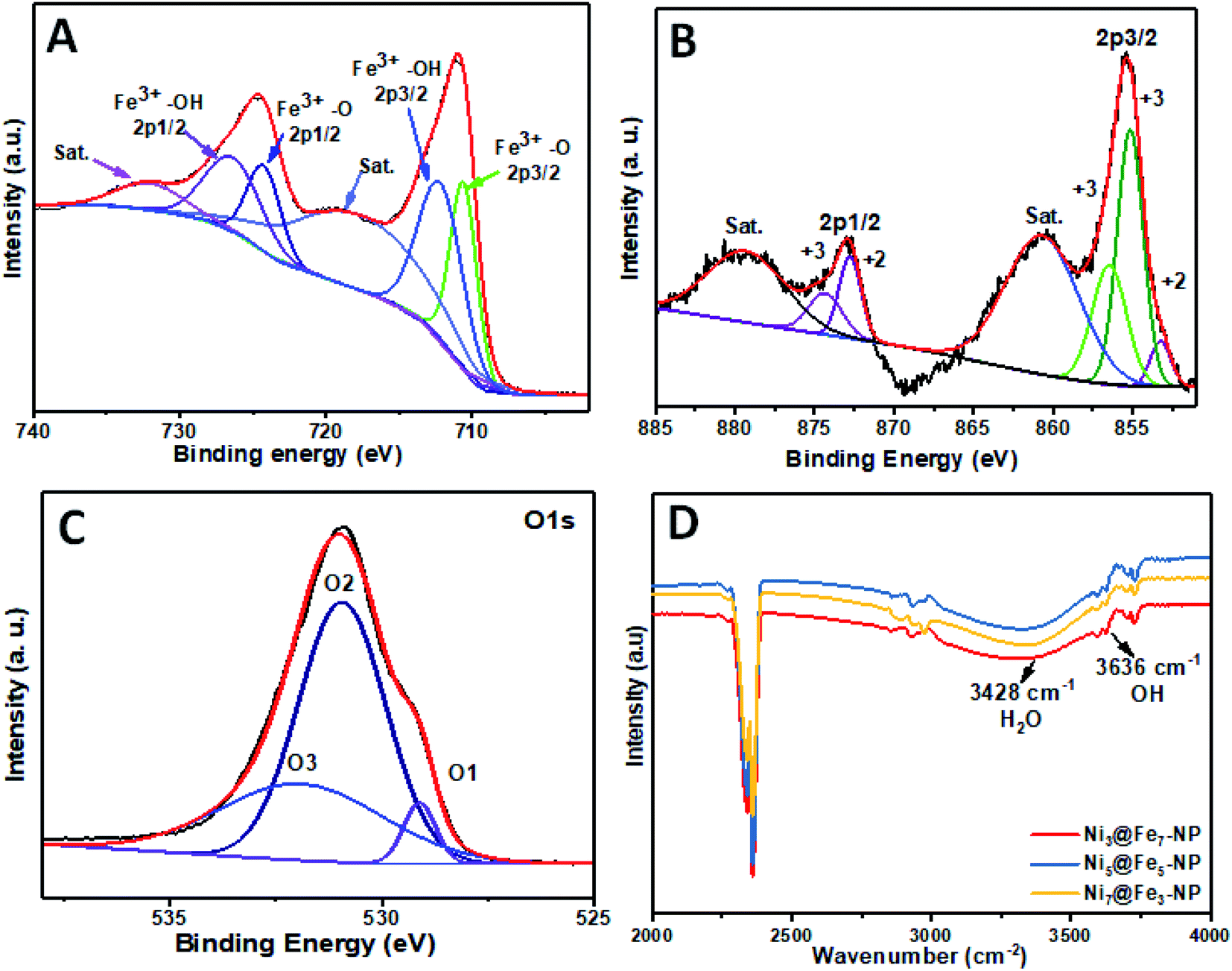 | ||
| Fig. 5 High-resolution XPS spectra of (A) Fe; (B) Ni; (C) O and (D) FT-IR spectra of Ni@Fe-NP. | ||
3.1 Electrochemical activity
The electrochemical OER activity of Ni3@Fe7-NP, Ni7@Fe3-NP, Ni5@Fe5-NP and IrO2 was first evaluated by using homogeneously coated on GC electrode in the three electrode system. The OER polarization curves were harvested from LSV (linear sweep voltammogram) with potential range 1 to 1.8 V versus RHE in 0.1 M KOH (Fig. 6). The Ni3@Fe7-NP electrocatalyst requires an overpotential of 361 mV (without iR correction) to afford 10 mA cm−2 which is a matric apt solar fuel synthesis55 (thermodynamic OER potential – E0 H2O/O2 −1.229 V). However, the electrocatalysts Ni7@Fe3-NP and Ni5@Fe5-NP requires the overpotentials of 411 and 381 mV, respectively at 10 mA cm−2 which is smaller than that of commercial IrO2 (511 mV) and RuO2 anode electrocatalyst at 10 mA cm−2 (Fig. 6A). The Tafel graph shows the slope value for Ni3@Fe7-NP and IrO2 coated on GC as 98.9, 106 and 130 mV dec−1, for GC (Fig. 6B). The low Tafel slope of Ni3@Fe7-NP signified the superior reaction kinetics in the OER. The Ni3@Fe7-NP undergo the OER reaction mechanism as given below equation:| MOOH + OH− → MO(OH)2+ e− | (1) |
| MO(OH)2+ OH− → [MO(OH)2]+ + e− | (2) |
| [MO(OH)2]+ + 2OH− → [MO]+ + O2+ 2H2O + 2e− | (3) |
| [MO]+ + OH− →MOOH | (4) |
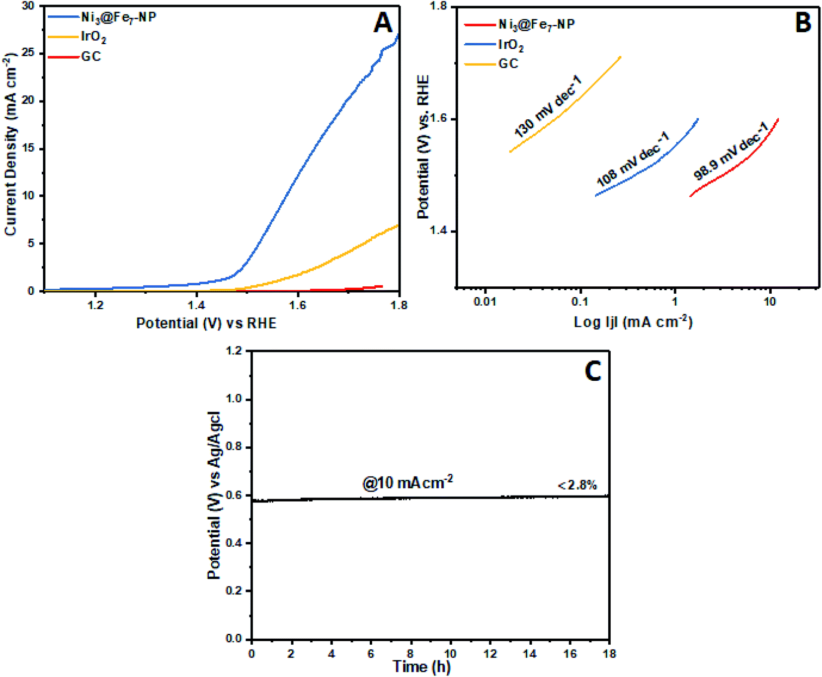 | ||
| Fig. 6 OER polarization curves (no iR-corrected) of Ni@Fe-NP in a 0.1 M KOH, (A); oxygen evolution reaction LSV curves (B) Tafel slopes and (C) chronopotentiometric durability test at 10 mA cm−2. | ||
 | ||
| Fig. 7 Oxygen evolution reaction (A) LSV curves of amorphous Ni@Fe-NP electrocatalysts at different ratio synthesis with loading amount of 0.030 mg cm−2 and (B) LSV curves of Ni3@Fe7-NP electrocatalyst at different loading amount on glassy carbon electrode. | ||
Furthermore, ECSA (electrochemical active surface area) is universally recognized as important evidence that electrocatalysis is significantly connected to the interaction between the catalyst surface and reaction intermediates (adsorbates O–O formation). The electrocatalytic activity difference directly determined by the reactivity of the catalyst surface which should be revealed by ECSA. The electrochemical double layer capacitance calculated on the basis of electrochemically active surface area for each system.62,63 Cyclic voltammogram (CVs) ±50 mV across the open circuit potential (OCP) were scanned at 10, 20, 30, 40 and 50 mV s−1 between the potential of 0.86 V to 1.16 V vs. RHE, at each scan rate, cyclic voltammogram curve shows the perfect broad rectangular behavior.
The rectangular behavior ratifies that the double layer capacitance may be because of the enhanced high electrochemical active surface area of the electrocatalyst. As we noticed that during CV from low scan rate to higher scan rate the ia (anodic) and ic (cathodic) cyclic voltammogram areas (current density) have been linearly increased up to 0.0190 mA cm−2. The ia (anodic) was measured with the potential at 0.88 V vs. RHE from each broad rectangular cyclic voltammogram spectra. The ia anodic current densities for each scan is plotted against the scan rates and also calculated slope using linear fit as shown in Fig. 8. The slope exhibits the double layer capacitance of Ni3@Fe7-NP (11.0 mF cm−2), Ni7@Fe3-NP (3.1 mF cm−2) and Ni5@Fe5-NP (1.9 mF cm−2), respectively, the high value of double layer capacitance of electrocatalyst increases the interaction with electrolyte.
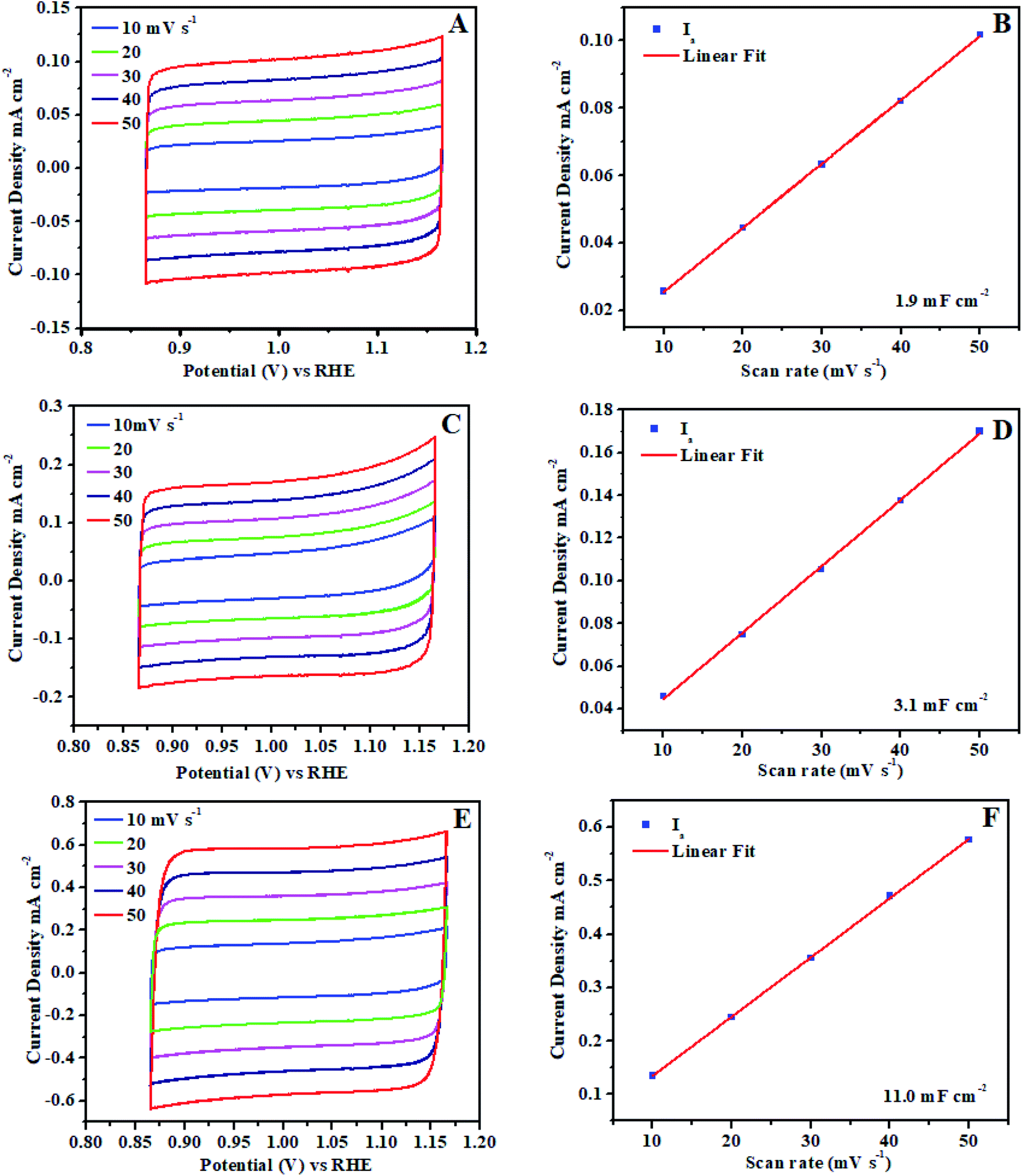 | ||
| Fig. 8 Electrochemical active surface area (ECSA) of amorphous Ni@Fe-NP electrocatalyst: (A and B) Ni5@Fe5-NP, (C and D) Ni7@Fe3-NP, (E and F) Ni3@Fe7-NP. | ||
The outstanding OER activity and durability of Ni@Fe-NP electrocatalyst on a glassy carbon electrode initiate us to develop very cheap and porous anode for commercial water splitter. The Ni@Fe-NP electrocatalyst (0.5 mg cm−2) was uniformly loaded on a porous nickel foam (0.5 cm−2) as a current collector (Ni@Fe-NP/Ni foam substrate) to increase the active surface area and reduce the stress by giving a pathway for oxygen bubble evolution in a harsh alkaline solution. A current density of 10 mA cm−2 was delivered by Ni@Fe-NP/Ni foam support electrocatalyst at 211 mV overpotential which is 170 mV lower than that of IrO2/Ni foam support (overpotential of 381 mV at 10 mA cm−2) as shown in Fig. 9A. The bare Ni foam requires a very high overpotential of 421 mV and also compared with the recently reported good OER activity nickel–iron based electrocatalyst (Table S1†). The Tafel slope of Ni@Fe-NP/Ni foam electrode was 84.2 mV dec−1 which was significantly small than that of IrO2/Ni foam (164 mV dec−1) and bare Ni foam (199 mV dec−1) (Fig. 9B). Therefore, the Ni@Fe-NP/Ni foam electrode has highly favorable kinetics to overcome the sluggish OER issue in alkaline solution.
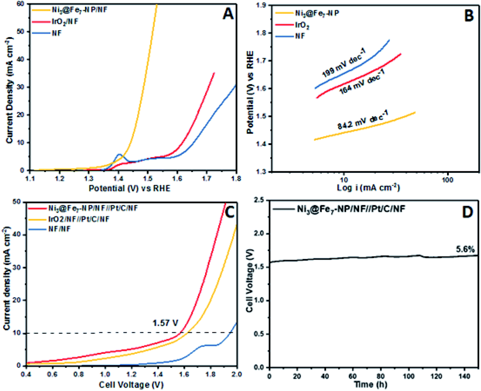 | ||
| Fig. 9 Electrochemical: (A) OER LSVs curves of Ni@Fe-NP/NF, IrO2/NF and bare Ni foam (scan rate: 10 mV s−1); (B) Tafel plot; (C) full cell LSVs (scan rate 10 mV s−1); (D) chronopotentiometry durability test at constant current density of 10 mA cm−2. | ||
The long-term durable test of Ni@Fe-NP/Ni foam electrode with fixed current density of 10 mA cm−2 over 130 h of continuous OER operation and catalyst morphology was displayed in Fig. S4.† The Ni@Fe-NP/Ni foam electrode exhibit exceptional electrode stability with an insignificant potential loss of 4.1% at 130 h for nonstop operating condition. During oxygen evolution reaction, gas bubbles liberation was continuously detected on the electrode surface whereas the previous reports shows that the RuO2 is more unstable than IrO2.64,65 The Ni@Fe-NP/Ni foam electrode exhibits superior stability compared with recently reported Ni–Fe based OER electrocatalysts. The remarkable OER results of Ni@Fe-NP electrocatalyst allowed us to assemble a close to real scale conventional water electrolyzer with 20% Pt/C/Ni foam cathode (Fig. S7†).
The LSV in Fig. 9C shows the cell voltage of water electrolyzers, the precious Pt/C as a cathode and nonprecious (Ni@Fe-NP) as an anode. The precious catalyst IrO2/Ni foam anode with 20% Pt/C/Ni foam cathode shows 1.62 V cell voltage at overall water splitting current density of 10 mA cm−2. However, the non-precious Ni@Fe-NP/Ni foam anode electrode electrolyzer only required 1.57 V to reach 10 mA cm−2 current density. The obtained voltage 50 mV is lower than that required by the voltage of precious metal anode of IrO2/Ni foam (Table S1†). The bare Ni foam water electrolyzer begins water splitting at 1.75 V. The long term durability water splitting test was investigated for the same two electrodes set up as shown in Fig. 9D. Initially, Ni@Fe-NP electrocatalyst requires 1.57 V (without iR-correction) to reach 10 mA cm−2 and then it was gradually increased without major increment up to 1.67 V at 150 h continues the long-lasting test. To this end, after 150 h durability test, it required only 1.67 V afford 10 mA cm−2.
The largest natural renewable resource is solar energy which is the ideal source to increase hydrogen production.66 Accordingly, the solar renewable energy used alkaline water splitting into solar to hydrogen fuel production has shown in Fig. S9.† It is new pathway of renewable energy production. Therefore, the solar panel was coupled with usual electrolyzer due to high OCV and current density of GaAs thin film solar cell which can produce a maximum voltage of 6.1 V depends on the distance between solar panel and lamp (Fig. S5†). A common electrolyzer produces hydrogen fuel continuously by water splitting (Movie S2†).
Finally, the charge transfers resistance (Rct) is measured for all different ratio electrocatalysts using electrochemical impedance spectroscopy technique to understand the influence of amorphous nature rippled nanostructure on the enhancement of the activity (Fig. S6†). This is due to its short charge diffusion, ESCA and enhanced conductivity of the catalyst. The results are in line with OER results.38–44 Overall, our results (electrochemical active surface area (ECSA), XPS and interfacial charge transfer resistance) show that there is a strong oxy/hydroxide in situ formation leading to the best OER catalytic activity (0.1 M KOH) and stability.
4. Conclusion
In summary, oxygen vacancy-rich materials possess high amount of defects and edges with low coordinated metals. Oxygen vacancies in catalyst structures increase the number of active sites and the electrical conductivity, offering 10 mA cm−2 at low overpotential (211 mV). The low Tafel slope of Ni3@Fe7-NP signified the superior reaction kinetics in the OER. The calculated TOF of different ratio Ni-doped FeOH-NP was 0.072 s−1, 0.0053 s−1, 0.0046 s−1 for Ni3@Fe7-NP, Ni5@Fe5-NP, Ni7@Fe3-NP, respectively at OER potential 1.60 V (vs. RHE). As expected, the as-prepared catalysts Ni3@Fe7-NP, Ni5@Fe5-NP, Ni7@Fe3-NP show better OER activity. The long-term durable test of Ni@Fe-NP/Ni foam electrode at fixed current density of 10 mA cm−2 over 150 h of continuous OER operation exhibit exceptional electrode stability with an insignificant potential loss of 5.6% at 150 h for nonstop operating condition. Each mixed-metal composition in this first generation of OER catalysts produced by low cost, facile and scalable solvothermal method exhibits catalytic parameters that approach those of the most active catalysts in the literature. Given the broad applicability of current method and stoichiometric control of metal compositions, we confirm that solvothermal technique opens a new parameter space for optimization of heterogeneous electrocatalysts.Conflicts of interest
There are no conflicts to declare.References
- T. R. Cook, D. K. Dogutan, S. Y. Reece, Y. Surendranath, T. S. Teetsand and D. G. Nocera, Chem. Rev., 2010, 110, 6474–6502 CrossRef CAS PubMed.
- M. G. Walter, E. L. Warren, J. R. McKone, S. W. Boettcher, Q. Mi, E. A. Santori and N. S. Lewis, Chem. Rev., 2010, 110, 6446–6473 CrossRef CAS PubMed.
- J. Suntivich, K. J. May, H. A. Gasteiger, J. B. Goodenough and Y. S. Horn, Science, 2011, 334, 1383–1385 CrossRef CAS PubMed.
- M. W. Kananand and D. G. Nocera, Science, 2008, 321, 1072–1075 CrossRef PubMed.
- D. Galizzioli, F. Tantardiniand and S. Trasatti, J. Appl. Electrochem., 1974, 4, 57–67 CrossRef CAS.
- J. Horkans and M. W. Shafer, J. Electrochem. Soc., 1977, 124, 1202–1207 CrossRef CAS.
- J. O. Bockris and T. Otagawa, J. Phys. Chem., 1983, 87, 2960–2971 CrossRef CAS.
- M. Hamdani, R. N. Singh and P. Chartier, Int. J. Electrochem. Sci., 2010, 5, 556–577 CAS.
- E. Tsuji, A. Imanishi, K. I. Fukui and Y. Nakato, Electrochim. Acta, 2011, 56, 2009–2016 CrossRef CAS.
- D. K. Zhongand and D. R. Gamelin, J. Am. Chem. Soc., 2010, 132, 4202–4207 CrossRef PubMed.
- D. K. Zhong, S. Choi and D. R. Gamelin, J. Am. Chem. Soc., 2011, 133, 18370–18377 CrossRef CAS PubMed.
- B. Klahr, S. Gimenez, F. Fabregat-Santiago, J. Bisquert and T. W. Hamann, J. Am. Chem. Soc., 2012, 134, 16693–16700 CrossRef CAS PubMed.
- A. J. Esswein, Y. Surendranath, S. Y. Reeceand and D. G. Nocera, Energy Environ. Sci., 2011, 4, 499–504 RSC.
- M. Dincă, Y. Surendranath and D. G. Nocera, Proc. Natl. Acad. Sci. U. S. A., 2010, 107, 10337 CrossRef PubMed.
- J. D. Blakemore, N. D. Schley, G. W. Olack, C. D. Incarvito, G. W. Brudvig and R. H. Crabtree, Chem. Sci., 2011, 2, 94–98 RSC.
- A. Bergmann, I. Zaharieva, H. Dau and P. Strasser, Energy Environ. Sci., 2013, 6, 2745–2755 RSC.
- A. T. Marshall and R. G. Haverkamp, Electrochim. Acta, 2010, 55, 1978–1984 CrossRef CAS.
- D. A. Corrigan, R. S. Conell, C. A. Fierro and D. A. Scherson, J. Phys. Chem., 1987, 91, 5009–5011 CrossRef CAS.
- A. Yamaguchi, R. Inuzuka, T. Takashima, T. Hayashi, K. Hashimoto and R. Nakamura, Nat. Commun., 2014, 5, 4256–4262 CrossRef CAS PubMed.
- J. W. D. Ng, M. G. Melchor, M. Bajdich, P. Chakthranont, C. Kirk, A. Vojvodic and T. F. Jaramillo, Nat. Energy, 2016, 1, 16053–16061 CrossRef CAS.
- Y. Gorlinand and T. F. Jaramillo, J. Am. Chem. Soc., 2010, 132, 13612–13614 CrossRef PubMed.
- X. Long, J. Li, S. Xiao, K. Yan, Z. Wang, H. Chen and S. Yang, Angew. Chem., 2014, 126, 7584–7588 CrossRef PubMed.
- F. Song and X. Hu, Nat. Commun., 2014, 5, 4477–4486 CrossRef CAS PubMed.
- L. Trotochaud, S. L. Young, J. K. Ranney and S. W. Boettcher, J. Am. Chem. Soc., 2014, 136, 6744–6753 CrossRef CAS PubMed.
- D. Friebel, M. W. Louie, M. Bajdich, K. E. Sanwald, Y. Cai, A. M. Wise, M. J. Cheng, D. Sokaras, T. C. Weng, R. AlonsoMori, R. C. Davis, J. R. Bargar, J. K. Norskov, A. Nilsson and A. T. Bell, J. Am. Chem. Soc., 2015, 137, 1305–1313 CrossRef CAS PubMed.
- H. Bode, K. Dehmelt and J. Witte, Electrochim. Acta, 1966, 11, 1079–1087 CrossRef CAS.
- A. M. Smith, L. Trotochaud, M. S. Burke and S. W. Boettcher, Chem. Commun., 2015, 51, 5261–5263 RSC.
- M. K. Bates, Q. Jia, H. Doan, W. Liang and S. Mukerjee, ACS Catal., 2016, 6, 155–161 CrossRef CAS.
- M. Görlin, P. Chernev, J. F. De Araujo, T. Reier, S. Dresp, B. Paul, R. Krähnert, H. Dau and P. Strasser, J. Am. Chem. Soc., 2016, 138, 5603–5614 CrossRef PubMed.
- J. Y. C. Chen, L. Dang, H. Liang, W. Bi, J. B. Gerken, S. Jin, E. E. Alp and S. S. Stahl, J. Am. Chem. Soc., 2015, 137, 15090–15093 CrossRef CAS PubMed.
- M. Balasubramanian, C. A. Melendres and S. Mini, J. Phys. Chem. B, 2000, 104, 4300–4306 CrossRef CAS.
- A. Grimaud, K. J. May, C. E. Carlton, Y.-L. Lee, M. Risch, W. T. Hong, J. Zhou and Y. Shao-Horn, Nat. Commun., 2013, 4, 2439–2446 CrossRef PubMed.
- Y. Q. Gao, X. Y. Liu and G. W. Yang, Nanoscale, 2016, 8, 5015–5023 RSC.
- L. Trotochaud, S. L. Young, J. K. Ranney and S. W. Boettcher, J. Am. Chem. Soc., 2014, 136, 6744–6753 CrossRef CAS PubMed.
- (a) L. Trotochaud, J. K. Ranney, K. N. Williams and S. W. Boettcher, J. Am. Chem. Soc., 2012, 134, 17253–17261 CrossRef CAS PubMed; (b) Y. H. Chiu, T. H. Lai, M. Y. Kuo, P. Y. Hsieh and Y. J. Hsu, APL Mater., 2019, 7, 080901–080912 CrossRef.
- (a) T. Shinagawa, M. T. K. Ng and K. Takanabe, Angew. Chem., Int. Ed., 2017, 56, 5061–5065 CrossRef CAS PubMed; (b) P. Y. Hsieh, J. Y. Wu, T. F. M. Chang, C. Y. Chen, M. Sone and Y. J. Hsu, Arabian J. Chem., 2020 DOI:10.1016/j.arabjc.2020.05.025.
- S. Klaus, M. W. Louie, L. Trotochaud and A. T. Bell, J. Phys. Chem. C, 2015, 119, 18303–18316 CrossRef CAS.
- N. Li, D. Kwabena Bediako, R. G. Hadt, D. Hayes, T. J. Kempa, F. v. Cube, D. C. Bell, L. X. Chen and D. G. Nocera, Proc. Natl. Acad. Sci. U. S. A., 2017, 114, 1486–1491 CrossRef CAS PubMed.
- Y. Gao, H. Li and G. Yang, Cryst. Growth Des., 2015, 15, 4475–4483 CrossRef CAS.
- L. Kuai, J. Geng, C. Chen, E. Kan, Y. Liu, Q. Wang and B. Geng, Angew. Chem., Int. Ed., 2014, 53, 7547–7551 CrossRef CAS PubMed.
- C. Xiao, Y. Li, X. Lu and C. Zhao, Adv. Funct. Mater., 2016, 26, 3515–3523 CrossRef CAS.
- X. Lu and C. Zhao, Nat. Commun., 2015, 6, 6616–6623 CrossRef CAS PubMed.
- R. D. Smith, M. S. Prevot, R. D. Fagan, S. Trudel and C. P. Berlinguette, J. Am. Chem. Soc., 2013, 135, 11580–11586 CrossRef CAS PubMed.
- Y. Q. Gao, X. Y. Liu and G. W. Yang, Nanoscale, 2016, 8, 5015–5023 RSC.
- (a) Y. Gao, H. Li and G. Yang, Cryst. Growth Des., 2015, 15, 4475–4483 CrossRef CAS; (b) Y. H. Hiu, K. D. Chang and Y. J. Hsu, J. Mater. Chem. A, 2018, 6, 4286–4296 RSC.
- (a) Y. Q. Gao, X. Y. Liu and G. W. Yang, Nanoscale, 2016, 8, 5015–5023 RSC; (b) Y. H. Chiu, T. H. Lai, C. Y. Chen, P. Y. Hsieh, K. Ozasa, M. Niinomi, K. Okada, T. F. M. Chang, N. Matsushita, M. Sone and Y. J. Hsu, ACS Appl. Mater. Interfaces, 2018, 10, 22997–23008 CrossRef CAS PubMed.
- H. B. Li, M. H. Yu, F. X. Wang, P. Liu, Y. Liang, J. Xiao, C. X. Wang, Y. X. Tong and G. W. Yang, Nat. Commun., 2013, 4, 1894–1901 CrossRef CAS PubMed.
- Y. Gao, H. Li and G. Yang, Cryst. Growth Des., 2015, 15, 4475–4483 CrossRef CAS.
- J. Y. Z. Fan, W. Sun, G. Ning, T. Wei, Q. Zhang, R. Zhang, L. Zhi and F. Wei, Adv. Funct. Mater., 2012, 22, 2632–2641 CrossRef.
- J. W Lee, T. Ahn, D. Soundararajan, J. M. Koc and J. Kim, Chem. Commun., 2011, 47, 6305–6307 RSC.
- J. Grossnickle, G. Vlases, A. Hoffman, P. Melnik, R. Milroy, A. Tankut and K. Velas, Phys. Plasmas, 2010, 17, 032506–032516 CrossRef.
- L. Zeng, W. Ren, J. Zheng, A. Wu and P. Cui, Appl. Surf. Sci., 2012, 258, 2570–2575 CrossRef CAS.
- J. Baltrusaitis, D. M. Cwiertny and V. H. Grassian, Phys. Chem. Chem. Phys., 2007, 9, 5542–5554 RSC.
- D. Xiong, W. Li and L. Liu, Chem.–Asian J., 2017, 12, 543–551 CrossRef CAS PubMed.
- Y. Gorlin and T. F. Jaramillo, J. Am. Chem. Soc., 2010, 132, 13612–13614 CrossRef CAS PubMed.
- M. E. G. Lyons and M. P. Brandon, Int. J. Electrochem. Sci., 2008, 3, 1386 CAS.
- R. D. L. Smith, M. S. Prevot, R. D. Fagan, S. Trudel and C. P. Berlinguette, J. Am. Chem. Soc., 2013, 135, 11580–11586 CrossRef CAS PubMed.
- F. Song and X. Hu, J. Am. Chem. Soc., 2014, 136, 16481–16484 CrossRef CAS PubMed.
- N. Jianwei, Y. Huajie, Y. Tingting, Z. Lirong, Z. Jing, W. Pengxi, J. Zhao, T. Yu, L. Juzhe, T. Zhiyong and G. Lin, Adv. Energy Mater., 2015, 5, 1401880–1401887 CrossRef.
- Y. Qiu, L. Xin and W. Z. Li, Langmuir, 2014, 30, 7893–7901 CrossRef CAS PubMed.
- I. J. Godwin and M. E. G. Lyons, Electrochem. Commun., 2013, 32, 39–42 CrossRef CAS.
- F. Song and X. Hu, J. Am. Chem. Soc., 2014, 136, 16481–16484 CrossRef CAS PubMed.
- D. Zhang, L. Meng, J. Shi, N. Wang, S. Liu and C. Li, Electrochim. Acta, 2015, 169, 402–408 CrossRef CAS.
- S. Cherevko, S. Geiger, O. Kasian, N. Kulyk, J. P. Grote, A. Savan, B. R. Shrestha, S. Merzlikin, B. Breitbach, A. Ludwig and K. J. J. Mayrhofer, Catal. Today, 2016, 262, 170–180 CrossRef CAS.
- L. C. Seitz, C. F. Dickens, K. Nishio, Y. Hikita, J. Montoya, A. Doyle, C. Kirk, A. Vojvodic, H. Y. Hwang, J. K. Norskov and T. F. Jaramillo, Science, 2016, 353, 1011–1014 CrossRef CAS PubMed.
- J. Li, Y. C. Wang, T. Zhou, H. Zhang, X. Sun, J. Tang, L. Zhang, A. M. Al-Enizi, Z. Yang and G. Zheng, J. Am. Chem. Soc., 2015, 137, 14305–14312 CrossRef CAS PubMed.
Footnote |
| † Electronic supplementary information (ESI) available. See DOI: 10.1039/d0ra04828c |
| This journal is © The Royal Society of Chemistry 2020 |