 Open Access Article
Construction of a silicate-based epitaxial transition film on a zirconia ceramic surface to improve the bonding quality of zirconia restorations
Xiuju Liu a,
Han Wanga,
Shiyang Yua,
Qi Zhaoa,
Zuosen Shib,
Zhanchen Cui
 *b and
Song Zhu*a
aDepartment of Prosthetic Dentistry, School and Hospital of Stomatology, Jilin University, Changchun 130021, P. R. China. E-mail: zhusong1965@163.com
bState Key Lab of Supramolecular Structure and Materials, College of Chemistry, Jilin University, Changchun 130021, P. R. China
First published on 4th September 2020
Abstract
The effect of a silicate-based epitaxial transition film on zirconia produced by a silicate solution during zirconia–resin bonding was investigated. The airborne-particle abraded zirconia was placed in different concentrations of silicate solutions and heated at 50 °C. The silicate transition film was characterized by scanning electron microscopy (SEM), atomic force microscopy (AFM), energy-dispersive X-ray spectroscopy (EDX), contact angle measurement and profilometry. The silicate-based epitaxial transition film was successfully constructed on the surface of zirconia, and the surface morphology and composition of zirconia changed. After coupling with KH570 hydrolysate, the shear bond strength (SBS) of zirconia–resin after either 24 h water storage or 5000 thermal cycles can be significantly improved by a silicate-based epitaxial transition film on the surface of zirconia, and all the samples had no cytotoxicity. This may provide a new strategy for improving the bonding quality of zirconia restorations.
1 Introduction
Because of the good biocompatibility, excellent aesthetics, high flexural strength, and good toughness produced by the phase transformation toughening mechanism, yttria-stabilized tetragonal zirconia polycrystalline (Y-TZP) materials are receiving attention as dental materials. However, it is difficult to obtain high bond strength, which affects the clinical prosthetic effect. How to improve the bond strength of zirconia ceramics is one of the challenges in the development of dental materials. There are two main factors that make it difficult for zirconia ceramics to achieve ideal bonding. ① After densification and sintering, zirconia ceramics do not contain a glass phase (without a silicon component) and have a strong chemical stability. Silane coupling agents do not typically form chemical bonds with zirconia ceramics.1 ② The phase structure of zirconia is uniform and dense, which is not conducive to the formation of micromechanical retention. In particular, when the preparation lacks a retention form (such as the bonding bridge of anterior teeth) or the retention form is limited and has to bear a large occlusal force (such as the fixed bridge of posterior teeth), the retention force of the prosthesis mainly depends on the adhesive force, and there are elevated requirements for the bond strength.2 Therefore, imparting silicon-containing components to the surface of zirconia ceramics is the key to improving the quality of the bonding.3Many scholars have tried to use surface treatment methods to prepare silicon-containing coatings on zirconia ceramic surfaces, such as a tribochemical silicon coating,4,5 plasma deposition,6,7 thermochemical etching,8,9 a silicon-based ceramic coating10–13 and sol–gel methods.14–16 Some of these treatment methods need to be further studied to improve the long-term stability of the zirconia ceramic bonding. Some of them have the disadvantages of expensive equipment, complicated operations and need to be operated by professional technicians, which are difficult to use in clinical applications. It is noteworthy that if the surface silicon coating treatment (including the sol–gel method) is followed by densification sintering, the zirconia ceramic experiences larger volume shrinkage, and the surface area also decreases. The silicon coating is not uniform and complete,14,17,18 and even the relative silicon content is significantly reduced after densification sintering.18 It is an urgent problem to prepare silicon-containing transition films on the surface of zirconia ceramics by a feasible method to obtain a high and durable bond strength.
Water-soluble silicates are a complex colloidal solution that has the dual characteristics of a solution and a colloid and is composed of an alkali metal oxide and silicon dioxide. According to the type of alkali metal oxide, the water-soluble silicates are mainly comprised of a sodium silicate or potassium silicate. Since it became an industrial product in the 19th century, silicates have been widely used in many fields due to the widespread availability of the raw materials, the simple processing, low price, excellent water resistance and compatibility with substrates. Due to their readily available resources and environmental friendliness, water-soluble silicates are used as an adhesive in the paint industry and are widely used as inorganic coatings (including exterior inorganic building coatings, functional inorganic building coatings and inorganic anticorrosive coatings).19,20
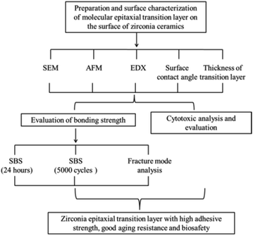
In light of the bond quality issues with zirconia ceramics, in this study, the molecular epitaxy method is used. As the nucleation site, zirconia induces the growth of silicate crystals. Finally, an epitaxially grown silicate transition film is prepared on the surface of zirconia ceramics after densification and sintering to form a stable chemical bond with zirconia. The transition film prepared by this method is uniform, and the surface of the zirconia ceramics is not damaged. In addition, the transition film readily combines with the silane coupling agent. Therefore, the zirconia, silane coupling agent and resin cement can be combined as a whole to truly improve the bond strength and aging resistance of the zirconia prosthesis. Fig. 1 shows the design and flow chart of this experiment.
2 Materials and methods
2.1 Preparation of the zirconia ceramic specimens
The zirconia blocks (8.0 mm × 8.0 mm × 3.0 mm and 4.0 mm × 4.0 mm × 3.0 mm) were prepared from zirconia (Lava; 3M ESPE) in a cutting machine (SYJ-160, Shenyang Kejing Co Ltd, Shenyang, P. R. China). The specimens were sintered according to the manufacturer's instructions. The zirconia blocks were polished with 600-, 800-, 1000- and 1500-grit silicon carbide abrasive papers for 10 s under running water, cleansed ultrasonically for 10 min in 70% ethanol and rinsed with 70% ethanol using an ultrasonic bath (Eurosonic Energy, Euronda Inc., Vicenza, Italy). They were then air-dried at room temperature for 30 min. The zirconia specimens were airborne-particle abraded with 50 μm aluminum oxide (Rocatec, 3M ESPE, St. Paul, MN, USA) perpendicular to the zirconia surface (0.25 MPa pressure, 10 mm distance, 10 s) and rinsed ultrasonically in 70% ethanol for 10 min. They were dried in air for 30 min.2.2 Preparation and surface characterization of the zirconia modified by silicate-based film
Different concentrations of silicate solution were prepared by using 90 wt% ethylene glycol ether and 10 wt% deionized water as a diluent (Table 1). According to the mass percentage of Si in silicate solution, the zirconia specimens prepared in Section 2.1 were divided into 6 groups: sandblasted control group, 1 wt% group, 2 wt% group, 3 wt% group, 4 wt% group and 5 wt% group. The specimens were immersed in different concentrations of silicate solution. After soaking for 5 min under ultrasonic vibration, the zirconia specimens were removed and allowed to stand at room temperature for 24 h. The specimens were heated at 50 °C for 10 h. After the samples cooled to room temperature, they were rinsed with deionized water to remove the unreacted solution and then dried in air. The silicate-based epitaxial transition film on the zirconia surface was characterized and the samples are named zirconia modified by silicate-based film.| Si concentration | 20% silicate | Diluent | 1% leveling agent | 10% glycol |
|---|---|---|---|---|
| 1 wt% | 0.5 g | 7.5 g | 1.0 g | 1.0 g |
| 2 wt% | 1.0 g | 7.0 g | 1.0 g | 1.0 g |
| 3 wt% | 1.5 g | 6.5 g | 1.0 g | 1.0 g |
| 4 wt% | 2.0 g | 6.0 g | 1.0g | 1.0 g |
| 5 wt% | 2.5 g | 5.5 g | 1.0 g | 1.0 g |
The zirconia modified by silicate-based film were analyzed by the Fourier Transform Infrared (FTIR) spectrometer (VERTEX 80V; Bruker, Germany). The surface morphologies of all samples were examined by scanning electron microscopy (SEM, S-4800, Hitachi, Japan). The elemental compositions of the samples were analyzed by energy-dispersive X-ray spectroscopy (EDX, QUANTAX 400, Luke AXS Co. Ltd, Germany). The presence of Si on the surface of the specimens was determined and confirmed the successful preparation of the silicate-based epitaxial transition film on the zirconia surface. Elemental mapping was employed to examine the element distribution in the films. The three-dimensional morphologies of the sample surfaces were characterized through atomic force microscopy (AFM, Veeco Digital Instruments, NY, USA). The surface roughness of each sample was also acquired. Five readings were taken randomly at different regions for each sample surface. Furthermore, the water contact angle was measured by contact angle measurement (DSA20, MK2 KR SS Edward Keller Co. Ltd, Germany) by the hanging-drop method using deionized water on the surface of the samples at different positions. The film thickness of the silicate-based epitaxial transition film on the surface of zirconia ceramics was measured by a probe profilometer (DEKTAK 150, Veeco Digital Instruments, NY, USA).
2.3 Hydrolysis and application of the silane coupling agent
The hydrolysate consisted of ethyl orthosilicate (6.0 g), anhydrous ethanol (30.0 g), glacial acetic acid (0.1 g) and deionized water (0.3 g) and was stirred by magnetic force for 1 h. γ-Methacryloxypropyltrimethoxysilane (KH570) (3.0 g) with C![[double bond, length as m-dash]](https://www.rsc.org/images/entities/char_e001.gif) C was added into the above mixed solution by dropping, and the solution was sufficiently hydrolyzed by magnetic stirring for 24 h to prepare the KH570 hydrolyzate. The zirconia specimens prepared in Section 2.2 were placed in the KH570 hydrolysate for 10 h, removed and dried in an oven at 50 °C for 3 h.
C was added into the above mixed solution by dropping, and the solution was sufficiently hydrolyzed by magnetic stirring for 24 h to prepare the KH570 hydrolyzate. The zirconia specimens prepared in Section 2.2 were placed in the KH570 hydrolysate for 10 h, removed and dried in an oven at 50 °C for 3 h.
2.4 Luting
Resin cement Multilink Speed (Ivoclar Vivadent AG, Liechtenstein) was activated according to the instructions provided by the manufacturer. A light-cured composite resin cylinder Filtek Z350 (3M ESPE, USA) (diameter 2.7 mm, height 4.0 mm) was placed onto the zirconia surface (prepared in 2.3). The excess cement was removed after light polymerization for 3–5 s using a light curing machine (SLC-VIIIA, Hangzhou Quartet Medical Devices Co Ltd, Hangzhou, China) with a light power density of 900 mW cm−2 monitored by a Cure Rite radiometer. The specimens were light polymerized from two opposite lateral directions of the block for 20 s each. The bonded specimens were stored in distilled water at 37 °C for 24 h. Then, each group was divided into two subgroups: the first subgroup (n = 9) was tested the bond strength; the second subgroup (n = 9) was subjected to thermal cycling (Proto-Tech, Micoforce, Portland, OR, USA) for 5000 cycles between 5.0 ± 0.5 °C and 55.0 ± 0.5 °C prior to bond strength testing. The dwelling time in each deionized water bath was 30 s.2.5 Shear bond strength
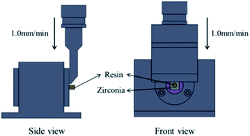
The shear bond strength (SBS) was measured with a universal testing machine (AG-Xplus10KN; Shimadzu, Kyoto, Japan). A constant load of 1 kN was applied with a cross-head speed of 1.0 mm min−1 until failure occurred (as showed in Fig. 2). The SBS was calculated according to the following formula: P = F/S, where P is the shear bond strength (MPa), F is the maximum shear force (N), and S is the bonding area (mm2).After shear bond strength testing, the failure mode was determined with a stereoscopic microscope (SZX16, OLYMPUS Co Ltd, Tokyo, Japan) under 20× magnification. They were assigned as “adhesive” at the resin cement–zirconia interface or resin cement-composite resin cylinder interface, “cohesive” within the resin cement, composite resin cylinder or zirconia ceramic, or “mixed”, which was a combination of both adhesive and cohesive failure modes.
2.6 Cytotoxicity test
The zirconia modified by silicate-based film specimens prepared in Section 2 were put into culture dishes, transferred to a clean bench (BLB-1300, Suzhou Sujing Baishen Technology Co. Ltd, China), subjected to UV irradiation for 2 h and then turned over after 1 h. A high glucose culture medium (Nanjing Jiancheng Biological Co., China) was added to the culture dish containing the sterile specimens. The resulting culture medium was then placed in a CO2 incubator (MCO-20IL, Sanyo, Japan) at 37 °C for 72 h to prepare the extraction solution.Mouse fibroblasts (L929, Cells Resource Center, Shanghai Institutes of Biological Science, China) were resuscitated in high glucose cell culture medium containing 10% fetal bovine serum and incubated at 37 °C in 5% CO2 and 95% relative humidity. L929 cells in logarithmic growth phase were digested with 0.25% trypsin, centrifuged and discarded the supernatant. The cell suspension was prepared by adding appropriate amount of high glucose medium. The cell suspension with a concentration of 2 × 10⁴/mL was added to 96-well plates (Costar, USA) according to 2000 cells per well. The following nine groups were then used for subsequent experiments: blank control (pure high glucose medium), negative control (PE), positive control (phenol), sandblasted control group, 1 wt% group, 2 wt% group, 3 wt% group, 4 wt% group and 5 wt% group. The marked 96-well plates were placed in a cell incubator (5% CO2, 95% humidity). After incubation for 24 h at 37 °C, the supernatant was removed, and 100 μL extraction solution was added into each hole. After 24 h, 48 h and 72 h of culture, the cell culture was terminated. Mitochondrial dehydrogenase in living cells enabled the MTT to become insoluble formazan particles that can dissolve in dimethyl sulfoxide (DMSO). Then, 20 μL of MTT solution (5 mg mL−1) was added to each well and the incubated for 4 h. Next, 150 μL of DMSO was added to each well, and the 96-well plate was shaken at a low speed for 10 min to fully dissolve the crystal formazan particles. The absorbance (A) was measured at 490 nm with a microplate reader (BL340, Biotech, USA). The relative growth rate (RGR) of the cells was calculated using the following formula: RGR = experimental group A value/blank control group A value × 100%.
Furthermore, the toxicity levels of the samples and the safety standards21 were determined according to Table 2.
| RGR | Toxicity levels | Safety standards |
|---|---|---|
| ≥100 | 0 | Safe |
| 75–99 | I | Safe |
| 50–74 | II | Insecurity |
| 25–49 | III | Insecurity |
| 1–24 | IV | Insecurity |
| <1 | V | Insecurity |
2.7 Statistical analysis
Data were described as mean ± SD. After accorded with normal probability distribution and homogeneity of variance using Kolmogorov–Smirnov test and Levene's test, the data were analyzed by a two-way analysis of variance (ANOVA) (p = 0.05) with the shear bond strength as the dependent valuable and surface treatments and storage conditions as the independent valuables (SPSS 22.0, SPSS Inc., Chicago, IL, USA). A post hoc Tukey's test (p = 0.05) was used to compare the means of the shear bond strength results.3 Results and discussion
3.1 FTIR spectra of samples
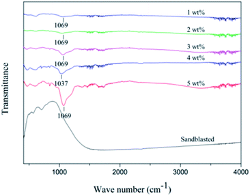
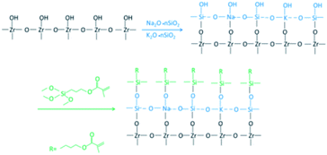
The FTIR spectra of the different samples are shown Fig. 3. The obvious absorption peaks at 1069 cm−1 can be seen in 1 wt%, 2 wt%, 3 wt% and 5 wt% FTIR spectra, and 1037 cm−1 in 4 wt% FTIR spectra. The bands at 1069 cm−1 and 1037 cm−1 corresponded to Si–O–Si and Si–O.22 With the increase of silicate concentration, the absorption peak area increases, which means that the chemical bond increases. However, there is no Si–O absorption peak in the FTIR spectra of sandblasted samples. Therefore, Si–O bond was successfully grafted on the surface of zirconia. The formation of chemical bond on the surface of zirconia was proved by the FTIR spectra.Fig. 4 is the reaction scheme of this study. Proper heat treated can improve the strength and bonding strength of the transition film, promote the condensation reaction of silicon hydroxyl groups in the transition film structure to form silicon oxygen bonds, and strengthen the Si–O–Si network. In this study, 50 °C was used to promote the reaction and improve the adhesion of the transition layer. The FTIR results show that Si–O is formed, which proves that there is chemical bond between zirconia and epitaxial transition layer. More silicon was introduced into the surface of zirconia to form Si–O–Si chemical bond between silane coupling agent and zirconia, which made up for the congenital defect of no glass phase on the surface of zirconia.
3.2 SEM images of the zirconia surfaces
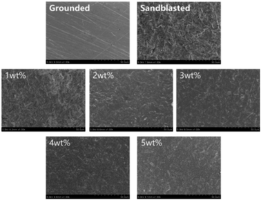
Fig. 5 shows the SEM images of the zirconia surfaces. After polishing, the surface of the zirconia ceramics was relatively smooth and flat, but scratches were observed. After airborne-particle abrasion, the surface of zirconia had ridges or grains, and the roughness appeared to increase significantly. For the silicate transition film group, the zirconia surface was covered with a uniform silicate transition film, and the transition film became increasingly compact as the solution concentration increased.Sandblasting can increase the surface roughness of zirconia and form a good micromechanical chimerism with bonding materials. The transition film was formed on the surface of sandblasted zirconia and can form a stable combination with its substrate after heated. In this experiment, sandblasting increases the contact area between zirconia and silicate, and promotes the better deposition and bonding of silicate particles on the surface of zirconia, which is conducive to the formation of silicon epitaxial transition layer. The SEM shows that the surface of epitaxial transition layers prepared by four silicate solutions is relatively smooth, and there is no obvious crack and defect, which indicates that the high quality silicon epitaxial transition layer can be prepared by this method.
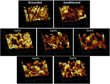
3.3 Three-dimensional morphology and surface roughness measurements
Fig. 6 and Table 3 display the three-dimensional morphology and surface roughness that were analyzed separately with AFM. The Ra describes the average roughness value of a plane. The larger the Ra is, the rougher the surface is. The three-dimensional surface morphology and surface roughness results show that the surface of the polished specimen was smooth and flat, without obvious groove or ridge structures, and the roughness was low. The surface roughness of the sandblasted specimen obviously increased, ridges or valleys were present, but there was no transition film. A uniform transition film can be seen on the surface of the silicate-based transition film specimen. With increasing solution concentration, the density of the transition film increased, and the surface roughness first decreased and then increased.![[x with combining macron]](https://www.rsc.org/images/entities/i_char_0078_0304.gif) ± s, n = 5)a
± s, n = 5)a
| Groups | Surface roughness (nm) | |
|---|---|---|
| Ra | Rq | |
| a Within the same column, the different superscripted letters indicate significant differences, P < 0.05. | ||
| Grounded | 32.47 ± 5.75a | 41.60 ± 4.20a |
| Sandblasted | 426.00 ± 6.56b | 510.00 ± 6.00b |
| 1 wt% | 211.67 ± 3.06c | 240.67 ± 8.50c |
| 2 wt% | 169.67 ± 3.51d | 205.33 ± 7.51d |
| 3 wt% | 120.33 ± 2.52e | 160.00 ± 4.58e |
| 4 wt% | 214.67 ± 7.09c | 296.33 ± 7.02f |
| 5 wt% | 269.33 ± 7.02f | 331.00 ± 6.93g |
| P | <0.001 | <0.001 |
The roughness of the 3 wt% group was the lowest (120.33 nm) and that of 5 wt% group was the highest herein (269.33 nm). This is because the particles impacted the surface of the zirconia during sandblasted, forming an uneven structure and increasing the surface roughness of the material. However, after the silicate solution treatment, the silicate was deposited on the rough surface of the zirconia by the hydroxyl groups, reducing the degree of the concave and convex features, thus reducing the surface roughness (1–3 wt% groups). As the concentration of the silicate increased, additional ions in the silicate deposited on the surface of the zirconia, forming a uniformly distributed granular structure and gradually forming a rugged structure, thereby increasing the surface roughness (4–5 wt% groups).
3.4 Surface element measurements
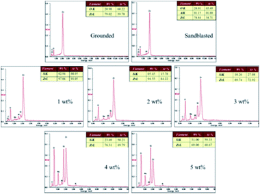
The EDX results (Fig. 7) show the elemental composition of the zirconia surfaces after various surface treatments. The polished specimen only contains Zr, O and C, and the sandblasted specimen contains Zr, O, C and Al. Si appeared on the surface of the silicate-based transition film specimen, and the Si content increased with increasing solution concentration. This indicates that Si was successfully incorporated into the surface of the zirconia ceramic.A chemical bond is formed between the zirconia surface and the resin matrix as a result of the application of a silane coupling agent. The hydroxyl in the silicate solution reacts with the hydroxyl groups on the surface of the zirconia, thus forming a silicon-rich epitaxial film. The main component of the silicate film is colloidal silica, and there are many theories about the film formation mechanism. It is now generally believed that the film that results is composed of colloidal silica with Si–O–Si as the main skeleton, which forms a network structure that contains dispersed metal ions. There are many Si–OH bonds in a silicate solution. When the temperature is gradually increased from room temperature, the water molecules rearrange and catalyze the condensation between adjacent silanol groups. The Si–O–Si bond network coating is formed by dehydration and association of Si–OH bonds.23,24 This is a three-dimensional cured system with excellent water resistance ability. The reaction formula of the film-forming mechanism is as follows:
When a silane coupling agent is applied on the surface of zirconia coated with a silicate-based epitaxial transition film, Si–O–Si links are formed from the Si–OH, which is formed after the acid-catalyzed hydrolysis of the silane and –OH on the surface of the zirconia. The other functional group in the silane coupling agent, C![[double bond, length as m-dash]](https://www.rsc.org/images/entities/char_e001.gif) C, reacts with the resin monomer.25 Thus, zirconia is chemically bonded to the resin by a silane coupling agent as an intermediate bridge. A chemical bond was therefore established between the zirconia and resin cement by the silane coupling agent.
C, reacts with the resin monomer.25 Thus, zirconia is chemically bonded to the resin by a silane coupling agent as an intermediate bridge. A chemical bond was therefore established between the zirconia and resin cement by the silane coupling agent.
3.5 Contact angle measurements
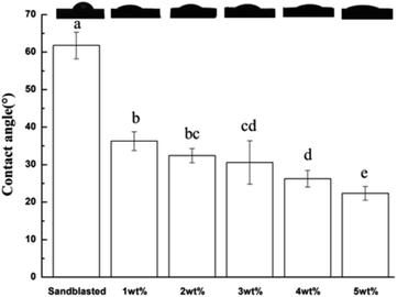
Fig. 8 shows the surface water contact angle of the specimens. Compared with that of the sand blasted control group, the contact angle of the water on the surface of the silicate-based transition film group decreased significantly (P < 0.01). With increasing silicate concentration, the water contact angle decreased. The water contact angle of 5 wt% specimens was the smallest herein (22.36 ± 1.83°). Thus, the hydrophilicity of the material improved and enhanced the flow and infiltration of the resin cement on the surface of the specimen, thereby increasing the bond specific surface area.3.6 Thickness measurements
Table 4 shows the thickness of the silicate-based transition film. With increasing silicate concentration, the thickness of the silicate-based transition film increased gradually. The transition film for the 1 wt% group was the thinnest (393.06 nm) and that of 5 wt% group was the thickest (1063.62 nm) herein and had a value of greater than 1 μm. The thickness of the transition film is an important factor affecting the bond strength. If the deposited film is thick, it may cause a lack of chemical bonding between the films formed during the deposition process, which leads to film fragmentation and peeling. Thick films have different coefficients of thermal expansion with zirconia ceramics. During the aging process of thermal cycling, stress concentration and cracking are easily formed at the interface between the film and zirconia, and the bond strength between resin cement and zirconia is reduced.7 In addition, if the film is too thick, it also affects the fit and edge suitability of the clinical restoration.26 In this experiment, the thickness of the transition film was less than 1 μm except for that in the 5 wt% group.![[x with combining macron]](https://www.rsc.org/images/entities/i_char_0078_0304.gif) ± s, n = 5)
± s, n = 5)
| Group | Thickness (nm) |
|---|---|
| 1 wt% | 393.06 ± 46.64 |
| 2 wt% | 802.60 ± 39.57 |
| 3 wt% | 908.13 ± 50.28 |
| 4 wt% | 978.33 ± 79.40 |
| 5 wt% | 1063.62 ± 39.80 |
3.7 Shear bond strength
Adhesion is one of the most critical factors in the zirconia repair process. The long-term and stable adhesion between the zirconia and resin is the prerequisite for ensuring marginal adaptation, preventing fracture of the prosthesis and improving the success rate.27 The bond strength between the zirconia and resin mainly depends on the micromechanical interlocking and chemical bonding. The resin monomer penetrates the irregular or rough zirconia surface. The resin monomer is converted into polymeric chains and microscopically locks onto the surface of the zirconia.28 Airborne-particle abrasion can promote micromechanical bonding by removing the poorly adhering films, roughening the zirconia surface, increasing the surface area for bonding, and improving wettability.29 In addition, studies have shown that sandblasted combined with a self-adhesive resin cement containing the functional monomer 10-methacryloyloxydecyl dihydrogen phosphate (10-MDP) is an ideal bonding strategy for current zirconia ceramic restoration.30,31 Therefore, in this experiment, we selected self-adhesive resin cement Multilink Speed containing 10-MDP as the adhesive.The SBS results are shown in Table 5. The concentration of the silicate solution and storage conditions had a significant effect on the SBS. The SBS of the silicate-based transition film group was significantly higher than that of the sandblasted control group. The SBS increased with increasing silicate solution concentration, and among the samples, the 5 wt% group had the highest strength (27.14 ± 2.87), which was significantly higher than that of the 1 wt% and 2 wt% groups (P < 0.05). After 5000 cycles, the SBS of the sand blasted group and the 1 wt% group decreased (P < 0.05), while the other silicate-based transition film groups did not (P > 0.05).
![[x with combining macron]](https://www.rsc.org/images/entities/i_char_0078_0304.gif) ± s, n = 9)a
± s, n = 9)a
| Groups | SBS (MPa) | ||
|---|---|---|---|
| 24 hours | 5000 cycles | P | |
| a Different lowercase letters represent statistically significant differences within the same line (p < 0.05; horizontal comparisons); different capital letters represent statistically significant differences within the same column (p < 0.05; vertical comparisons). | |||
| Sandblasted | 14.04 ± 1.36Aa | 8.94 ± 0.75Ab | <0.001 |
| 1 wt% | 23.59 ± 1.02Ba | 21.81 ± 0.87Bb | 0.008 |
| 2 wt% | 24.41 ± 1.60BCa | 22.42 ± 1.50Ba | 0.064 |
| 3 wt% | 26.37 ± 1.36CDa | 25.00 ± 1.93Ca | 0.076 |
| 4 wt% | 26.43 ± 1.56Da | 25.24 ± 0.92Ca | 0.111 |
| 5 wt% | 26.26 ± 1.33Da | 25.22 ± 1.38Ca | 0.090 |
| P | <0.05 | <0.05 | |
Under the two storage conditions, the mean shear bond strengths of the resin cement bonded to the zirconia in the transition film groups were significantly higher than those of the sandblasted group, and the shear bond strength increased with increasing silicate concentration. Upon comparing the roughness results, it can be seen that the shear bond strength did not improve as the micromechanical interlocking action increased. From the EDX analysis, Si was introduced into the surface of the zirconia after silicate solution treatment and accumulated with increasing silicate solution concentration. As the Si–O–Si between the zirconia and coupling agent grew in number, the chemical bonding increased, which shows the improvement in the shear bond strength between the resin and zirconia. Therefore, for this study, the micromechanical interlocking and chemical bonding was correlated with the bond strength, and the chemical bonding was the main factor that determined the shear bond strength.
The shear bond strengths measured for the sandblasted group and the 1 wt% group decreased after the artificial aging that occurred during thermal cycling. This might be due to the diffusion of water into the resin–zirconia interfacial film, which caused the degradation of the interfacial film.32 Therefore, the resin-to-zirconia bonding was weakened. In addition, the difference in the linear coefficient of thermal expansion of the resin cement and zirconia caused thermal stresses to develop at the resin–zirconia interface during the thermal cycling process, and the long-term hot water bath easily led to the hydrolysis of the resin monomer in the resin cement, thereby resulting in a reduced bond strength.33–35 However, in the 3 wt%, 4 wt% and 5 wt% groups, the bond strength did not decrease significantly after thermal cycling, and the aging resistance improved. This may be due to the further solidification of the silicate-based transition film during thermal cycling and the condensation reaction of the silicate at elevated temperatures to form a cured system with a three-dimensional structure of Si–O–Si with excellent water resistance. The Si–O–Si chemical bonding of increased and increased the resistance to water degradation or thermal stress at the bonding interface.23,24
3.8 Failure modes
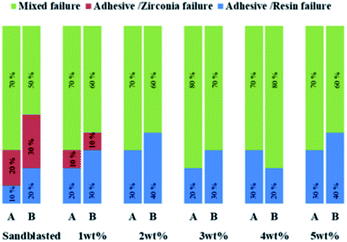
The analysis of the failure modes (Fig. 9) for debonded zirconia samples after the SBS test showed that the predominant mode of failure was mixed before and after thermal cycling. Analysis of the failure mode can help to explain the bond strength results. The SBS was determined to be related to two bond interfaces (the adhesive/zirconia interface and adhesive/composite resin interface), and the failure often occurred at the weaker interface between the two.36 In the present investigation, low bond strength values were usually associated with cohesive failures.37 Only the control group and 1 wt% group had adhesive/zirconia interface failure, which means that the adhesion between the zirconia and adhesive was weak. The predominant failure mode of the other four transition film groups comprised mixed failures before and after thermal cycling. The silicon increased the chemical bond strength between the zirconia and adhesive.3.9 Cytotoxicity
The biological safety of medical materials is the precondition for its clinical application. The cell absorbance values, RGR values and cytotoxicity grades are shown in Tables 6 and 7. As shown in Table 6, at the same time point, the A values of the negative control group, blank control group, and sandblasted group were basically similar, and they were not significantly different from those of the silicates-based transition film groups (P > 0.05). Moreover, no significant difference was observed among the silicate-based transition film groups (P > 0.05). There was a significant difference between the positive control group and the other groups (P < 0.01). It can be seen from Table 7 that at different time points, the negative control group, sandblasted group and each transition film group all showed an improved cell relative value-added rate, which was greater than 90%. The cytotoxicity level was 0 or 1, which indicated that the specimens had no cytotoxicity and can be considered biologically safe materials.![[x with combining macron]](https://www.rsc.org/images/entities/i_char_0078_0304.gif) ± s, n = 5)
± s, n = 5)
| 24 h | 48 h | 72 h | |
|---|---|---|---|
| Blank | 0.113 ± 0.011 | 0.272 ± 0.008 | 0.398 ± 0.006 |
| Negative | 0.113 ± 0.009 | 0.271 ± 0.012 | 0.402 ± 0.058 |
| Positive | 0.035 ± 0.001 | 0.023 ± 0.004 | 0.014 ± 0.002 |
| Sandblasted | 0.113 ± 0.004 | 0.271 ± 0.006 | 0.398 ± 0.004 |
| 1 wt% | 0.115 ± 0.002 | 0.278 ± 0.008 | 0.405 ± 0.005 |
| 2 wt% | 0.112 ± 0.001 | 0.270 ± 0.011 | 0.405 ± 0.012 |
| 3 wt% | 0.114 ± 0.009 | 0.271 ± 0.004 | 0.401 ± 0.007 |
| 4 wt% | 0.114 ± 0.012 | 0.274 ± 0.007 | 0.404 ± 0.004 |
| 5 wt% | 0.111 ± 0.012 | 0.276 ± 0.006 | 0.405 ± 0.012 |
| F | 0.098 | 0.443 | 0.466 |
| P | 0.000 | 0.000 | 0.000 |
| RGR (%) | Cytotoxicity grade | |||||
|---|---|---|---|---|---|---|
| 24 h | 48 h | 72 h | 2 h | 48 h | 72 h | |
| Positive | 31 | 8 | 4 | III | IV | IV |
| Negative | 100 | 100 | 101 | 0 | 0 | 0 |
| Sandblasted | 100 | 99 | 100 | 0 | I | 0 |
| 1 wt% | 102 | 102 | 102 | 0 | 0 | 0 |
| 2 wt% | 99 | 99 | 102 | I | I | 0 |
| 3 wt% | 101 | 100 | 101 | 0 | 0 | 0 |
| 4 wt% | 101 | 103 | 102 | 0 | 0 | 0 |
| 5 wt% | 98 | 97 | 102 | I | I | 0 |
The silicate solution used in this experiment mainly contained Na+, K+, Si+, and OH−. It had a low cytotoxicity because the median lethal dose (LD50) of silicate solution is 1280 mg kg−1 (rat, oral)38 and the silicate content of the samples in this experiment was far lower than the median lethal dose; thus, the silicate solution herein is not cytotoxic to the human body and meets the requirements of biomedical materials.
4 Conclusions
In summary, the silicate solution treatment successfully constructed a silicate-based epitaxial transition film on the surface of the zirconia, and the surface morphology and composition of the zirconia changed, which significantly improved the shear bond strength between the zirconia and composite resin. The bond strength and aging resistance of the 3 wt%, 4 wt% and 5 wt% groups improved, and there was no difference in the bonding effects. The film thicknesses in the 3 wt% and 4 wt% groups were less than 1 μm. Therefore, it is recommended that 3 wt% and 4 wt% are the optimum silicate solution concentrations for preparing a zirconia surface transition film that improves the bond strength. The toxicity grade of the samples prepared in this experiment was 0–1, which represents an acceptable level of biological safety.Conflicts of interest
There are no conflicts to declare.Acknowledgements
This research was financially supported by the National Natural Science Foundation of China (NSFC, Grant No. 81671033).Notes and references
- N. Nagaoka, K. Yoshihara, Y. Tamada, Y. Yoshida and B. V. Meerbeek, Dent. Mater. J., 2019, 38, 107–113 CrossRef CAS.
- M. Kern, Dent. Mater., 2015, 31, 8–14 CrossRef CAS.
- N. Mahmoodi, T. Hooshmand, S. Heidari and K. Khoshro, Lasers Med. Sci., 2015, 31, 205–211 CrossRef.
- A. A. Khan, A. A. A. Kheraif, S. Jamaluddin, M. Elsharawy and D. D. Divakar, J. Adhes. Dent., 2017, 19, 7–19 Search PubMed.
- A. M. O. D. a. Piva, R. L. A. Carvalho, A. L. Lima, M. A. Bottino, R. M. Melo and L. F. Valandro, J. Biomed. Mater. Res., Part B, 2019, 107, 104–111 CrossRef.
- J. R. C. Queiroz, D. A. Duarte, R. O. A. Souza, S. F. Fissmer, M. Massi and M. A. Bottino, Mater. Res., 2011, 14, 212–216 CrossRef.
- C. C. Druck, J. L. Pozzobon, G. L. Callegari, L. S. Dorneles and L. F. Valandro, J. Biomed. Mater. Res., Part B, 2015, 103, 143–150 CrossRef.
- C. Akay, M. Ç. Tanış and M. Şen, J. Prosthodontics, 2017, 26, 419–423 CrossRef.
- M. Ozcan, H. Nijhuis and L. F. Valandro, Dent. Mater. J., 2008, 27, 99–104 CrossRef CAS.
- R. Fushiki, F. Komine, M. B. Blatz, M. Koizuka, K. Taguchi and H. Matsumura, Clin. Oral Investig., 2012, 16, 1401–1411 CrossRef.
- M. N. Aboushelib, C. J. Kleverlaan and A. J. Feilzer, J. Prosthet. Dent., 2007, 98, 379–388 CrossRef CAS.
- C. Cura, M. Ozcan, G. Isik and A. Saracoglu, J. Adhes. Dent., 2012, 14, 75–82 CAS.
- N. C. Ramos, M. R. Kaizer, T. M. B. Campos, J. Kim, Y. Zhang and R. M. Melo, J. Dent. Res., 2019, 98, 423–429 CrossRef CAS.
- T. M. Campos, N. C. Ramos, J. P. Machado, M. A. Bottino, R. O. Souza and R. M. Melo, J. Dent., 2016, 48, 55–61 CrossRef CAS.
- C. Y. Lung, E. Kukk and J. P. Matinlinna, Dent. Mater. J., 2013, 32, 165–172 CrossRef CAS.
- B. Hossein, M. Azamsadat, K. Parisa, G. Rajabzadeh, S. Salehi and H. Bagheri, Int. J. Nanomed., 2016, 11, 3215–3223 CrossRef.
- M. Moezzizadeh, H. Nojedehian and H. V. Haghi, Dent. Mater. J., 2016, 36, 54–62 CrossRef.
- K. Ebeid, S. Wille, T. Salah, M. Wahsh, M. Zohdy and M. Kern, J. Mech. Behav. Biomed. Mater., 2018, 86, 84–88 CrossRef CAS.
- W. Chen, P. Dai, P. Yuan and J. Zhang, Constr. Build. Mater., 2016, 121, 445–452 CrossRef CAS.
- C. J. Yu, B. H. Ri, C. H. Kim, U. S. Hwang, K. C. Ri, C. J. Song and U. C. Kim, Mater. Chem. Phys., 2019, 227, 211–218 CrossRef CAS.
- XXII-NF XVII USP, United States Pharmacopeia Convention Inc, Rockville MD, 1990, pp. 644–645 Search PubMed.
- G. Socrates, Infrared and Raman characteristic group frequencies: table and charts, John Wiley & Sons, England, 2001, pp. 244–245 Search PubMed.
- A. Matsuda, Y. Matsuno, M. Tatsumisago and T. Minami, J. Sol-Gel Sci. Technol., 2001, 20, 129–134 CrossRef CAS.
- W. Cho, R. Saxena, O. Rodriguez, R. Achanta, J. L. Plawsky and W. N. Gill, J. Non-Cryst. Solids, 2004, 350, 336–344 CrossRef CAS.
- Y. K. Lung and J. P. Matinlinna, Silanes for adhesion promotion and surface modification, Nova Science Publisher Inc, New York, 2013, pp. 87–109 Search PubMed.
- S. Kitayama, T. Nikaido, M. Ikeda, S. Alireza, H. Miura and J. Tagami, Biomed. Mater. Eng., 2010, 20, 77–87 CAS.
- M. B. Blatz, A. Sadan and M. Kern, J. Prosthet. Dent., 2003, 89, 268–274 CrossRef CAS.
- C. Y. K. Lung, D. Liu and J. P. Matinlinna, Mater. Sci. Eng., C, 2015, 46, 103–110 CrossRef CAS.
- B. Yang, H. C. Lange-Jansen, M. Scharnberg, S. Wolfart, K. Ludwig, R. Adelung and M. Kern, Dent. Mater., 2008, 24, 508–513 CrossRef CAS.
- L. Mair and P. Padipatvuthikul, Dent. Mater., 2010, 26, e17–e23 CrossRef.
- E. Papia, C. Larsson, M. Du Toit and P. V. Von Steyern, J. Biomed. Mater. Res., Part B, 2014, 102, 395–413 CrossRef.
- M. Wolfart, F. Lehmann, S. Wolfart and M. Kern, Dent. Mater., 2007, 23, 45–50 CrossRef CAS.
- T. T. Heikkinen, L. V. J. Lassila, J. P. Matinlinna and P. K. Vallittu, J. Adhes. Sci. Technol., 2009, 23, 1043–1051 CrossRef CAS.
- N. Matsui, T. Takagaki, A. Sadr, M. Ikeda, S. Ichinose, T. Nikaido and J. Tagami, Dent. Mater. J., 2015, 34, 227–233 CrossRef CAS.
- D. Deng, X. Huang, C. Huang, T. Yang, X. Du, Y. Wang, X. Ouyang and D. Pei, Aust. Dent. J., 2013, 58, 148–155 CrossRef CAS.
- M. L. L. Alves, F. Campos, C. D. Bergoli, M. A. Bottino, M. Özcan and R. Souza, Oper. Dent., 2016, 41, 276–283 CrossRef.
- H. L. d. Castro, P. H. Corazza, A. Paes-Júnior Tde and A. D. Bona, Dent. Mater., 2012, 28, 1191–1197 CrossRef.
- A. R. Elmore, Int. J. Toxicol., 2005, 24, 103–117 Search PubMed.
| This journal is © The Royal Society of Chemistry 2020 |

