 Open Access Article
Free-standing lithiophilic Ag-nanoparticle-decorated 3D porous carbon nanotube films for enhanced lithium storage†
Fang Wu,
Heng Quan,
Jiang Han,
Xiaoli Peng,
Zongkai Yan,
Xiaokun Zhang and
Yong Xiang *
*
School of Materials and Energy, University of Electronic Science and Technology of China, Chengdu, 611731, China. E-mail: xyg@uestc.edu.cn
First published on 20th August 2020
Abstract
Lithium metal batteries are promising candidates for next generation high energy batteries. However, an undesirable dendrite growth hinders their practical applications. Herein, a three-dimensional (3D) porous carbon nanotube film decorated with Ag nanoparticles (CNT/Ag) has been synthesized via the thermal decomposition reaction of AgNO3 into Ag nanoparticles, and then is transformed into a 3D porous CNT/Ag/Li film via thermal infusion to obtain a high-performance free-standing lithium host. This as-formed 3D CNT/Ag/Li host can effectively restrain the dendrite growth by guiding Li deposition via the highly lithiophilic Ag nanoparticle seeds and lowering local current density of the highly conductive matrix. The as-prepared CNT/Ag/Li electrode exhibits long-term cycling stability over 200 cycles at a current density of 1 mA cm−2 with an areal capacity of 1.0 mA h cm−2. Moreover, the full cell paired with a sulfur/C cathode shows good cycling stability. Therefore, the 3D porous CNT/Ag/Li film formed via a facile three-step fabrication process can enlarge the cycle lifetime of a lithium metal anode.
Introduction
Lithium metal-based batteries (LMBs), such as Li–O2 and Li–S batteries, with ultrahigh energy density, are regarded as promising power sources for next generation batteries.1–7 A lithium metal anode possesses a high theoretical capacity of 3860 mA h g−1 and the lowest negative electrochemical potential (−3.04 V vs. SHE).8,9 However, the commercial applications of LMBs are hindered by the following issues: uncontrolled dendrite growth, relatively infinite volume changes, and an unstable solid electrolyte interphase (SEI) layer that is caused by the high reactivity of the lithium metal.10–13 The above-mentioned issues associated with LMBs cause fast capacity fading and severe safety hazards.14–17To address the above-mentioned issues, considerable efforts have been paid to enhancing the electrochemical performance of the Li metal anode, such as the stabilization of the SEI layer via the introduction of functional electrolytes,18 incorporation of artificial SEI,19,20 and construction of stable hosts etc.21–24 However, Li is hard to uniformly spread on a C and Cu host and high nucleation overpotential may occur during Li nucleation.25 Constructing lithiophilic sites or layers on 3D porous hosts, to guide homogenous Li deposition and constrain dendrite growth, is an ideal approach to construct stable hosts as Li metal anodes.6–31 For example, Cui et al. prepared gold nanoparticles as lithiophilic sites in hollow carbon nanospheres for controllable Li plating.32 Recently, ultrafine Ag nanoparticles anchored on carbon nanofibers for seeded nucleation were constructed via a Joule heating method and the 3D carbon nanofiber/Ag composite showed a low overpotential (∼25 mV) over 500 h.10 However, the fabrication process of the above-mentioned lithiophilic carbon matrix usually requires uncontrollable complex procedures. Therefore, it is important to explore a feasible method to construct nano-seeds with low nucleation overpotentials on highly conductive hosts for confining dendrite growth and enhancing the electrochemical stability of LMBs.
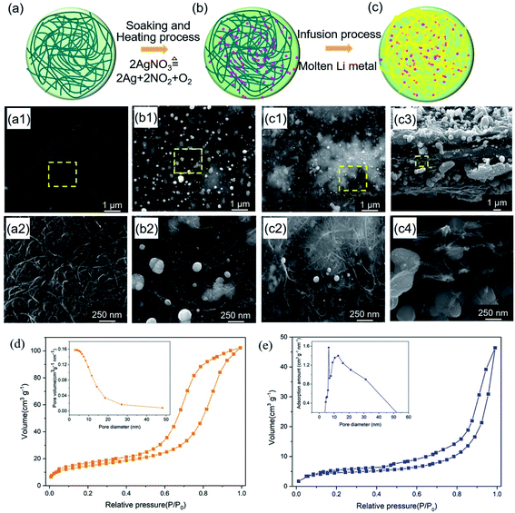
Herein, a 3D interconnected carbon nanotube (CNT) film decorated with Ag nanoparticles for a high-performance lithium host has been prepared by a facile soaking and heating method. As depicted in Fig. 1, Ag+ and NO3− are uniformly absorbed on the surface of a CNT film during the soaking process and then transformed into ultrafine Ag nanoparticles via the thermal decomposition of silver nitrate (AgNO3) at 300 °C in an inert atmosphere during the heating process. Then, the CNT/Ag film is employed as a host for the Li metal anode by simply infusing molten Li without any further structural modification. Since the deposition of Li+ is guided by Ag nanoparticles and ample supply of electrons via carbon nanotube channels, the CNT/Ag/Li film exhibits a lower voltage hysteresis and enhanced cycling stability of the Li symmetrical cells: voltage hysteresis of ∼30 mV with a lifetime of 400 h.
Experimental
Preparation of CNT/Ag/Li film
The commercially activated carbon nanotube film (CNT), provided by Chengdu Organic Chemicals Co., Ltd, was rinsed several times in an HNO3 solution (0.1 wt%) and then soaked in a silver nitrate solution (1 mg mL−1) for 10 min. The wet CNT film was dried in an oven at 70 °C for 4 h, followed by heated at 300 °C for another 2 h in a pure N2 atmosphere at a heating rate of 5 °C min−1 to obtain the 3D Ag nanoparticle-decorated CNT (CNT/Ag) film. Later, the black-colored CNT/Ag film was placed in a molten Li solution at 320 °C in a glovebox and quickly transformed into the silver-colored CNT/Ag/Li film within a few minutes. Finally, the CNT/Ag/Li film was obtained after cooling to room temperature.Characterization and measurements
The morphologies, structures, and chemical element mapping of the samples were observed on a field-emission scanning electron microscope (FESEM) (JEM-2100F, JEOL, Japan). In order to visualize the volume change after cycling, the CNT/Ag/Li film obtained from the disassemble symmetrical cells after 200 cycles was rinsed with dimethyl carbonate before cutting into halves in a glove box. The samples were dried in a vacuum oven to expose the cross-section for SEM imaging. The surface area and pore distribution of the samples were measured by nitrogen adsorption–desorption measurements (ASAP 2460). The chemical structure and composition of the samples were determined via X-ray photoelectron spectroscopy (XPS) (ESCALAB 250XI) equipped with an Al Kα achromatic X-ray source. A LANS-CT2001A battery test system and Arbin BT2000 appliances were used to test the symmetrical cells. Electrochemical impedance spectroscopy (EIS) tests on the symmetrical cells were performed on a PARSTAT 2273 Electrochemical System (Princeton) over a frequency range from 10 mHz to 1 MHz by applying an AC signal of 10 mV.For the electrochemical performances of the symmetrical cells, CR2032-type coin cells assembled with two CNT/Ag/Li electrodes (11 mm in diameter) and a polypropylene film (Celgard 2400) were used. The electrolyte for the symmetrical cells was commercial 1 M lithium bis(trifluoromethanesulfonyl)imide (LiTFSI) in a mixed solution of 1,3-dioxolane (DOL) and 1,2-dimethoxyethane (DME) with a volume ratio of 1![[thin space (1/6-em)]](https://www.rsc.org/images/entities/char_2009.gif) :
:![[thin space (1/6-em)]](https://www.rsc.org/images/entities/char_2009.gif) 1. The cycling stability of the Li symmetrical cells was tested at 1.0 mA cm−2 at an areal capacity of 1.0 mA h cm−2 by recording the variation of voltage hysteresis. The full cells paired with sulfur/C were charged/discharged at a voltage window of 1.7 to 2.8 V and 0.5C (1C = 1650 mA g−1).
1. The cycling stability of the Li symmetrical cells was tested at 1.0 mA cm−2 at an areal capacity of 1.0 mA h cm−2 by recording the variation of voltage hysteresis. The full cells paired with sulfur/C were charged/discharged at a voltage window of 1.7 to 2.8 V and 0.5C (1C = 1650 mA g−1).
Results and discussion
The fabrication process of the free-standing lithiophilic CNT/Ag/Li film contained three steps (Fig. 1): (1) absorption of AgNO3 into CNT film; (2) thermal decomposition of AgNO3 to Ag nanoparticles; (3) thermal infusion of molten Li to form the CNT/Ag/Li film. Before absorption, the CNT film is soaked in a HNO3 solution (1 wt%) for 10 min to enable more adsorption sites for Ag+ and NO3− (Fig. 1a). As shown in Fig. 1a1 and a2, the CNT film comprises multi-walled-CNT (MWCNT) bundles with diameters between 10 nm to 30 nm. Many porous gaps (dozens of nanometers) are distributed between the carbon nanotubes, which can accommodate metallic Li storage. Moreover, the cross-sectional CNT film is a three-layered structure with a dense top and a bottom layer and a loose middle layer (Fig. S1†), which can provide a porous space for Li infusing. After the adsorption of silver nitrate for 30 min and heating at 300 °C in an inert atmosphere for 2 h, the 3D porous CNT/Ag film, with well-distributed Ag nanoparticles, is formed. During the heating process, the sorptive silver nitrate on the CNT film decomposes into Ag nanoparticles, NO2, and O2, and results in the random dispersion of Ag nanoparticles among the CNT film. Scanning electron microscopy (SEM) images of the top surface of the CNT/Ag film show that Ag nanoparticles, with wide sizes of 50–320 nm, are tightly absorbed on the top surface (Fig. 1b1 and b2), which is beneficial for enhancing the lithiophilicity of the CNT film.33Thereafter, molten Li is infused into the CNT/Ag film at 320 °C in an inert atmosphere. The optical photograph in Fig. S2a† shows that the CNT film without Ag nanoparticles cannot infuse molten Li metal. In contrast, the CNT/Ag film with good lithiophilicity can enable the rapid incorporation of Li metal in a few minutes (Fig. S2b†), since the Ag nanoparticles can react with molten Li to form LixAg.34 In the CNT/Ag/Li film, voids and nanotubes in the formed film are filled with Li metal, as illustrated in Fig. 1c. It should be mentioned that the infusion content of Li metal immobilized on the CNT/Ag/Li film is controllable. When the CNT/Ag film is in contact with molten Li side-on (Fig. 1c1), molten Li can be uniformly infused into the surface of a MWCNT channel. Moreover, voids between the carbon nanotubes on the surface and the cross sections are still persevered after Li incorporation (Fig. 1c2 and c3), which could facilitate the infiltration of electrolytes into the CNT/Ag/Li film and generate more electrolyte infiltration pathways during the Li stripping process.31 Notably, the thickness of the CNT/Ag/Li film (∼6.5 μm) is slightly different when compared with the CNT film (6.1 μm), indicating that the Li metal is primarily dispersed along the surface and in the voids of the CNT/Ag film. From the high magnification SEM image of the cross-sectional CNT/Ag/Li film (Fig. 1c4), the inner nanotubes exhibit homogeneous Ag nanoparticles dispersed in the voids and on the surface of the carbon nanotubes, which are beneficial to guide the Li deposition behavior. When pouring molten Li onto the CNT/Ag/Li film, all of the voids on the surface and cross side can be infused with molten Li (Fig. S3†). Furthermore, as can be seen in Fig. 1d, the CNT/Ag film shows a porous structure with a surface area, pore volume, and pore size of 52.0663 m2 g−1, 0.158203 cm3 g−1, and 12.1539 nm, respectively. After the incorporation of molten Li, most of the Li metal is dispersed along the surface and in the voids of the CNT/Ag film, the formed CNT/Ag/Li film shows a relatively dense surface with a deceased surface area of 15.3405 m2 g−1, a decreased pore volume of 0.071738 cm3 g−1, and an increased pore size of 18.7054 nm (Fig. 1e). The increased pore size of the CNT/Ag/Li film mainly results from the expansion of its three-layered structure during the incorporation process of molten Li, which is in accordance with the slightly increased thickness of the CNT/Ag/Li film when compared to that of the CNT/Ag film.
In addition, the energy dispersive spectrometry (EDS) mapping of the CNT/Ag film has been further characterized to investigate the distribution of the Ag element (Fig. 2a). The pink, red, and black-green dots in Fig. 2a1–a3 apparently represent the Ag, C, and O elements. The top and bottom surface of the CNT/Ag film are mainly composed of pink dots, indicating that a thick Ag layer is formed on the surface of the CNT/Ag film (Fig. 2a1). A high intensity of red dots and a low intensity of pink dots are observed in the cross section of the CNT/Ag film, reflecting that the middle cross-section of the CNT/Ag film is composed of CNT with a random dispersion of Ag nanoparticles (Fig. 2a2). Moreover, black green dots exist along the whole cross-section (Fig. 2a3), which may result from the formed interaction between Ag and carbon via an Ag–O–C bond. The above results demonstrate that Ag nanoparticles converted from AgNO3 can be distributed not only on the surface but also in the inner space of the CNT/Ag film, which helps in the regulation of Li plating/stripping behavior.
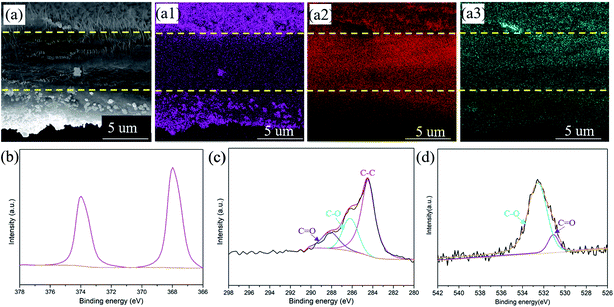 | ||
| Fig. 2 The cross-sectional SEM image of the CNT/Ag film (a) and the corresponding elemental mapping of Ag (a1), C (a2), and O (a3). XPS spectra of Ag 3d (b), C 1s (c), and O 1s (d). | ||
The chemical structure and composition of the CNT/Ag films are also investigated by XPS (Fig. 2b–d). Significant peaks for the Ag, C, O, and N elements exist in the CNT/Ag film (Fig. S4†). Specifically, in the Ag 3d region (Fig. 2b), two sharp peaks related to Ag 3d5/3 and Ag 3d2/3 at 368.4 eV and 374.4 eV exist, which verify that the Ag nanoparticles decorated on the surface of the CNT/Ag film are in the metallic state.35 For C 1s (Fig. 2c), three peaks at 284.6 eV, 286.1 eV, and 288.6 eV correspond to the C–C groups of amorphous carbon and the C–O and C![[double bond, length as m-dash]](https://www.rsc.org/images/entities/char_e001.gif) O groups of residual oxygenated functional groups after the thermal decomposition of AgNO3, respectively. For O 1s (Fig. 2d), two peaks at 531.0 eV and 532.5 eV are attributed to Ag–O/C–O and C
O groups of residual oxygenated functional groups after the thermal decomposition of AgNO3, respectively. For O 1s (Fig. 2d), two peaks at 531.0 eV and 532.5 eV are attributed to Ag–O/C–O and C![[double bond, length as m-dash]](https://www.rsc.org/images/entities/char_e001.gif) O bonds, respectively, indicating strong interactions between the Ag nanoparticles and carbon nanotubes.
O bonds, respectively, indicating strong interactions between the Ag nanoparticles and carbon nanotubes.
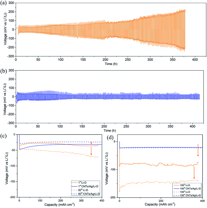
The cycling performance has been evaluated using the charge–discharge mode at a current density of 1 mA cm−2 and cyclic capacity of 1 mA h cm−2 (Fig. 3). The standard CR2025 type symmetrical cells have been assembled with two CNT/Ag/Li electrodes. For comparisons, two bulk Li foils were used to assemble the coin symmetrical cells in a glovebox under the same conditions. For the bulk Li electrode, the voltage hysteresis of bulk Li increases from the initial 80 mV to 400 mV after over 200 cycles (Fig. 3a). The rapid increase in the voltage hysteresis demonstrates unfavorable Li nucleation on bulk Li, which causes high resistance and cell failure.31 However, for the CNT/Ag/Li electrode, the corresponding voltage hysteresis is stabilized at 40 mV (−20 mV to 20 mV) (Fig. 3b). This improved stability results from the random dispersion of Ag nanoparticles as nanodots for guiding Li nucleation as well as the support of a highly conductive carbon nanotube matrix for effective facilitation of electron transfer during the plating/stripping process.
Nucleation overpotential is the voltage variation between the sharp dip voltage and the flat plateau voltage during the Li plating process.25 A high nucleation overpotential means a high nucleation barrier. To illustrate the effect of Ag nanoparticles, voltage–time profiles of the CNT/Ag/Li electrode on 1st, 50th, 100th, and 150th cycles are employed and compared with bulk Li foil. As shown in Fig. 3c and d, for bulk Li, the plating process of Li shows apparent nucleation overpotentials on the 1st, 50th, 100th and 150th cycles. However, Li nucleation on the CNT/Ag/Li film displays a smaller but still obvious overpotential in the plating process on the 1st cycle, indicating much easier and uniform nucleation of Li plating. Moreover, when cycled for the 50th, 100th, and 150th cycles, the nucleation overpotentials of the CNT/Ag/Li electrode are negligible, indicating the uniform deposition of the Li metal. In addition, the voltage–time profile of the CNT/Ag/Li electrode at the 100th and 150th cycles nearly shows the same, which means superior cycling stability. Significantly, for the CNT/Ag/Li electrode, the voltage hysteresis slightly decreases from ∼60 mV at the 1st cycle to ∼50 mV at the 50th cycle, and finally decreases to ∼40 mV at the 100th and 150th cycles, indicating a much more stable SEI interface and much fewer side reactions. The superior cycling stability of CNT/Ag/Li is due to its porous and highly conductive network, which reduces the local current density for Li-plating/stripping. According to the Sand's law, the 3D porous CNT/Ag/Li film with a random dispersion of Ag nanoparticles can restrict the formation of Li dendrites and improve the cycling stability.
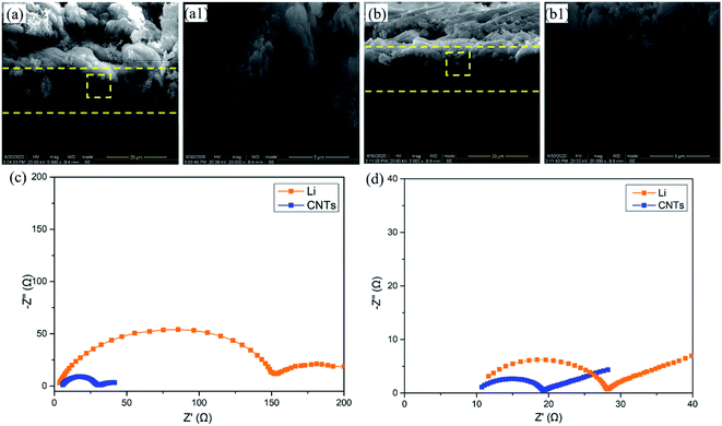
In order to investigate the volume change after cycling, the CNT/Ag/Li electrodes before and after 200 cycles are observed. Before cycling (Fig. 4a), the CNT/Ag/Li electrode shows a porous cross-sectional structure with a three-layered structure, and the incorporated Li metal in the inner place of the cross section shows a loose structure with many stacked spherical Li nanoparticles. In contrast, after 200 cycles (Fig. 4b), the CNT/Ag/Li electrode shows a dense and uniform cross-sectional structure with an integrated one-layer structure and most of the Li metal is distributed in the inner layer. Importantly, the thickness of the CNT/Ag/Li electrode before and after 200 cycles shows a negligible change (from 14.8 μm to 15.0 μm), indicating its superior structural stability. Moreover, the deposited Li metal on CNT/Ag/Li shows a spherical shape without any dendrites, which may result from the high lithiophilicity of the Ag nanoparticle seeds and the highly conductive matrix. The above results are also in accordance with the long-term cycling stability tests. In order to better understand the interfacial kinetics, electrochemical impendence spectroscopy (EIS) was performed on the anode electrodes of the bulk Li foil and CNT/Ag/Li films before cycling and after the 200th cycle. Before cycling (Fig. 4c), the EIS spectrum of the CNT/Ag/Li anode shows that the charge-transfer resistance (Rct) at the Li–CNT/Ag/Li interface is much smaller than that of bulk Li foil, which suggests that the CNT/Ag/Li electrode benefits from the Li plating/stripping reaction by enabling faster kinetics. After the 200th cycles (Fig. 4d), the charge-transfer impedance of CNT/Ag/Li remains smaller than that of bulk Li, which originated from the seeded nucleation of Li on the Ag nanoparticles and reversible dissolution.
The electrochemical performance of the CNT/Ag/Li anodes was evaluated in a Li–S full cell. For the CNT/Ag/Li anode (Fig. 5a), the full cell presents a high capacity of ∼796 mA h g−1 at 0.5C. After 100 cycles, the cycling capacity of the full cell could also reach ∼654 mA h g−1, which shows a high coulombic efficiency of 82%. Moreover, the CNT/Ag/Li anode enables stable and highly reversible charge and discharge plateaus as compared to that of pure the Li anode and CNT/Ag/Li exhibits a much lower voltage polarization than that of pure the Li anode counterparts (Fig. 5b), indicating the significantly improved kinetics. Therefore, the formed CNT/Ag/Li electrode is able to couple with the sulfur/C cathode.
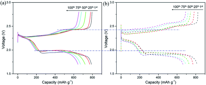 | ||
| Fig. 5 Galvanostatic charge–discharge curves of the CNT/Ag/Li anode (a) and the pure Li anode (b) in the Li–S full cell at 0.5C. | ||
Conclusions
In summary, three-dimensional (3D) porous carbon nanotube films decorated with Ag nanoparticles have been successfully fabricated using a facile soaking and heating method, and can be used as a lithium metal-based anode by the thermal infusion of Li metal. The highly conductive carbon nanotubes can effectively facilitate electron transfer during the plating/stripping process. Moreover, the decorated Ag nanoparticles can effectively improve the lithiophilicity of Li and regulate the Li plating/stripping process with negligible dendrite growth. As a result, a long-term cycling stability with a relatively low voltage hysteresis at 1.0 mA h cm−2 is obtained for more than 400 h and promising cycling stability of the full cell paired with a sulfur/C cathode is also observed. Our work provides a facile strategy for the construction of Li host materials as a dendrite-free Li-metal anode for next generation high energy batteries.Conflicts of interest
The authors declare no competing financial interest.Acknowledgements
This work was supported by the financial support from the startup funds from the University of Electronic Science and Technology of China (Y030202059018003).Notes and references
- Y. X. Gu, Y. X. Xuan, H. Zhang, X. Y. Deng, Y. H. Sun and L. Wang, Dalton Trans., 2019, 48, 10604 RSC.
- J. Liu, Z. N. Bao, Y. Cui, E. J. Dufek, J. B. Goodenough, P. Khalifah, Q. Y. Li, B. Y. Liaw, P. Liu, A. Manthiram, Y. S. Meng, V. R. Subramanian, M. F. Toney, V. V. Viswanathan, M. S. Whittingham, J. Xiao, W. Xu, J. h. Yang, X. Q. Yang and J. G. Zhang, Nat. Energy, 2019, 4, 180–186 CrossRef CAS.
- Y. B. He, Y. Qiao and H. S. Zhou, Dalton Trans., 2018, 47, 6881 RSC.
- J. H. Park, J. H. Park, A. H. Jeong, H. N. Han and J. Mun, Electrochim. Acta, 2018, 282, 582–587 CrossRef CAS.
- J. Mun, H. W. Ha and W. Choi, J. Power Sources, 2014, 251, 386–392 CrossRef CAS.
- T. Huang, J. K. Lee, J. Mun and W. Choi, J. Power Sources, 2016, 322, 40–48 CrossRef.
- J. Mun, J. H. Park, W. Choi, A. Benayad, J. H. Park, J. M. Lee, S. G. Doo and S. M. Oh, J. Mater. Chem. A, 2014, 2, 19670–19677 RSC.
- R. H. Wang, W. S. Cui, F. L. Chu and F. X. Wu, J. Energy Chem., 2020, 48, 145–159 CrossRef.
- Y. G. Lee, S. Fujiki, C. Jung, N. Suzuki, N. Yashiro, R. Omoda, D. S. Ko, T. Shiratsuchi, T. Sugimoto, S. Ryu, J. H. Ku, T. Watanabe, Y. Park, Y. Aihara, D. Im and I. T. Han, Nat. Energy, 2020, 5, 299–308 CrossRef CAS.
- C. P. Yang, Y. G. Yao, S. M. He, H. Xie, E. Hitz and L. B. Hu, Adv. Mater., 2017, 29, 1702714 CrossRef PubMed.
- Z. W. Sun, S. Jin, H. C. Jin, Z. Z. Du, Y. W. Zhu, A. Y. Cao, H. X. Ji and L. J. Wan, Adv. Mater., 2018, 30, 1800884 CrossRef.
- Z. Y. Yao, W. S. Jia, Z. H. Wang, J. Ruan, X. G. Kong, X. Guan, Z. H. Wang, J. Z. Li, Y. Wang, W. Zou and F. Zhou, J. Energy Chem., 2020, 51, 285–292 CrossRef.
- J. X. Zheng, M. S. Kim, Z. Y. Tu, S. Choudhury, T. Tang and L. A. Archer, Chem. Soc. Rev., 2020, 49, 2701 RSC.
- K. H. Chen, K. N. Wood, E. Kazyak, W. S. LePage, A. L. Davis, A. J. Sanchez and N. P. Dasgupta, J. Mater. Chem. A, 2017, 5, 11671–11681 RSC.
- W. Xu, J. Wang, F. Ding, X. Chen, E. Nasybulin, Y. Zhang and J. G. Zhang, Energy Environ. Sci., 2014, 7, 513–537 RSC.
- H. Ye, Y. X. Yin, S. F. Zhang, Y. Shi, L. Liu, X. X. Zeng, R. Wen, Y. G. Guo and L. J. Wan, Nano Energy, 2017, 36, 411–417 CrossRef CAS.
- D. Wang, W. Zhang, W. Zheng, X. Cui, T. Rojo and Q. Zhang, Adv. Sci., 2017, 4, 1600168 CrossRef PubMed.
- S. P. Li, S. Fang, H. Dou and X. G. Zhang, ACS Appl. Mater. Interfaces, 2019, 11, 20804–20811 CrossRef CAS PubMed.
- N. W. Li, Y. X. Yin, C. P. Yang and Y. G. Guo, Adv. Mater., 2016, 28, 1853–1858 CrossRef CAS PubMed.
- J. Jie, Y. L. Liu, L. Cong, B. H. Zhang, W. Lu, X. M. Zhang, J. Liu, H. M. Xie and L. Q. Sun, J. Energy Chem., 2020, 49, 80–88 CrossRef.
- D. M. Kang, K. Tang, J. Koh, W. B. Liang and J. P. Lemmon, J. Energy Chem., 2020, 44, 68–72 CrossRef.
- C. P. Yang, Y. X. Yin, S. F. Zhang, N. W. Li and Y. G. Guo, Nat. Commun., 2015, 6, 8058 CrossRef CAS PubMed.
- J. L. Lang, J. N. Song, L. H. Qi, Y. Z. Luo and H. Wu, ACS Appl. Mater. Interfaces, 2017, 9, 10360–10365 CrossRef CAS PubMed.
- Y. J. Zhang, S. F. Liu, X. L. Wang, Y. Zhong, X. H. Xia, J. B. Wu and J. P. Tu, J. Power Sources, 2018, 374, 205–210 CrossRef CAS.
- Q. D. Sun, W. Zhai, G. M. Hou, J. K. Feng, L. Zhang, P. C. Si, S. R. Guo and L. J. Ci, ACS Sustainable Chem. Eng., 2018, 6, 15219–15227 CrossRef CAS.
- R. Zhang, X. R. Chen, X. Chen, X. B. Cheng, X. Q. Zhang, C. Yan and Q. Zhang, Angew. Chem., Int. Ed., 2017, 56, 7764–7768 CrossRef CAS PubMed.
- G. Y. Zheng, S. W. Lee, Z. Liang, H. W. Lee, K. Yan, H. B. Yao, H. T. Wang, W. Y. Li, S. Chu and Y. Cui, Nat. Nanotechnol., 2014, 9, 618–623 CrossRef CAS PubMed.
- A. M. Hafez, Y. Jiao, J. Shi, Y. Ma, D. Cao, Y. Liu and H. Zhu, Adv. Mater., 2018, 30, 1802156 CrossRef PubMed.
- Z. Li, J. Huang, B. Y. Liaw, V. Metzler and J. Zhang, J. Power Sources, 2014, 254, 168–182 CrossRef CAS.
- W. Deng, W. H. Zhu, X. F. Zhou, X. Q. Peng and Z. P. Liu, ACS Appl. Mater. Interfaces, 2018, 10, 20387–20395 CrossRef CAS PubMed.
- S. Jadhav, G. M. Thorat, J. Mun and J. G. Seo, J. Power Sources, 2016, 302, 12–31 CrossRef.
- K. Yan, Z. Lu, H. W. Lee, F. Xiong, P. C. Hsu, Y. Li, J. Zhao, S. Chu and Y. Cui, Nat. Energy, 2016, 1, 16010 CrossRef CAS.
- R. Zhang, X. R. Chen, X. Chen, X. B. Cheng, X. Q. Zhang, X. R. Chen, X. B. Cheng, C. Yan, C. Z. Zhao and Q. Zhang, Joule, 2018, 2, 746–777 Search PubMed.
- G. Taillades and J. Sarradin, J. Power Sources, 2004, 125, 199–205 CrossRef CAS.
- K. Wang and J. G. Huang, J. Phys. Chem. Solids, 2019, 126, 155–163 CrossRef CAS.
Footnote |
| † Electronic supplementary information (ESI) available. See DOI: 10.1039/d0ra04579a |
| This journal is © The Royal Society of Chemistry 2020 |

