 Open Access Article
Influence of surface coating on the microstructures and dielectric properties of BaTiO3 ceramic via a cold sintering process†
Shenglin Kangac,
Hongxia Guo*a,
Jinbin Wangc,
Xiangli Zhong c and
Bo Li
 *bd
*bd
aState Key Laboratory of Intense Pulsed Radiation Simulation and Effect (Northwest Institute of Nuclear Technology), Xi'an, 710024, China. E-mail: guohxnint@126.com
bScience and Technology on Reliability Physics and Application Technology of Electronic Component Laboratory, 510610, China. E-mail: bli@xtu.edu.cn
cSchool of Materials and Engineering, Xiangtan University, Xiangtan 411105, Hunan, China
dDepartment of Materials Science and Engineering, Southern University of Science and Technology, Shenzhen, 518055, China
First published on 20th August 2020
Abstract
We present herein a modified cold sintering process (CSP) for BaTiO3 ceramics using a surface coating at the particle surface which could enhance the relative density of BaTiO3 up to ∼93.5% at 220 °C and 500 MPa. The surface coating greatly enhances the ceramic density, mainly because it facilitates the dissolution–precipitation process during CSP. Ba vacancies form at the surface of the coated powders, so Ba(OH)2 solution is used to compensate Ba ions in the as-cold-sintered ceramics, which increases the dielectric permittivity. Post-annealing at 700 and 900 °C increases the relative density to 97%, and the resulting relative dielectric permittivities are 810 and 1550, respectively, at room temperature and 1 kHz. This technique may also be extended to materials with very small, incongruent solubility in water or volatile solutions that use the cold sintering process.
1. Introduction
Sintering is one of the major processes for densifying ceramics and involves exposing a powder to high temperatures to densify it into a dense bulk ceramic.1–3 The sintering process generally requires temperatures of up to 1000 °C for many oxides materials.1,4 Obtaining such high sinter temperatures takes a long time and is an energy-consuming process that involves a complicated heating system. Therefore, numerous new sintering technologies have been developed over the past several decades to reduce the processing temperature. These technologies, such as liquid-phase sintering,5 microwave sintering,6 spark plasma sintering,7 flash sintering,8 and high-pressure sintering,9 lower the sintering temperature somewhat, although it still remains above 400 °C.Recently, a novel sintering method called the “cold sintering process” (CSP) has been developed for making dense ceramics from a wide range of functional oxides and at low sintering temperature (<300 °C).10–16 The CSP uses a small quantity of aqueous solution as a transient solvent under uniaxial pressure. The densification of ceramic particles during the CSP is mainly due to a liquid-phase-induced dissolution-precipitation process: the solid surfaces decompose and partially dissolve in the liquid phase, following which heating leads to evaporation, which creates a supersaturated state for precipitation. The rearrangement of the solid particles and the redistribution of the liquid phase kinetically benefit the densification under certain temperature and pressure.14,17,18 The dissolution of ceramic particles in the aqueous solution plays a key role during the CSP. For materials that can be dissociated in water, the CSP has already been used to obtain dense ceramics, such as Li2MoO4,13 NaNO2,4 KH2PO4,4 NaCl,13 ZnO,10 HBO2-II,19 etc. For stable materials that generally dissolve incongruently in water, a proactive mixture of solvochemical solutions must be used.12,15,16 In addition, it's also a research hotspot to fabricate novel composite ceramics through the CSP, such as microwave composite ceramics with high quality factors for wireless and satellite communication technology,17–21 three-dimensionally (3D) integrated multilayer ceramic capacitors with alternating ceramic and metal electrode layers,22 and novel dielectric materials with fast signal response performance that meets the requirements of the rapid development of the fifth-generation mobile cellular network (5G).23,24 To obtain dense barium titanate (BaTiO3) ceramics, a water-based suspension of Ba(OH)2 and TiO2 was used to avoid incongruent dissolution of BaTiO3 during the CSP.4,12 In addition, the hydrothermal precursor solutions were also used in the preparation of BaTiO3 ceramics during the CSP.25 A Pb(NO3)2 solution was used by Wang et al. as the transient liquid phase to densify Pb(Zr,Ti)O3 ceramics.15 In addition, Boston et al. developed a method to induce the chloride-TiO2 reaction in SrTiO3 particles to create fully dense ceramics, and followed by heating at 950 °C.16 The result was a well-densified ceramic with excellent dielectric characteristics.
The surface state of the particle is important for the particle-compaction process of the CSP.4 From this point of view, it is reasonable to believe that a surface coating, which has been widely used over the past decades to promote sintering in conventional sintered ceramics and leads to favorable ceramic properties, should be a good way to improve the properties of ceramics obtained from the CSP.26,27 The surface coating can modify the surface characteristics of the particles and distribute the sintering aids uniformly within the green bodies. During the CSP, the ultrathin surface coating (thickness is several nanometers) should have high reactivity with the aqueous solution used in the sintering process.
In this work, we propose a method of applying a surface coating to the powder surface of materials that dissolve incongruently in aqueous solutions. The hydrothermal synthesized BaTiO3 particles are coated by sol-precipitation methods. Next, a typical CSP is used to obtain a dense BaTiO3 ceramics. This work compares the densities and the dielectric properties of a surface-coating-assisted CSP. The main objective of this work is to explore the coating method to enhance the BaTiO3 ceramic density by using the CSP. The results show that this coating method has the potential to extend the CSP to materials that undergo incongruent dissolution.
2. Experimental
2.1 Materials
Ba(OH)2·8H2O and Ba(OAc)2 was purchased from Sinopharm Group Chemical Reagent Co., Ltd., China. Tetrabutyl titanate and 2-methoxyethanol was purchased from Kermel Chemical Reagent Co., Ltd., China. Other chemicals were purchased from Xilong Chemical Co., Ltd., China. All chemical reagents are analytical reagent. The water used in the experiment is the ultra-pure water.2.2 Hydrothermal synthesis
The BaTiO3 powders were prepared by using a hydrothermal process. Ba(OH)2·8H2O was dissolved in deionized water at 90 °C and tetrabutyl titanate (molar ratio of Ba/Ti = 1/1) was dissolved in ethanol absolute, and the two solutions were mixed by stirring. Adding the ammonia water (25%) dropwise to the mixed solution created copious white precipitation. The slurries were transferred into a Teflon-lined autoclave and kept at a filling ratio of 60% (v/v). The autoclave was sealed and heated at 200 °C for 48 h. After hydrothermal treatment, the reactor was allowed to cool to room temperature. The samples were collected and washed with deionized water and ethanol, and then dried at 80 °C in air for 12 h.2.3 Surface coating
Three types of BaTiO3 precursor solutions were prepared by dissolving Ba(OAc)2 and tetrabutyl titanate at ratios Ba![[thin space (1/6-em)]](https://www.rsc.org/images/entities/char_2009.gif) :
:![[thin space (1/6-em)]](https://www.rsc.org/images/entities/char_2009.gif) Ti = 1
Ti = 1![[thin space (1/6-em)]](https://www.rsc.org/images/entities/char_2009.gif) :
:![[thin space (1/6-em)]](https://www.rsc.org/images/entities/char_2009.gif) 1, 2
1, 2![[thin space (1/6-em)]](https://www.rsc.org/images/entities/char_2009.gif) :
:![[thin space (1/6-em)]](https://www.rsc.org/images/entities/char_2009.gif) 1, and 3
1, and 3![[thin space (1/6-em)]](https://www.rsc.org/images/entities/char_2009.gif) :
:![[thin space (1/6-em)]](https://www.rsc.org/images/entities/char_2009.gif) 1 with a solvent of acetic acid and 2-methoxyethanol. The BaTiO3 powders were dispersed by stirring in the solvent of acetic acid and 2-methoxyethanol, and then 5, 10, 20 mol% BaTiO3 precursor solutions were added. To this was added ammonia water (25%) with a volume 1.5 times that of the solvent. The suspensions were evaporated at 90 °C, and then dried at 120 °C for 12 h. The resulting powders were calcined at 600 °C for 2 h.
1 with a solvent of acetic acid and 2-methoxyethanol. The BaTiO3 powders were dispersed by stirring in the solvent of acetic acid and 2-methoxyethanol, and then 5, 10, 20 mol% BaTiO3 precursor solutions were added. To this was added ammonia water (25%) with a volume 1.5 times that of the solvent. The suspensions were evaporated at 90 °C, and then dried at 120 °C for 12 h. The resulting powders were calcined at 600 °C for 2 h.
2.4 Ceramic processing
For the CSP, the as-prepared powders were mixed 1–2 min with 30 wt% deionized water or Ba(OH)2 solution by using a pestle and mortar. The mixture was uniaxially pressed under 500 MPa first at room temperature for 10 min, and then at 220 °C. This temperature was maintained for 1.5 h. The as-prepared ceramic pellets were baked at 200 °C overnight to remove possible water residue. And then the ceramic pellets were further annealed at 700 and 900 °C for 3 h with a temperature ramp rate of 10 °C min−1 in air. The densities were measured by using Archimedes' method, with ethanol as liquid medium.2.5 Characterization
The phase structures of the specimen were determined by using X-ray diffraction (XRD, Rigaku D/max-rA), and the powders were imaged by using a transmission electron microscope (TEM, JEM-2100). To prepare the TEM samples, the powders were dispersed ultrasonically in ethanol for 20 min. The fracture surfaces of the ceramics were imaged by using a field-emission scanning electron microscope (Quanta FEG). The surface chemical composition of the powders was determined by using X-ray photoelectron spectroscopy (XPS; Thermo ESCALAB 250XI) with Al Kα emission. The binding energies and oxidation states were obtained from high-resolution scans. The energy scale was calibrated by assigning 284.8 eV to the C 1s peak, which corresponds to adventitious carbon. For dielectric measurements, platinum electrodes were fabricated by sputtering, and the dielectric properties were measured at 1–100 kHz by using a LCR meter (E4980A, Agilent Technologies) as the sample was cooled from 200 °C to room temperature at a rate of 2 °C min−1.3. Results and discussions
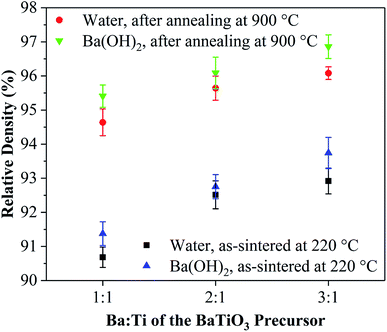
To exclude the effect of calcination, the hydrothermal synthesized powders without coating were calcined at 600 °C for 2 h, and the ceramics were prepared by using the CSP. By applying water solution, relative densities of 70% and 65% were obtained for the ceramic made from the hydrothermal synthesized powders and the hydrothermal synthesized powders calcined at 600 °C, respectively. We adopted a theoretical density of 6.02 g cm−3 for the BaTiO3 ceramics. Adding a few drops of water during the CSP did not help densify the uncoated BaTiO3 powder into a dense ceramic. The BaTiO3 ceramics were then made from the coated powders. Table 1 shows the coating conditions, the liquid phase conditions, and the corresponding abbreviations of the coated powders and ceramics. Fig. 1 shows the densities of the cold-sintered BaTiO3 ceramics made by using the various coated powders. Upon applying just a few drops of water, the relative densities of the BaTiO3 ceramics prepared from coated powders increases to 90% and upwards.| Coating condition | Abbreviation | Liquid phase | Ceramic | |
|---|---|---|---|---|
Ba![[thin space (1/6-em)]](https://www.rsc.org/images/entities/char_2009.gif) : :![[thin space (1/6-em)]](https://www.rsc.org/images/entities/char_2009.gif) Ti of the BaTiO3 precursor Ti of the BaTiO3 precursor |
The mole fraction of BaTiO3 precursor (mol%) | |||
1![[thin space (1/6-em)]](https://www.rsc.org/images/entities/char_2009.gif) : :![[thin space (1/6-em)]](https://www.rsc.org/images/entities/char_2009.gif) 1 1 |
5 | 1–5 | Water | W1–5 |
1![[thin space (1/6-em)]](https://www.rsc.org/images/entities/char_2009.gif) : :![[thin space (1/6-em)]](https://www.rsc.org/images/entities/char_2009.gif) 1 1 |
5 | 1–5 | Ba(OH)2 | S1–5 |
1![[thin space (1/6-em)]](https://www.rsc.org/images/entities/char_2009.gif) : :![[thin space (1/6-em)]](https://www.rsc.org/images/entities/char_2009.gif) 1 1 |
10 | 1–10 | Water | W1–10 |
1![[thin space (1/6-em)]](https://www.rsc.org/images/entities/char_2009.gif) : :![[thin space (1/6-em)]](https://www.rsc.org/images/entities/char_2009.gif) 1 1 |
20 | 1–20 | Water | W1–20 |
2![[thin space (1/6-em)]](https://www.rsc.org/images/entities/char_2009.gif) : :![[thin space (1/6-em)]](https://www.rsc.org/images/entities/char_2009.gif) 1 1 |
5 | 2–5 | Water | W2–5 |
2![[thin space (1/6-em)]](https://www.rsc.org/images/entities/char_2009.gif) : :![[thin space (1/6-em)]](https://www.rsc.org/images/entities/char_2009.gif) 1 1 |
5 | 2–5 | Ba(OH)2 | S2–5 |
3![[thin space (1/6-em)]](https://www.rsc.org/images/entities/char_2009.gif) : :![[thin space (1/6-em)]](https://www.rsc.org/images/entities/char_2009.gif) 1 1 |
5 | 3–5 | Water | W3–5 |
3![[thin space (1/6-em)]](https://www.rsc.org/images/entities/char_2009.gif) : :![[thin space (1/6-em)]](https://www.rsc.org/images/entities/char_2009.gif) 1 1 |
5 | 3–5 | Ba(OH)2 | S3–5 |
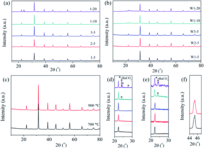
The phase structures of the hydrothermal synthesized powders and the hydrothermal synthesized powders calcined at 600 °C [Fig. S1(a), ESI†] are well indexed as perovskite structures of BaTiO3, and no other impurities appear. In addition, the BaTiO3 powders have a light peak splitting at ∼45°, which indicates a part of the tetragonal phase; after calcining, part of the cubic phase forms [Fig. S1(b), ESI†]. Fig. 2 shows the phase structures of the BaTiO3 powders and ceramics. The phase structures of the coated powders of 1–5, 2–5, 3–5, 1–10, and 1–20 are displayed in Fig. 2(a). Details in the range 20°–24° are magnified in Fig. 2(d) for ease of viewing. The powders 1–5, 2–5, and 3–5, which were coated by the BaTiO3 precursor with a lower mole fraction, are well indexed as BaTiO3, and no impurity phase appears in the XRD pattern. When the mole fraction of BaTiO3 precursor increases to 10%, a small amount of impurity phase (∼24°) of BaCO3 is detected, as shown in Fig. 2(d). Fig. 2(d) also reveals an increase in the impurity phase of BaCO3 as the mole fraction increases to 20%, which we explain as follows: In the barium species, Ba2+ reacts with environmental CO2 at low temperatures.28 During the precipitation of the surface coating, the hydroxyl precipitation of barium and titanium coat the surface of the BaTiO3 particles. When the suspensions are evaporated at 90 °C or dried at 120 °C, barium precipitate can react with CO2 in air to form BaCO3 since hydroxides are extremely sensitive to CO2.28 Note that BaCO3 increases as the mole fraction of the sol increases. In this case, when coating with 5% BaTiO3 sol, BaCO3 should also exist but is probably not detected by XRD.
Fig. 2(b) shows the phase structure of the BaTiO3 ceramics W1–5, W2–5, W3–5, W1–10, and W1–20. The range 20–24° is magnified in Fig. 2(e) to show the details. The impurity phase of BaCO3 still exists after the CSP, which indicates that BaCO3 does not decompose or react to form BaTiO3 during the CSP. Fig. 2(c) shows the ceramic of S3–5 after annealing at 700 and 900 °C, and Fig. 2(f) shows the range 44–47°. A light peak splitting at ∼45° indicates that a cubic-to-tetragonal phase transformation occurs after annealing. Furthermore, the densities of the ceramics decrease with increasing mole fraction of the sol, which is probably due to the impurity phase of BaCO3 having a density of 4.43 g cm−3, which is less than that of BaTiO3, so that a large amount of BaCO3 would reduce the density of the ceramic. The ceramic of S3–5 was sintered conventionally at 700 and 900 °C for 2 h in air, which increased the relative density to 97%.
Fig. 3 represents the TEM and high-resolution TEM (HRTEM) images of the uncoated BaTiO3 powders and coated BaTiO3 powders of 1–5, 2–5, and 3–5. Fig. 3(a) and (b) show that the BaTiO3 particle has the size of about 90 nm and is crystalline. In particular, an amorphous layer about 5 nm thick forms on the surface of the BaTiO3 particles. A Ti-rich surface layer forms because the BaTiO3 surface dissolves incongruently in aqueous suspensions, which is consistent with previous experimental results.29
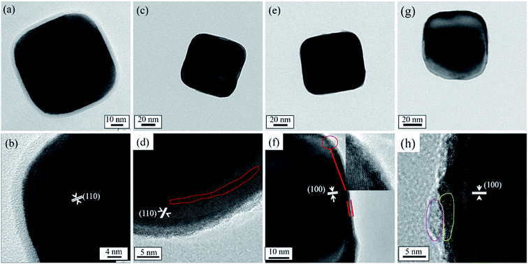 | ||
| Fig. 3 TEM and HRTEM images of BaTiO3 powders: (a) and (b) uncoated powers; (c) and (d) coated powders of 1–5; (e) and (f) coated powders of 2–5; (g) and (h) coated powders of 3–5. | ||
Fig. 3(c), (e) and (g) show that there is no obvious coated layer at the surface of the particle after coating. This indicates that the coating layer is also BaTiO3 that crystallized during 2 h of calcination at 600 °C (ultrathin films of BaTiO3 start to crystallize at 500 °C (ref. 30)). Most importantly, no Ti-rich amorphous layers are observed, so no reaction can occur with Ba2+ in the sol to form BaTiO3. In addition, the coating surface does not form the Ti-rich amorphous layer, probably because Ba ions are less likely to leach out of the surface area in the alkaline coating suspension. Furthermore, the amorphous layer is detrimental to the densification of the ceramic by the CSP. The disappearance of the amorphous layer could explain the higher densities obtained for the ceramics when using the coated powders than when using the uncoated powders. In addition, the surface coating with the ultrathin layer of several nanometers usually has high reactivity with the aqueous solution and in the sintering process. No amorphous layer with high reactivity can enhance the dissolution-precipitation process, and the BaTiO3 surfaces can easily decompose and dissolve in the liquid phase, which plays an important role in raising the ceramic density when using the coated powder.
The HRTEM image [Fig. 3(d)] shows that the surface of the coated powders of 1–5 have various distinct defects. The defect concentration decreases at the particle surface as the Ba source increases, which indicates that the defects are Ba vacancies. In addition, Ba deficiency occurs because Ba is more soluble than Ti during precipitation.29 A 2 nm crystalline layer forms at the surface of powder 2–5 and is indexed to BaTiO3, as shown in Fig. 3(f). Upon increasing the Ba source in the precursor solution, an inhomogeneous layer with a crystalline part and an amorphous part appears at the surface of powder 3–5 [Fig. 3(h)]. The composition of the amorphous phase at the surface of powder 3–5 is hard to determine because EDS or mapping cannot analyze such a small area.
Fig. 4 compares the microstructures of the as-cold-sintered ceramics made using the uncoated powders and coated powders. Fig. 4(a) and the higher-resolution Fig. 4(b) show that, in the as-cold-sintered ceramics made using uncoated powder, most of the particles are rectangle shaped and do not closely connect with each other. Particles made from the coated powder 1–5 have a deformation that facilitates close packing in the ceramic and thereby enhances the density of the ceramic [Fig. 4(c) and (d)]. The deformation of the particle confirms the speculation based on the TEM analysis that, after coating, the BaTiO3 surface easily decomposes and dissolves in the liquid phase. The other ceramics made from the coated powders 2–5 and 3–5 lead to a similar situation (data not shown).
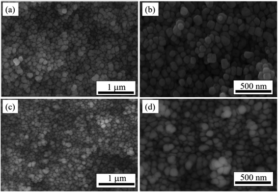 | ||
| Fig. 4 SEM images of BaTiO3 ceramics produced by (a) and (b) uncoated powders; (c) and (d) coated powders of 1–5. | ||
We used XPS technology to further investigate the chemical composition and bonding at the particle surface of the uncoated and the coated powders 1–5, 2–5, and 3–5. Fig. 5–8 shows the high-resolution spectra of individual elements Ba3d, Ti2p, O1s, and C1s, respectively. Fig. 5(a)–(d) show the Ba 3d photoelectron spectra of the BaTiO3 powders and the coated powders 1–5, 2–5, and 3–5, respectively. The Ba3d spectrum consists of two peaks, one at 778.82 eV and one at 794.12 eV, which are identified with the Ba–O bond, whereas the two subpeaks Ba3d5/2 (777.93 eV) and Ba3d3/2 (793.15 eV) are identified with BaCO3 and/or the relaxed Ba phase and are probably caused by oxygen vacancies and other residual defects.31,32
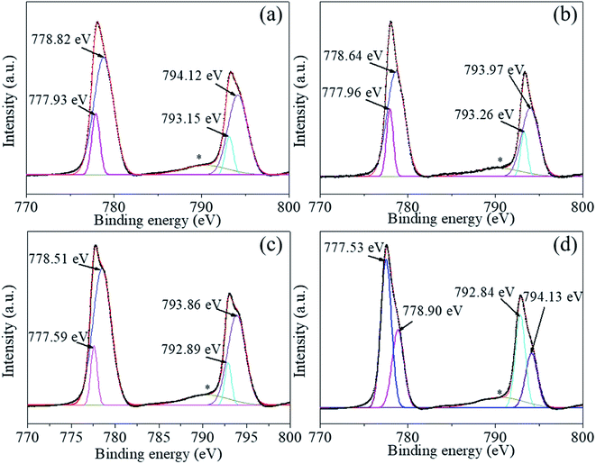 | ||
| Fig. 5 (a)–(d) Ba 3d photoelectron spectra of BaTiO3 powders and coated powders of 1–5, 2–5, and 3–5, respectively. | ||
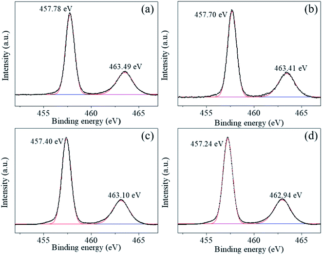 | ||
| Fig. 6 (a)–(d) Ti 2p photoelectron spectra of BaTiO3 powders and coated powders of 1–5, 2–5, and 3–5, respectively. | ||
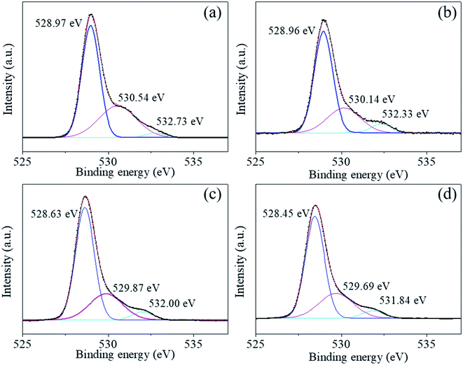 | ||
| Fig. 7 (a)–(d) O 1s photoelectron spectra of BaTiO3 powders and coated powders of 1–5, 2–5, and 3–5, respectively. | ||
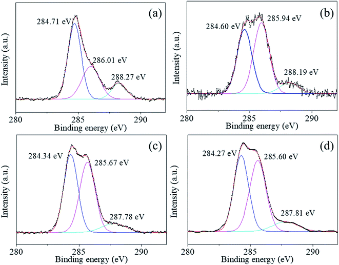 | ||
| Fig. 8 (a)–(d) C 1s photoelectron spectra of BaTiO3 powders and coated powders of 1–5, 2–5, and 3–5, respectively. | ||
The Ti2p peaks shown in Fig. 6(a)–(d) can be resolved into two components (Ti2p3/2 at 457.78 eV and Ti2p1/2 at 463.49 eV), which correspond to Ti4+ in BaTiO3.33,34 The O1s [shown in Fig. 7(a)–(d)] peak contains three components around 528.97, 530.54, and 532.73 eV, which are assigned to oxygen in BaTiO3, CO32− ions, and C–O groups, respectively.35,36 The C1s peak also contains three contributions: the first peak at 284.71 eV corresponds to the C–C and C–H groups, and the second and third peaks at 288.27 and 286.01 eV correspond to CO32− ions and C–O groups, respectively,35 in accordance with the assignment of the O1s peak [see Fig. 8(a)–(d)].
The XPS analysis shows that a small amount of BaCO3 is not detected by XRD and that the local oxygen vacancies in the synthesized material create structural defects in the sample. XPS analysis is a useful technique to detect the surface chemical composition and material structure. After coating, neither the chemical composition nor the bonding at the particle surface change significantly (Fig. 5–8), indicating that the coating layers are BaTiO3, which is consistent with the TEM results. Furthermore, comparing the C1s peaks in Fig. 8 of the uncoated and coated powders shows that the peak of C–O groups increases significantly. This is probably due to calcination, which reportedly increases surface contamination by the C–O group.35 The uncoated BaTiO3 powders calcined at 600 °C for 2 h also show a higher peak for the C–O group (Fig. S2, ESI†), but that does not help increase the density of the ceramic. Moreover, Table 2 gives the element content on the surface of the uncoated and coated powders. The ratio Ba/Ti < 1, which is common in BaTiO3 nanopowders and is caused by Ba ions leaching out of the surface area.12 After coating, the coating surface has a much lower ratio Ba/Ti by using the sol with Ba![[thin space (1/6-em)]](https://www.rsc.org/images/entities/char_2009.gif) :
:![[thin space (1/6-em)]](https://www.rsc.org/images/entities/char_2009.gif) Ti = 1
Ti = 1![[thin space (1/6-em)]](https://www.rsc.org/images/entities/char_2009.gif) :
:![[thin space (1/6-em)]](https://www.rsc.org/images/entities/char_2009.gif) 1, which is consistent with the presence of Ba vacancies in HRTEM images. This result is likely due to more facile precipitation for Ti than for Ba.28 To compensate for Ba, the sol of Ba
1, which is consistent with the presence of Ba vacancies in HRTEM images. This result is likely due to more facile precipitation for Ti than for Ba.28 To compensate for Ba, the sol of Ba![[thin space (1/6-em)]](https://www.rsc.org/images/entities/char_2009.gif) :
:![[thin space (1/6-em)]](https://www.rsc.org/images/entities/char_2009.gif) Ti = 2
Ti = 2![[thin space (1/6-em)]](https://www.rsc.org/images/entities/char_2009.gif) :
:![[thin space (1/6-em)]](https://www.rsc.org/images/entities/char_2009.gif) 1 and 3
1 and 3![[thin space (1/6-em)]](https://www.rsc.org/images/entities/char_2009.gif) :
:![[thin space (1/6-em)]](https://www.rsc.org/images/entities/char_2009.gif) 1 was used during precipitation, or the Ba(OH)2 solution was added during the CSP. When using the sol of Ba
1 was used during precipitation, or the Ba(OH)2 solution was added during the CSP. When using the sol of Ba![[thin space (1/6-em)]](https://www.rsc.org/images/entities/char_2009.gif) :
:![[thin space (1/6-em)]](https://www.rsc.org/images/entities/char_2009.gif) Ti = 2
Ti = 2![[thin space (1/6-em)]](https://www.rsc.org/images/entities/char_2009.gif) :
:![[thin space (1/6-em)]](https://www.rsc.org/images/entities/char_2009.gif) 1 and 3
1 and 3![[thin space (1/6-em)]](https://www.rsc.org/images/entities/char_2009.gif) :
:![[thin space (1/6-em)]](https://www.rsc.org/images/entities/char_2009.gif) 1, the ratio Ba/Ti increases, but still remains below 1.
1, the ratio Ba/Ti increases, but still remains below 1.
| Element | Ba | Ti | O | C |
|---|---|---|---|---|
| Uncoated | 13.86 | 16.98 | 47.19 | 21.97 |
| 1–5 | 9.65 | 19.72 | 50.84 | 19.79 |
| 2–5 | 12.23 | 19.83 | 51.14 | 16.8 |
| 3–5 | 12.6 | 19.53 | 50.79 | 17.09 |
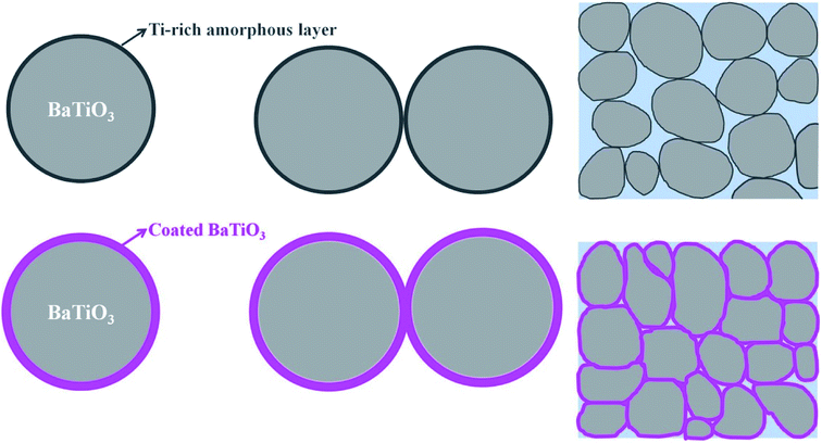
Based on these results, we propose a formation mechanism for the surface coating and the effect on the CSP. Fig. 9 shows a schematic diagram that depicts the mechanism. Uncoated BaTiO3 nanoparticles have a Ti-rich amorphous layer. The amorphous layer, which is hard to dissolve in the liquid phase, hinders the dissolution-precipitation process during the CSP. In this case, the density of the BaTiO3 ceramic is not high. When the BaTiO3 nanoparticles are coated by the BaTiO3 sol, the Ti-rich amorphous layer disappears and an ultrathin layer of BaTiO3 forms after calcination at 600 °C. The ultrathin layer can easily decompose and dissolve in the liquid phase, which enhances the dissolution-precipitation process during the CSP. The BaTiO3-coated nanoparticles promote close packing in the ceramic and thus enhance the density of the ceramic.
In order to uncover the effect of surface coating on BaTiO3 ceramics, the subsequent dielectric measurements were performed and the results are displayed in Fig. S3 (ESI†). As the Ba/Ti ratio of the cladding layer changes, it can be concluded from the frequency-dependent dielectric constant (S3–5 > S2–5 > S1–5) and dielectric loss (S3–5 < S2–5 < S1–5) that the dielectric performance of S3–5 is better than S1–5 and S2–5. We use the coated powders of 3–5 with a relatively high ratio Ba/Ti to discuss the dielectric properties of the as-cold-sintered ceramics. Fig. 10 compares the permittivity loss as a function of temperature for ceramics processed under different conditions. Fig. 10(a) and (b) show the dielectric properties of the ceramics with added water or Ba(OH)2 solution, respectively. The results show that, at room temperature, the ceramic with added Ba(OH)2 solution has higher relative dielectric permittivity than the ceramic with added water (∼185 vs. ∼127 at 1 kHz). The enhanced dielectric permittivity is caused by the compensation of Ba upon adding Ba(OH)2 solution, which reduces the Ba vacancies. In addition, a wide-ranging diffuse dielectric anomaly appears in both ceramics because the coated powders remain a part of the tetragonal phase. The as-cold-sintered ceramics were post-annealed at 700 and 900 °C, and the relative dielectric permittivity increases. As shown in Fig. 10(c) and (d), the dielectric constant increases from ∼185 to ∼810 at room temperature (1 kHz) after annealing at 700 °C, and then rises to ∼1550 if further annealed at 900 °C. This indicates that the post-annealing process further promotes the evolution of the crystal phase. Moreover, the dielectric abnormality appears clearly at ∼120 °C, which is the Curie-transition temperature of BaTiO3. The partly developed tetragonal phase of the ceramics after post-annealing thus leads to the diffuse nature of this dielectric anomaly.
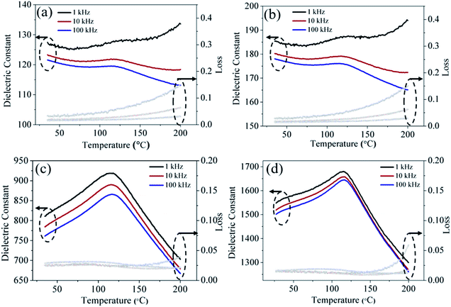 | ||
| Fig. 10 Dielectric properties as a function of temperature for ceramic of (a) W3–5, (b) S3–5, and for ceramic of S3–5 subsequently annealed at (c) 700 °C, (d) 900 °C. | ||
4. Conclusions
A surface coating method which could enhance the relative densities was used to modify the CSP for BaTiO3 ceramics. No Ti-rich amorphous layer forms on the surface of the coated powder, which had high activity. This facilitates the dissolution-precipitation process during the CSP and greatly enhances the ceramic density. Ba vacancies exist at the surface of the coated powders, so Ba(OH)2 solution was used to compensate Ba ions in the as-cold-sintered ceramics. The dielectric permittivity increased after compensation of the Ba ions. Post-annealing at 700 and 900 °C increases the relative density to 97%, and the resulting relative dielectric permittivities are 810 and 1550, respectively, at room temperature and 1 kHz.Conflicts of interest
There are no conflicts to declare.Acknowledgements
This work was supported by the State Key Laboratory of Intense Pulsed Radiation Simulation and Effect (No. SKLIPR1816), the Opening Project of Science and Technology on Reliability Physics and Application Technology of Electronic Component Laboratory, and Key Laboratory of Wide Band-gap Semiconductor Materials.References
- M. N. Rahaman, Ceramic processing and sintering, CRC Press, 2003 Search PubMed.
- P. B. Vandiver, O. Soffer, B. Klima and J. Svoboda, Science, 1989, 246, 1002–1008 CrossRef CAS PubMed.
- J. Cho, Q. Li, H. Wang, Z. Fan, J. Li, S. Xue, K. S. N. Vikrant, H. Wang, T. B. Holland, A. K. Mukherjee, R. E. García and X. Zhang, Nat. Commun., 2018, 9, 1–9 CrossRef PubMed.
- H. Z. Guo, A. L. Baker, J. Guo and C. A. Randall, J. Am. Ceram. Soc., 2016, 99, 3489–3507 CrossRef CAS.
- Y. Liu, Y. Zhang, S. Ortega, M. Ibáñez, K. H. Lim, A. Grau-Carbonell, S. Martí-Sánchez, K. M. Ng, J. Arbiol, M. V. Kovalenko, D. Cadavid and A. Cabot, Nano Lett., 2018, 18, 2557–2563 CrossRef CAS PubMed.
- J. C. Fariñas, R. Moreno, A. Pérez, M. A. García, M. García-Hernández, M. D. Salvador and A. Borrell, J. Eur. Ceram. Soc., 2018, 38, 2360–2368 CrossRef.
- M. Sokol, B. Ratzker, S. Kalabukhov, M. P. Dariel, E. Galun and N. Frage, Adv. Mater., 2018, 30, 1706283 CrossRef PubMed.
- X. Su, G. Bai, J. Zhang, J. Zhou and Y. Jia, Appl. Surf. Sci., 2018, 442, 12–19 CrossRef CAS.
- M. Sokol, M. Halabi, S. Kalabukhov and N. Frage, J. Eur. Ceram. Soc., 2017, 37, 755–762 CrossRef CAS.
- S. Funahashi, J. Guo, H. Z. Guo, K. Wang, A. L. Baker, K. Shiratsuyu and C. A. Randall, J. Am. Ceram. Soc., 2017, 100, 546–553 CrossRef CAS.
- H. Z. Guo, J. Guo, A. L. Baker and C. A. Randall, J. Am. Ceram. Soc., 2017, 100, 491–495 CrossRef CAS.
- H. Z. Guo, J. Guo, A. L. Baker and C. A. Randall, ACS Appl. Mater. Interfaces, 2016, 8, 20909–20915 CrossRef CAS PubMed.
- J. Guo, H. Z. Guo, A. L. Baker, M. T. Lanagan, E. R. Kupp, G. L. Messing and C. A. Randall, Angew. Chem., Int. Ed., 2016, 55, 11457–11461 CrossRef CAS PubMed.
- H. Z. Guo, T. J. M. Bayer, J. Guo, A. L. Baker and C. A. Randall, J. Eur. Ceram. Soc., 2017, 37, 2303–2308 CrossRef CAS.
- D. X. Wang, H. Z. Guo, C. S. Morandi, C. A. Randall and S. Trolier-McKinstry, APL Mater., 2018, 6, 016101 CrossRef.
- R. Boston, J. Guo, S. Funahashi, A. L. Baker, I. M. Reaney and C. A. Randall, RSC Adv., 2018, 8, 20372–20378 RSC.
- S. S. Faouri, A. Mostaed, J. S. Dean, D. W. Wang, D. C. Sinclair, S. Y. Zhang, W. G. Whittow, Y. Vardaxoglou and I. M. Reaney, Acta Mater., 2019, 166, 202–207 CrossRef CAS.
- D. W. Wang, D. Zhou, S. Y. Zhang, Y. Vardaxoglou, W. G. Whittow, D. Cadman and I. M. Reaney, ACS Sustainable Chem. Eng., 2018, 6, 2438–2444 CrossRef CAS.
- W. B. Hong, L. Li, H. Yan and X. M. Chen, J. Am. Ceram. Soc., 2019, 102, 5934–5940 CrossRef CAS.
- D. W. Wang, S. Y. Zhang, D. Zhou, K. X. Song, A. Feteira, Y. Vardaxoglou, W. Whittow, D. Cadman and I. M. Reaney, Materials, 2019, 12, 1370 CrossRef CAS PubMed.
- D. W. Wang, B. Siame, S. Y. Zhang, G. Wang, X. S. Ju, J. L. Li, Z. L. Lu, Y. Vardaxoglou, W. Whittow, D. Cadman, S. K. Sun, D. Zhou, K. X. Song and I. M. Reaney, J. Eur. Ceram. Soc., 2020, 40, 4029–4034 CrossRef CAS.
- D. W. Wang, D. Zhou, K. X. Song, A. Feteira, C. A. Randall and I. M. Reaney, Adv. Electron. Mater., 2019, 5, 1900025 CrossRef.
- Y. P. Ji, K. X. Song, X. J. Luo, B. Liu, H. B. Bafrooei and D. W. Wang, Frontiers in Materials, 2019, 6, 256 CrossRef.
- D. W. Wang, S. Y. Zhang, G. Wang, Y. Vardaxoglou, W. Whittow, D. Cadman, D. Zhou, K. X. Song and I. M. Reaney, Appl. Mater. Today, 2020, 18, 100519 CrossRef.
- J. P. Ma, X. M. Chen, W. Q. Ouyang, J. Wang, H. Li and J. L. Fang, Ceram. Int., 2018, 44, 4436–4441 CrossRef CAS.
- Ľ. Scholtz, P. Šutta, P. Calta, P. Novák, M. Solanská and J. Müllerová, Appl. Surf. Sci., 2018, 461, 249–254 CrossRef.
- H. Lee, H. Jeon, S. Gong, M. Ryou and Y. M. Lee, Appl. Surf. Sci., 2018, 427, 139–146 CrossRef CAS.
- S. Yoon, S. Baik, M. G. Kim and N. Shin, J. Am. Ceram. Soc., 2006, 89, 1816–1821 CrossRef CAS.
- T. J. Yosenick, Synthesis and colloidal properties of anisotropic hydrothermal barium titanate, Doctor of Philosophy, The Pennsylvania State University, Pennsylvania, 2005 Search PubMed.
- L. Qiao and X. Bi, J. Eur. Ceram. Soc., 2009, 29, 1995–2001 CrossRef CAS.
- S. Kumar, V. S. Raju and T. R. N. Kutty, Appl. Surf. Sci., 2003, 206, 250–261 CrossRef CAS.
- F. Ding, H. Gu, T. Zhang, H. Wang, F. Qu, Q. Qiu, S. Dai, X. Peng and J. Cao, Appl. Surf. Sci., 2014, 314, 622–627 CrossRef CAS.
- S. Nayak, B. Sahoo, T. K. Chaki and D. Khastgir, RSC Adv., 2014, 4, 1212–1224 RSC.
- Y. Fan, S. Yu, R. Sun, L. Li, Y. Yin, K. Wong and R. Du, Appl. Surf. Sci., 2010, 256, 6531–6535 CrossRef CAS.
- T. Chen, J. Meng, S. Wu, J. Pei, Q. Lin, X. Wei, J. Li and Z. Zhang, J. Alloys Compd., 2018, 754, 184–189 CrossRef CAS.
- F. Gheorghiu, M. Simenas, C. E. Ciomaga, M. Airimioaei, V. Kalendra, J. Banys, M. Dobromir, S. Tascu and L. Mitoseriu, Ceram. Int., 2017, 43, 9998–10005 CrossRef CAS.
Footnote |
| † Electronic supplementary information (ESI) available. See DOI: 10.1039/d0ra03849k |
| This journal is © The Royal Society of Chemistry 2020 |

