DOI:
10.1039/D0RA04320F
(Paper)
RSC Adv., 2020,
10, 44933-44945
Electrochemical performance of porous Ni-alloy electrodes for hydrogen evolution reaction from seawater electrolysis
Received
14th May 2020
, Accepted 16th November 2020
First published on 21st December 2020
Abstract
The hydrogen evolution reaction in seawater is investigated using porous Ni–Cr–Fe, Ni–Fe–Mo, Ni–Fe–C and Ni–Ti electrodes, prepared by elemental powder reactive synthesis methods. The open porosity of the four kinds of electrode materials is 23.05%, 20.47%, 25.27%, and 29.05%, respectively. The electrochemical performance of the four kinds of electrodes has been researched by polarization measurement, cyclic voltammetry and electrochemical impedance spectroscopy. The preliminary results demonstrate that the porous Ni–Cr–Fe electrode has superior catalytic activity and relatively good long-term stability for hydrogen evolution reaction in seawater. The high efficiency and reasonable stability of the porous Ni–Cr–Fe electrode catalyst demonstrate its promising applications in the rising hydrogen revolution.
1. Introduction
Hydrogen energy has attracted considerable attention because of its advantages in clean, zero emission, and gigantic storage among various renewable resources.1–4 The annual production of hydrogen is about 45 million metric tons and its consumption increases by 6% per year and hydrogen has already been introduced into the consumer sector at present.5,6 Water electrolysis has been regarded as one of the most attractive ways for hydrogen generation, due to its advantages in producing high-purity hydrogen gas, the maturity of industrialization, no pollution,7–13 etc. In order to realize efficient hydrogen evolution, acids or alkalis are always added into pure water to increase ionic conductivity.14 However, ∼75% of the earth is covered by ocean; therefore, one of the most feasible ways of realizing hydrogen evolution is to catalyze seawater due to the high electrical conductivity of seawater (33.9 mS cm−1 at 25 °C) and neutral condition.15 If the water electrolysis technology can be applied to seawater, a broad prospect will be developed. It will be easier to transform the peak electric energy into hydrogen energy, and provide hydrogen fuel vehicles and relevant medical units and enterprises with strong demand for high purity hydrogen for use.16 And it will be a good solution to the energy problem in the environment of abundant seawater resources and relatively insufficient freshwater resources.17
To achieve a high energy efficiency of water electrolysis for hydrogen production, it requires the use of an optimal catalyst to minimize the overpotential necessary to drive the hydrogen evolution reaction (HER), which means that the stable and cheap electrocatalysts with excellent catalytic activity and good corrosion resistance must be developed. Ma Y. Y. et al. have demonstrated that a cobalt molybdenum phosphide nanocrystal coated by a few-layer N-doped carbon shell (CoMoP@C) is an excellent substitute for the HER and it exhibits stable HER performance with a high Faradaic efficiency of 92.5%.18 According to the theory of electrocatalysis19 and the volcano plots, metallic nickel (Ni) shows better catalytic performances in comparison with other transition metals. Also, the alloying of two (or more) metals has long appeared as the most straightforward approach to achieve electrocatalytic activity for the HER, such as Ni–S, Ni–Al, Ni–Mo, Ni–Fe, Ni–Mo–Fe, etc20–24. For example, Ni–Fe–C cathode prepared by cathode electrodeposits method has a hydrogen overpotential of 65 mV in the 3.5 wt% NaCl of 90 °C at pH 12;25 Mg–Ni alloy showed the fastest hydrogen generation rate (23.8 mL min−1 g−1) that is 1300 times faster than that (0.017 mL min−1 g−1) of pure Mg;26 Ti/NiM (M = Co, Cu, Mo, Au, Pt) electrodes prepared by electrodepositing NiM alloys on etched Ti foil show relatively good long-term stability at −1.0 V vs. RHE over 10 h.27
Based on prior works, Ni–Fe is one of the most attractive catalysts in HER by seawater electrolysis.25 The addition of Cr element improves the material's corrosion resistance significantly.28 Our team has studied porous Ni–Cr–Fe cathode which shows significant catalytic performance in 6 M KOH solution, the Tafel slope is −130 mV dec−1, and the exchange current density is 7 × 10⁻⁴ A cm−2 at elevated temperature.29 It is also found that Ni–Fe–C cathode owns benefit of good catalytic activity and stability for HER, and the observed activity is mainly due to the intrinsic activity induced by carbon embedded into Ni–Fe matrix.30–33 In addition, various authors have demonstrated that titanium and its alloys are widely used in the aerospace, automotive, chemical, and biomedical industries owing to their excellent corrosion resistance, bio-compatibility, high specific strength, and low density.34–36 Therefore, there is extensive research on the facile syntheses of hierarchically porous Ni-based composites for electrochemical hydrogen production as well as other energy conversion and storage, which are calcined from MOF-derived transition metal based materials.37–40 In order to increase real activity area of cathode materials and enhance HER activity, porous alloys which possess interconnected pores are used to promote the hydrogen bubble separation from electrode surface.
In this work, four different kinds of porous Ni-alloy electrodes—Ni–Cr–Fe, Ni–Fe–Mo, Ni–Fe–C and Ni–Ti—have been fabricated by elemental powder reactive synthesis methods. The aim of the present work is to study the electrocatalytic performance, stability and corrosion resistance of the developed electrodes for HER in seawater.
2. Experimental
2.1 Preparation of porous Ni-alloy electrodes
Commercially pure powders were mixed respectively according to Table 1. These powders were dry-mixed in a tumbler ball mill for 10 h, followed by cold pressing into compact with a dimension of 7 mm × 25 mm × 2 mm under a pressure of 90 MPa. The specimens were then sintered respectively at temperatures of 850 °C, 800 °C, 1100 °C and 1100 °C in a vacuum furnace under 1 × 10⁻³ Pa, as seen from Table 1. Porous Ni–Cr–Fe electrodes with sintering temperature of 1000 °C, 1100 °C and 1150 °C were also prepared for comparing the HER activities. The four kinds of as-obtained porous materials were examined by X-ray diffraction (XRD) to identify the phase composition and corresponding crystalline structures. Back scattered electron diffraction (BSED) and energy dispersive X-ray spectroscope (EDS) were used to observe the microstructure and analyze the components of the four kinds of porous electrode materials after sintering process.
Table 1 Main preparation parameters of the four kinds of electrodes
| Porous electrode |
Powder particle size |
Ratio (in weight) |
Sintering temperature (°C) |
| Ni–Cr–Fe |
Ni, Cr, Fe (3–5 μm) |
7![[thin space (1/6-em)]](https://www.rsc.org/images/entities/char_2009.gif) : :![[thin space (1/6-em)]](https://www.rsc.org/images/entities/char_2009.gif) 2 2![[thin space (1/6-em)]](https://www.rsc.org/images/entities/char_2009.gif) : :![[thin space (1/6-em)]](https://www.rsc.org/images/entities/char_2009.gif) 1 1 |
850 |
| Ni–Fe–Mo |
Ni, Fe, Mo (3–5 μm) |
8![[thin space (1/6-em)]](https://www.rsc.org/images/entities/char_2009.gif) : :![[thin space (1/6-em)]](https://www.rsc.org/images/entities/char_2009.gif) 1 1![[thin space (1/6-em)]](https://www.rsc.org/images/entities/char_2009.gif) : :![[thin space (1/6-em)]](https://www.rsc.org/images/entities/char_2009.gif) 1 1 |
800 |
| Ni–Fe–C |
Ni, Fe (3–5 μm); C (∼38.5 μm) |
7![[thin space (1/6-em)]](https://www.rsc.org/images/entities/char_2009.gif) : :![[thin space (1/6-em)]](https://www.rsc.org/images/entities/char_2009.gif) 2 2![[thin space (1/6-em)]](https://www.rsc.org/images/entities/char_2009.gif) : :![[thin space (1/6-em)]](https://www.rsc.org/images/entities/char_2009.gif) 1 1 |
1100 |
| Ni–Ti |
Ni, Ti (3–5 μm) |
7![[thin space (1/6-em)]](https://www.rsc.org/images/entities/char_2009.gif) : :![[thin space (1/6-em)]](https://www.rsc.org/images/entities/char_2009.gif) 3 3 |
1100 |
2.2 Characterization of porous Ni-alloy electrodes
In order to examine the surface microstructure and composition of the prepared samples, a field-emission scanning electron microscope (Nova NanoSEM 230, FEI Co., Hillsboro, OR, USA) and X-ray diffractometer (Rigaku Corp., Kyoto, Japan) were used in research. The open porosity of the porous materials was determined according to Archimedes' method.
All the electrochemical tests were carried out using a CS350 electrochemical workstation in a standard three-electrode electrochemical cell at room temperature (298 K) in artificial seawater solution. The artificial seawater was prepared by the following composition: 26.726 g L−1 NaCl, 2.260 g L−1 MgCl2, 3.248 g L−1 MgSO4, 1.153 g L−1 CaCl2, 0.198 g L−1 NaHCO3, 0.721 g L−1 KCl. We dissolved these composition in distilled water and stirred evenly to obtain the artificial seawater. Pt foil and saturated calomel electrode (SCE) were used as the counter and reference electrodes, respectively. The latter was connected to the working electrode via a Luggin capillary positioned close to the working electrode. Before electrochemical testing, the prepared electrodes were sealed by silicone rubber, only leaving 1 cm2 of the total area of the working electrodes exposed to the seawater electrolyte. The electrochemical characterizations of the prepared specimens were measured by cyclic voltammetry (CV), cathodic polarization and electrochemical impedance spectroscopy (EIS) techniques. Each electrochemical experiment was repeated three times with a fresh specimen for each test. The linear sweep cathodic polarization curves were measured by scanning a potential from −0.01 V to −2.2 V (versus the open circuit potential), at the scan rate of 1 mV s−1. The CV curves were recorded at scan rates ranging from 1 to 40 mV s−1. Prior to each measurement the working electrodes were conditioned at −1.2 V vs. SCE for 30 min to reduce oxide film on the electrode surface. EIS experiments were conducted in the frequency range of 100 kHz to 0.01 Hz for the HER by applying alternating current signal of 10 mV peak to peak.
3. Results and discussion
3.1 Morphology characterization of porous Ni-alloy electrodes
The morphology of the prepared electrodes is shown in Fig. 1. All electrodes are interconnected and show similar and irregular shaped pores with high porosity. Moreover, there are some small pores existing in the walls of the bigger pores, as manifested by the interconnection between these pores; thus, the inner walls of the pores are generally unsmooth. All surfaces exhibit a rough surface which contributes to provide more active sites for HER. It is generally believed that increasing the surface area is one method to enhance the activity of cathode materials. Their pore structure parameters are shown in Table 2. These four kinds of electrodes have a similar porosity.
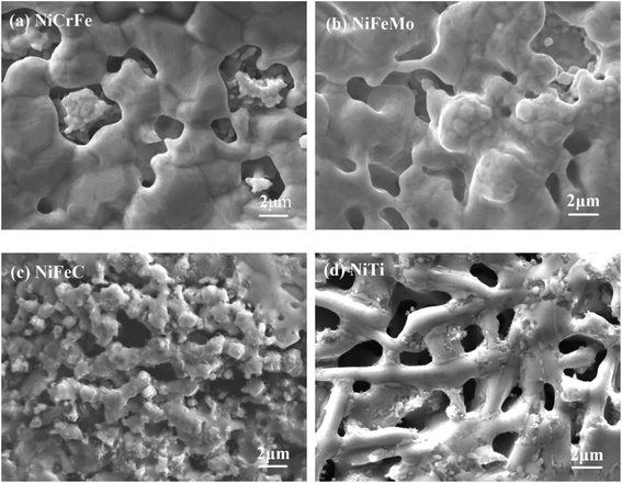 |
| | Fig. 1 SEM morphology of porous (a) Ni–Cr–Fe, (b) Ni–Fe–Mo, (c) Ni–Fe–C, (d) Ni–Ti electrode. | |
Table 2 Pore structure parameters of the prepared four kinds of electrodes
| Porous electrode |
Porosity (%) |
| Ni–Cr–Fe |
23.05 |
| Ni–Fe–Mo |
20.47 |
| Ni–Fe–C |
25.27 |
| Ni–Ti |
29.05 |
3.2 Microstructure analyses of porous Ni-alloy electrodes
The phase composition and crystalline structure were characterized by XRD. Fig. 2 shows the comparison of the XRD patterns of the four different electrodes. The patterns indicate that the prepared four kinds of materials have a very similar crystal structure, the main diffraction peaks are (111), (200) and (220) due to the face centered cubic (fcc) phase presented on the electrodes. A wide peak at 2θ = 44.5° is appeared in all curves, which suggests that all the electrodes have amorphous structure. The amorphous structure is found to expose more active sites due to their unsaturated sites on the surface.41 As shown in Fig. 2, porous Ni–Cr–Fe electrode consists of the solid solution phase of (Ni, Cr, Fe) only. As for porous Ni–Fe–Mo electrode, the solid solution phase of (Ni, Fe, Mo) and NiMo compound are mainly formed, along with a small part of NiFe and FeMo compounds. As for porous Ni–Fe–C electrode, the peaks correspond to characteristic peaks of taenite iron-nickel, and the diffraction peaks of C can also be observed. As for porous Ni–Ti electrode, there are no elemental Ti and Ni detectable on the electrode. NiTi appears as the main phase, Ti2Ni and TiNi3 are also detected.
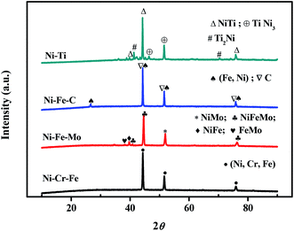 |
| | Fig. 2 XRD patterns of porous Ni–Cr–Fe, Ni–Fe–Mo, Ni–Fe–C and Ni–Ti electrodes. | |
According to the results of BSED and EDS, as for porous Ni–Cr–Fe, a large part of Fig. 3a shows the dark gray matrix of (Ni, Cr, Fe) solid solution and rest part shows the light gray phase of solid solution containing NiCr and NiFe compound. The results indicate that uniform and stable solid solution phases are mainly formed in porous Ni–Cr–Fe alloy. In Fig. 3b, most of the areas are gray, the EDS results show that they are the matrix phase of NiFeMo solid solution with a small amount of Mo element; the white area is the agglomerate of Mo element with a small amount of Ni and Fe elements; the light gray area is the solid solution phase with a small amount of NiMo and NiFe compounds; the dark gray area next to the pores is mainly the NiFe compound phase. The BSED pattern of porous Ni–Fe–C alloy in Fig. 3c is uniform and composed of the diffusion of Ni3Fe and C. In Fig. 3d, for porous Ni–Ti alloy, the light gray area is NiTi austenitic phase with a small amount of Ni3Ti phase, while the dark gray area is NiTi austenitic phase with a small amount of NiTi2 phase.
 |
| | Fig. 3 BSED and EDS results of porous (a) Ni–Cr–Fe; (b) Ni–Fe–Mo; (c) Ni–Fe–C; (d) Ni–Ti electrodes. | |
3.3 Electrocatalytic activity of porous Ni-alloy electrodes
The electrocatalytic activity of the four specimens as electrodes for HER in seawater solution is investigated for comparison. Cyclic voltammetry (CV) was employed to measure the double layer capacity of the electrodes and typical CV recorded at different scan rates is displayed in Fig. 4a–d. In the regions shown in Fig. 4a–d, the average value of capacitive current is proportional to the double layer capacitance, and the average value of double layer current densities jdl,ave with scan rate is described as following:42| | |
jdl,ave = (|jc| + |ja|)/2 = Cdl(dE/dt)
| (1) |
where Cdl is the double layer capacitance of electrode, and jc and ja are cathodic and anodic current density, respectively. Curves of current density against scan rate for all the four kinds of studied electrodes show a good linear relationship, as presented in Fig. 4e. Therefore, the capacitances of four electrodes can be estimated from the slopes. The relative magnitude of the roughness factor, Rf, which represents the real surface of the electrode,42,43 is calculated by assuming the value of 20 mF cm−2 for the capacitance of smooth mercury electrode, and the results are summarized in Table 3. The results indicate that both the capacitance order and roughness factor order are: porous Ni–Ti > porous Ni–Fe–C > porous Ni–Cr–Fe > porous Ni–Fe–Mo, indicating that porous Ni–Cr–Fe has the relatively smaller surface area.
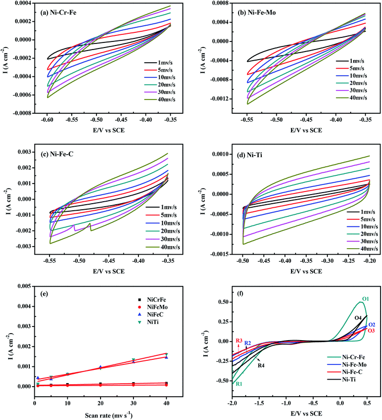 |
| | Fig. 4 (a–d) Cyclic voltammograms in the double layer region of porous Ni-alloy electrodes at scan rates ranging from 1 to 40 mV s−1: (a) Ni–Cr–Fe; (b) Ni–Fe–Mo; (c) Ni–Fe–C; (d) Ni–Ti. (e) Mean current density as a function of scan rate for the electrodes. (f) Cyclic voltammograms of the four kinds of electrodes in the scan range −2.0 V to 0.5 V at 298 K. | |
Table 3 Capacitance and surface roughness of the porous electrocatalysts
| Porous electrode |
Cdl (μF cm−2) |
Rf |
| Ni–Cr–Fe |
3058.04 |
152.902 |
| Ni–Fe–Mo |
994.937 |
49.747 |
| Ni–Fe–C |
28![[thin space (1/6-em)]](https://www.rsc.org/images/entities/char_2009.gif) 587.9 587.9 |
1429.395 |
| Ni–Ti |
35![[thin space (1/6-em)]](https://www.rsc.org/images/entities/char_2009.gif) 976 976 |
1798.8 |
Fig. 4f shows the cyclic voltammograms of the four kinds of electrodes with a scan rate of 5 mV s−1 at ambient temperature in seawater solution. As shown in Fig. 4f, the shapes of the CV curves for the four kinds of electrodes are similar with each other. The reduction peaks of hydrogen evolution include R1, R2, R3 and R4. The oxidation peaks O1, O2, O3 and O4 are corresponding to the hydrogen desorption reaction. The intensity of the hydrogen desorption peak of the porous electrodes is in direct proportion to that of the hydrogen evolution reaction. Among these four kinds of electrodes, the HER peaks of porous Ni–Cr–Fe electrode (R1) show much higher intensities at respective overpotentials.
In neutral solution, Ni alloys behave like an electropositive metal because the anodic process is the oxidation of nickel to a slightly soluble hydroxide or oxide:44–46
| | |
Ni + 2OH− = α-Ni(OH)2 + 2e−
| (2) |
| | |
Ni + 2H2O = NiO + 2H+ + 2e−
| (3) |
whereas, when this passive electrode is anodized further, nickel oxyhydroxide appears:
| | |
Ni(OH)2 + OH− = NiOOH + H2O + e−
| (4) |
This electrochemical oxidation causes the release of a proton from the Ni hydroxide layer to produce H2O.47–49 Compared with the other three kinds of electrodes, the increase in the anodic peak current of porous Ni–Cr–Fe electrode renders the material with better properties. The capacity of charge can be indicated by the broad region observed in the anodic scan, i.e. the quantity of hydrogen in the cathode materials; below this region, the current rapidly increases in the negative direction. It should be noted that the anodic polarization current for the prepared cathode materials consists of two typical steps—the hydrogen charge transfer reaction across the electrode–electrolyte interface and hydrogen diffusion in the surface. Thus, our investigation indicates that the porous Ni–Cr–Fe has higher HER activity. It can be inferred that the high catalytic performance is not just because of its surface area.
The linear sweep cathodic polarization for HER in seawater is illustrated in Fig. 5. It shows that the cathodic current densities of the four electrodes increase with the increase of the overpotential. As shown in Fig. 5a, among four kinds of porous electrodes, the catalytic property of porous Ni–Cr–Fe electrode is higher than others, which only needs potential of −1.543 V to achieve current density of 100 mA cm−2. This is in accordance with the results of the cyclic voltammograms (Fig. 4f) mentioned before. Notice that although porous Ni–Ti electrode has the highest surface area among the four kinds of electrodes, the catalytic performance of Ni–Ti is much worse than that of Ni–Cr–Fe electrode. However, Fig. 5a has shown that Ni–Cr–Fe exhibit the best catalytic performance, indicating that the high electrocatalytic activity of porous Ni–Cr–Fe electrode is likely due to the high solubility of Cr and Fe atoms on the Ni matrix and the synergistic effect among them for catalysis of the HER. Moreover, porous Ni–Cr–Fe with the composition of 7![[thin space (1/6-em)]](https://www.rsc.org/images/entities/char_2009.gif) :
:![[thin space (1/6-em)]](https://www.rsc.org/images/entities/char_2009.gif) 2
2![[thin space (1/6-em)]](https://www.rsc.org/images/entities/char_2009.gif) :
:![[thin space (1/6-em)]](https://www.rsc.org/images/entities/char_2009.gif) 1 sintered under the temperature of 850 °C displays the best activity for the HER. Based on this, without special version, all the figures and tables about porous Ni–Cr–Fe electrode illustrate the performance of it under the sintering temperature of 850 °C.
1 sintered under the temperature of 850 °C displays the best activity for the HER. Based on this, without special version, all the figures and tables about porous Ni–Cr–Fe electrode illustrate the performance of it under the sintering temperature of 850 °C.
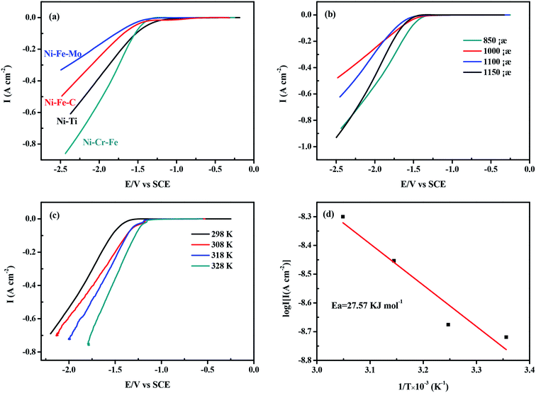 |
| | Fig. 5 (a) The cathodic linear sweep for the HER of the four kinds of porous electrodes; (b) the cathodic linear sweep for the HER on the porous Ni–Cr–Fe electrode with the same composition sintered at different temperatures; (c) the cathodic linear sweep for the HER on the porous Ni–Cr–Fe electrode at temperature range from 298 K to 328 K; (d) Arrhenius plots: semi-logarithmic dependence of exchange current density on inverse temperature for the porous Ni–Cr–Fe electrode in seawater. | |
In order to deep understand the HER mechanism of porous electrodes, the Tafel slope of the four electrodes on the linear scan curve of the lower overpotential region is used to analyze the HER process, as summarized in Table 4. It indicates that HER on all investigated electrodes can be described by Tafel equation:
| |
η = b![[thin space (1/6-em)]](https://www.rsc.org/images/entities/char_2009.gif) log log![[thin space (1/6-em)]](https://www.rsc.org/images/entities/char_2009.gif) i + a i + a
| (5) |
where
η is the potential after iR correction,
b is the Tafel slope,
i is the current density and
a is the Tafel constant. Exchange current density
i0 can be determined by
eqn (6):
| |
a = (2.3RT)/(αneF) × log![[thin space (1/6-em)]](https://www.rsc.org/images/entities/char_2009.gif) i0 i0
| (6) |
Table 4 Comparison of HER parameters for different catalytic electrodes
| Porous electrode |
−b (mV dec−1) |
i−1.7 V (mA cm−2) |
Onset potential (V vs. SCE) |
I−1.7 V/Rf (mA cm−2) |
| Ni–Cr–Fe |
201.5 |
−263.85 |
−1.33 |
1.73 |
| Ni–Fe–Mo |
283.2 |
−76.942 |
−1.28 |
0.3 |
| Ni–Fe–C |
256.3 |
−108.35 |
−1.24 |
0.07 |
| Ni–Ti |
248.5 |
−193.43 |
−1.04 |
0.26 |
The charge–transfer coefficient, α, can be obtained from the Tafel slope by using eqn (7):
where
ne represents the exchanged electrons, and
R (=8.314 J mol
−1 K
−1) and F (=96
![[thin space (1/6-em)]](https://www.rsc.org/images/entities/char_2009.gif)
485C mol
−1) are the gas and the Faraday constants, respectively. It is well established that the mechanism of the HER on a metallic electrode
M in aqueous basic solution involves the proton discharge electrosorption (Volmer reaction,
eqn (8)), electrochemical desorption (Heyrovsky reaction,
eqn (9)) and H recombination (Tafel reaction,
eqn (10)):
50| | |
M + H2O + e− → MHads + OH−
| (8) |
| | |
MHads + H2O + e− → H2 + M + OH−
| (9) |
| | |
MHads + MHads → H2 + M
| (10) |
where MH
ads represents hydrogen adsorbed on the electrode surface. As shown in
Table 4, the Tafel slopes of porous Ni–Cr–Fe, Ni–Fe–Mo, Ni–Fe–C, Ni–Ti are −201.5, −283.2, −256.3 and −248.5 mV dec
−1, respectively. Porous Ni–Cr–Fe exhibits a small Tafel slope, suggesting a higher HER activity. It is considered that a small Tafel slope is highly desirable for practical applications, because it ensures the energy efficiency and promotes hydrogen evolution with a small overpotential. As widely accepted, Tafel slopes of 120, 40 and 30 mV dec
−1 are observed for the Volmer, Heyrovsky and Tafel determining rate steps, respectively. The Tafel slope values of the four electrodes are higher than 120 mV dec
−1, suggesting that hydrogen evolution on the four electrodes is probably controlled by the Volmer mechanism (
eqn (8)) and the charge transfer reaction is regarded as the rate determinating step for HER. The Volmer reaction is a primary reaction for HER, which produces adsorbed H atoms (H
ads) on the electrode surface by the discharge of H
2O. As shown in
Table 4, at the same cathode potential (−1.7 V), the current densities value (
i−1.7 V) of HER on porous Ni–Cr–Fe electrode is higher than those on the three other electrodes. Meanwhile, porous Ni–Cr–Fe electrode is found to possess the maximum
i−1.7 V/
Rf, which means that its intrinsic catalytic activity is about 6 times higher than that of other electrodes. So the intrinsic activity of porous Ni–Cr–Fe electrode plays a leading role in the hydrogen evolution process. A general conclusion found in the literature is that the intrinsic activity for the HER is related to the electronic structure of metals. Kita
51,52 proposed that the intrinsic activity of metals for HER was related to the outer shell electronic configuration of elements in their ground state. It increased with the increase of the number of the d-electrons and reached the maximum activity for nearly filled d-orbitals.
Fig. 5c presents polarization curves obtained for the porous Ni–Cr–Fe alloy at temperatures ranging from 298 to 328 K. As shown in Fig. 5c, the polarization curves exhibit the expected behavior. The increase of temperature leads to a significant reduction of the overpotential and an increase of the exchange current density. The Tafel slopes (b) and exchange current densities (i0) at different temperatures are shown in Table 5. For a single rate-limited thermally activated process, the curve of log![[thin space (1/6-em)]](https://www.rsc.org/images/entities/char_2009.gif) i0 against T−1 exhibits a linear relationship. The apparent activation energy can be determined according to the slope of the curve. The apparent energy of activation for the porous Ni–Cr–Fe electrode has been calculated from the slope of the Arrhenius plot presented in Fig. 5d according to the following equation:53
i0 against T−1 exhibits a linear relationship. The apparent activation energy can be determined according to the slope of the curve. The apparent energy of activation for the porous Ni–Cr–Fe electrode has been calculated from the slope of the Arrhenius plot presented in Fig. 5d according to the following equation:53
| |
log![[thin space (1/6-em)]](https://www.rsc.org/images/entities/char_2009.gif) i0 = log i0 = log![[thin space (1/6-em)]](https://www.rsc.org/images/entities/i_char_2009.gif) A − Ea/2.303RT A − Ea/2.303RT
| (11) |
where
i0 is the exchange current density,
A is a pre-exponential factor,
Ea is the activation energy,
R is the gas constant and
T is the absolute temperature.
Fig. 5d reveals that the activation energy of the porous Ni–Cr–Fe electrode is 27.57 kJ mol
−1, lower than those obtained on Ni (35 kJ mol
−1), Fe (39 kJ mol
−1) and Ni–Fe (31 kJ mol
−1)
54 in alkaline solution (Because of the fewer research on hydrogen evolution from seawater electrolysis, there is almost no literature we can find about the activation energy in seawater solution, we reference the data in alkaline solution here). Apparently, porous Ni–Cr–Fe shows higher catalytic activity by reducing the activation energy of the reaction. The enhanced activity is attributed to its higher intrinsic activity.
Table 5 Kinetics parameters from the polarization curves for the porous Ni–Cr–Fe electrode, obtained at different temperature
| T (K) |
−b (mV dec−1) |
i0 (A cm−2) |
| 298 |
201.5 |
1.91 × 10⁻⁹ |
| 308 |
185.3 |
2.11 × 10⁻⁹ |
| 318 |
173.7 |
3.52 × 10⁻⁹ |
| 328 |
161.8 |
5.01 × 10⁻⁹ |
To characterize the electrocatalytic activity of porous Ni–Cr–Fe electrode, the EIS analysis is carried out at different overpotential values (η = 0, −0.1, −0.15 and −0.2 V). The impedance data obtained from the EIS tests are presented in the form of both Nyquist and Bode diagrams, the EIS data are fitted with the Armstrong equivalent circuit model, as shown in Fig. 6. In Bode spectrum (Fig. 6b), a broaden peak in high frequency (HF) range and a small peak at low frequency (LF) range could be seen, indicating the presence of two time constants. These two time constants can also be represented by the two semicircles at HF and LF range in Nyquist diagram (Fig. 6a). The EIS data are fitted according to the electrical equivalent circuit (EEC) model, which was first proposed by Armstrong and Henderson,55 as shown in Fig. 6c. This model reflects the response of HER system characterized by two time constants, the first time constant is related to the charge transfer kinetics, while the second time constant is related to the hydrogen adsorption.56–58 This is in accordance with the results mentioned before: hydrogen evolution in seawater on the porous Ni–Cr–Fe electrode is controlled by the Volmer mechanism and the charge transfer reaction is regarded as the rate determinating step for HER. As could be seen in Fig. 6a, the two time constants are overpotential-dependent, i.e. both the LF and HF semicircles decrease with increase of overpotential. In the EEC shown in Fig. 6c, each element stands for different meaning. Rs is the solution resistance. CPE1 is related to the double layer capacitance (Cdl). Rct is the charge transfer resistance. CPE2 is the constant phase element of the pseudo-capacitance (Cp), and Rp is associated with the resistance of the adsorbed intermediate Hads. The overall rate of the HER is related to both the charge transfer resistance (Rct) and hydrogen adsorption resistance (Rp).
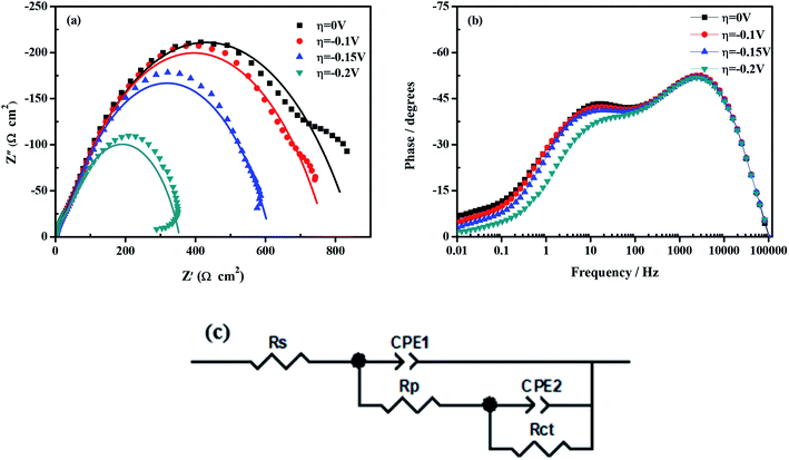 |
| | Fig. 6 Impedance data of porous Ni–Cr–Fe electrode: (a) Nyquist representation; (b) Bode representation of the phase angle as a function of frequency; (c) equivalent circuit model. | |
In conclusion, porous Ni–Cr–Fe electrode exhibits extremely electrocatalytic performance for HER in seawater compared with the other three kinds of electrodes, which can mainly be ascribed to the high solubility of Cr and Fe atoms in the Ni matrix and the higher intrinsic catalytic activity.
3.4 Electrocatalytic stability of porous Ni-alloy electrodes
Apart from the high catalytic activity, the relatively good durability of the cathode materials is also of great significance for practical applications. By recording CV curves from −1.5 to −0.9 V in seawater at 298 K for 500 cycles, the electrochemical stability is investigated and their suitability for the possible industrial application is evaluated, as shown in Fig. 7. Table 6 depicts that the porous Ni–Cr–Fe electrode possesses the smallest current decay (33.17%) after 500 cycles as compared to the cathodic current density in the first cycle in seawater. In Fig. 8, there is little difference before and after long-term measurements for porous Ni–Cr–Fe. Combined with the current decay and SEM morphology after 500 cycles. These results suggest that porous Ni–Cr–Fe electrode has higher electrochemical stability for hydrogen evolution than the other tested electrodes.
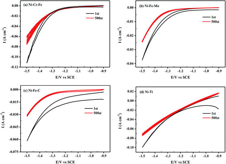 |
| | Fig. 7 Cyclic voltammograms in seawater at a scan rate of 10 mV s−1 from −1.5 to −0.9 V for the first cycle and the 500th cycle of (a) Ni–Cr–Fe; (b) Ni–Fe–Mo; (c) Ni–Fe–C; (d) Ni–Ti. | |
Table 6 The current decay after 500 cycles for HER
| Porous electrode |
i−1.5 V of 1st (mA cm−2) |
i−1.5 V of 500th (mA cm−2) |
Current decay (%) |
| Ni–Cr–Fe |
111.46 |
74.49 |
33.17 |
| Ni–Fe–Mo |
37.40 |
24.55 |
34.36 |
| Ni–Fe–C |
61.70 |
32.05 |
48.05 |
| Ni–Ti |
99.40 |
65.48 |
34.20 |
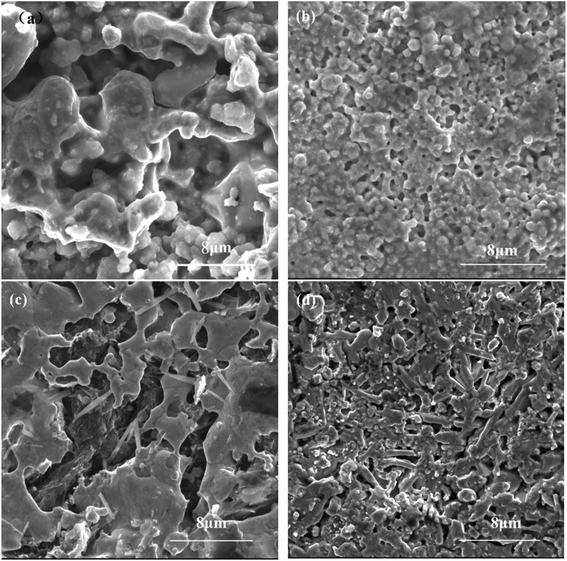 |
| | Fig. 8 SEM morphology of porous (a) Ni–Cr–Fe, (b) Ni–Fe–Mo, (c) Ni–Fe–C, (d) Ni–Ti electrode after 500 cycles. | |
3.5 Corrosion resistance of porous Ni-alloy electrodes
Fig. 9 presents the evolution of the open circuit potential as a function of time. The open circuit potentials of porous Ni–Cr–Fe, Ni–Fe–Mo, Ni–Fe–C and Ni–Ti electrodes start from a value of −0.243 V, −0.975 V, −0.388 V and −0.946 V, respectively. Then this value shifts to a noble direction before becoming stabilized, which demonstrates its good electrochemical stability. The change of the open circuit potential with time suggests the formation of passive film on the four porous electrodes in seawater solution. In this work, porous Ni–Cr–Fe electrode exhibits higher positive open circuit potential, indicating a better corrosion resistance.
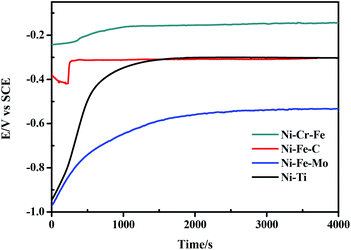 |
| | Fig. 9 Evolution of open circuit potential over time for porous Ni-alloy electrodes. | |
The Tafel polarization curves of the four electrodes measured in seawater solution are shown in Fig. 10. According to the polarization curves, it can be seen that porous Ni–Cr–Fe electrode has higher corrosion potential than the other three kinds of electrodes. Fig. 11 shows SEM morphology of the four porous electrodes after corrosion resistance. As compared with the samples before electrochemical test, the changes of the pore structure are not obvious and there is also no pit corrosion or loosen corrosion product on the surface of the porous Ni–Cr–Fe electrode. Therefore, porous Ni–Cr–Fe electrode exhibits excellent corrosion resistance in seawater solution.
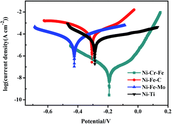 |
| | Fig. 10 Tafel polarization curves of the four kinds of porous electrodes in seawater. | |
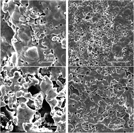 |
| | Fig. 11 SEM morphology of porous (a) Ni–Cr–Fe, (b) Ni–Fe–Mo, (c) Ni–Fe–C, (d) Ni–Ti electrode after corrosion resistance. | |
4. Conclusions
In summary, we have made a category of porous Ni-alloy (Ni–Cr–Fe, Ni–Fe–Mo, Ni–Fe–C, Ni–Ti) catalytic electrodes by elemental powder reactive synthesis method. Their catalytic performances are thoroughly studied by characterizing hydrogen evolution in real seawater solution. The preliminary results demonstrate that porous Ni–Cr–Fe electrode has higher catalytic activity, good long-term stability and corrosion resistance toward HER processes in seawater due to the high solubility of Cr and Fe atoms on the Ni matrix and the synergistic interaction among them for catalysis of the HER. The work presented here is far from optimized, but the reasonable catalytic activity, durability and low cost demonstrate that porous Ni-alloy electrodes can be potentially utilized as catalytic electrodes for high-efficiency hydrogen evolution by seawater splitting.
Conflicts of interest
There are no conflicts to declare.
Acknowledgements
The authors are grateful to the Project of the Ministry of Education of Hunan Province [grant numbers 17B250, 17A204], the Project of Science and Technology Department of Hunan Province [grant numbers 2018JJ3505, 2018GK5033] and the Project of state key laboratory of advanced welding and joining of Harbin Institute of Technology [grant number AWJ-20-M02].
References
- B. Rezaei, M. Mokhtarianpour and A. A. Ensafi, Fabricated of bimetallic Pd/Pt nanostructure deposited on copper nanofoam substrate by galvanic replacement as an effective electrocatalyst for hydrogen evolution reaction, Int. J. Hydrogen Energy, 2015, 40, 6754–6762 Search PubMed.
- D. M. Hou, W. Zhou, X. J. Liu, K. Zhou, J. Xie, G. Q. Li and S. W. Chen, Pt nanoparticles/MoS2 nanosheets/carbon fibers as efficient catalyst for the hydrogen evolution reaction, Electrochim. Acta, 2015, 166, 26–31 Search PubMed.
- H. Y. Li, Q. W. Tang, B. L. He and P. Z. Yang, Robust electrocatalysts from an alloyed Pt-Ru-M (M=Cr, Fe, Co, Ni, Mo)-decorated Ti mesh for hydrogen evolution by seawater splitting, J. Mater. Chem. A, 2016, 4, 6513–6520 Search PubMed.
- Y. Y. Zhao, Q. W. Tang, B. L. He and P. Z. Yang, Carbide decorated carbon nanotube electrocatalys for high-efficiency hydrogen evolution from seawater, RSC Adv., 2016, 6, 93267–93274 Search PubMed.
- H. R. Krishna, Review of research on production methods of hydrogen: future fuel, Eur. J. Biochem., 2013, 1, 84–93 Search PubMed.
- A. G. Vidales and S. Omanovic, Evaluation of nickel-molybdenum-oxides as cathodes for hydrogen evolution by water electrolysis in acidic, alkaline, and neutral media, Electrochim. Acta, 2018, 262, 115–123 Search PubMed.
- M. A. Wahab, Y. Jia, D. J. Yang, H. J. Zhao and X. D. Yao, Enhanced hydrogen desorption from Mg(BH4)2 by combining nanoconfinement and a Ni catalyst, J. Mater. Chem. A, 2013, 10, 3471–3478 Search PubMed.
- Y. Jia, C. H. Sun, S. H. Shen, J. Zou, S. S. Mao and X. D. Yao, Combination of nanosizing and interfacial effect: Future perspective for designing Mg-based nanomaterials for hydrogen storage, Renewable Sustainable Energy Rev., 2015, 44, 289–303 Search PubMed.
- N. Shimizu, S. Hotta, T. Sekiya and O. Oda, A novel method of hydrogen generation by water electrolysis using an ultra-short-pulse power supply, J. Appl. Electrochem., 2006, 36, 419–423 Search PubMed.
- A. Ursúa, L. Marroyo, E. Gubía and L. M. Gandía, Influence of the power supply on the energy efficiency of an alkaline water electrolyser, Int. J. Hydrogen Energy, 2009, 34, 3221–3233 Search PubMed.
- Y. Pan, Y. Q. Liu and C. G. Liu, Nanostructured nickel phosphide supported on carbon nanospheres: Synthesis and application as an efficient electrocatalyst for hydrogen evolution, J. Power Sources, 2015, 285, 169–177 Search PubMed.
- E. J. Popczun, J. R. Mckone, C. G. Read, A. J. Biacchi, A. M. Wiltrout, N. S. Lewis and R. E. Schaak, Nanostructured nickel phosphide as an electrocatalyst for the hydrogen evolution reaction, J. Am. Chem. Soc., 2013, 135, 9267–9270 Search PubMed.
- K. Y. Zhang, W. Xiao, J. Y. Li, J. G. Liu and C. W. Yan, Two-step preparation of porous nickel-sulfur electrode for hydrogen evolution in alkaline Water electrolysis, Electrochim. Acta, 2017, 228, 422–427 Search PubMed.
- J. J. Zheng, Binary platinum alloy electrodes for hydrogen and oxygen evolutions by seawater splitting, Appl. Surf. Sci., 2017, 413, 72–82 Search PubMed.
- X. M. Niu, Q. W. Tang, B. L. He and P. Z. Yang, Robust and stable ruthenium alloy electrocatalysts for hydrogen evolution by seawater splitting, Electrochim. Acta, 2016, 208, 180–187 Search PubMed.
- W. Nam, S. Oh, H. Joo, S. Sarp, J. Cho, B. W. Nam and J. Yoon, Preparation of anodized TiO2 photoanode for photoelectrochemical hydrogen production using natural seawater, Sol. Energy Mater. Sol. Cells, 2010, 94, 1809–1815 Search PubMed.
- S. Hsu, J. Miao, L. Zhang, J. Gao, H. Wang, H. Tao, S. F. Hung, A. Vasileff, S. Z. Qiao and B. Liu, An earth-abundant catalyst-based seawater photoelectrolysis system with 17.9 % solar-to-hydrogen efficiency, Adv. Mater., 2018, 30, 1707261 Search PubMed.
- Y. Y. Ma, C. X. Wu and X. J. Feng, et al., Highly efficient hydrogen evolution from seawater by a low-cost and stable CoMoP@C electrocatalyst superior to Pt/C, Energy Environ. Sci., 2017, 10, 788–798 Search PubMed.
- R. Parsons, The rate of electrolytic hydrogen evolution and the heat of adsorption of hydrogen, Trans. Faraday Soc., 1958, 54, 1053–1063 Search PubMed.
- Y. L. Cao, F. Wang, J. J. Liu, J. J. Wang, L. H. Zhang and S. Y. Qin, Electrochemical preparation and electrocatalytic mechanisms of Ni-S Active cathode for hydrogen evolution, Acta Phys.-Chim. Sin., 2009, 25, 1979–1984 Search PubMed.
- P. Los, A. Rami and A. Lasia, Hydrogen evolution reaction on Ni-Al electrodes, J. Appl. Electrochem., 1993, 23, 135–140 Search PubMed.
- L. Zhang, K. Xiong, Y. Nie, X. X. Wang, J. H. Liao and Z. D. Wei, Sputtering nickel-molybdenum nanorods as an excellent hydrogen evolution reaction catalyst, J. Power Sources, 2015, 297, 413–418 Search PubMed.
- X. Y. Lu and C. Zhao, Electrodeposition of hierarchically structured three-dimensional nickel-iron electrodes for efficient oxygen evolution at high current densities, Nat. Commun., 2015, 6, 6616 Search PubMed.
- M. Jayalakshmi, K. Woo-Young, J. Kwang-Deog and J. Oh-Shim, Electrochemical characterization of Ni-Mo-Fe composite film in alkaline solution, Int. J. Electrochem. Sci., 2008, 3, 908–916 Search PubMed.
- N. Jiang, H. M. Meng, L. J. Song and H. Y. Yu, Study on Ni-Fe-C cathode for hydrogen evolution from seawater electrolysis, Int. J. Hydrogen Energy, 2010, 35, 8056–8062 Search PubMed.
- S. K. Oh, M. J. Kim and K. S. Eom, et al., Design of Mg-Ni alloys for fast hydrogen generation from seawater and their application in polymer electrolyte membrane fuel cells, Int. J. Hydrogen Energy, 2016, 41, 5295–5303 Search PubMed.
- Y. G. Zhang, P. J. Li and X. G. Yang, et al., High-efficiency and stable alloyed nickel based electrodes for hydrogen evolution by seawater splitting, J. Alloys Compd., 2018, 732, 248–256 Search PubMed.
- S. S. Babu, E. D. Specht, M. L. Santella, G. E. Ice and S. A. David, In-Situ observations of oxidation and phase stability in cast nickel-based intermetallic alloys, Metall. Mater. Trans. A, 2006, 37, 195–205 Search PubMed.
- Y. F. Xiao, Y. Liu and Z. Tang, et al., Porous Ni-Cr-Fe alloys as cathode materials for the hydrogen evolution reaction, RSC Adv., 2016, 6, 51096–51105 Search PubMed.
- K. Hashimoto, M. Yamasaki and S. Meguro, Materials for global carbon dioxide recycling, Corros. Sci., 2002, 44, 371–386 Search PubMed.
- R. K. Shervedani and A. R. Madram, Kinetics of hydrogen evolution reaction on nanocrystalline electrodeposited Ni62Fe35C3 cathode in alkaline solution by electrochemical impedance spectroscopy, Electrochim. Acta, 2007, 53, 426–433 Search PubMed.
- S. Meguro, T. Sasaki, H. Katagiri, H. Habazaki, A. Kawashima and T. Sakaki, Electrodeposited Ni-Fe-C Cathodes for Hydrogen Evolution, Int. J. Electrochem. Sci., 2000, 147, 3003–3009 Search PubMed.
- R. K. Shervedani and A. R. Madram, Electrocatalytic activities of nanocomposite Ni81P16C3 electrode for hydrogen evolution reaction in alkaline solution by electrochemical impedance spectroscopy, Int. J. Hydrogen Energy, 2008, 33, 2468–2476 Search PubMed.
- J. A. Pura, J. D. Bobyn and M. Tanzer, Implant-delivered alendronate causes a dose-dependent response on net bone formation around porous titanium implants in canines, Clin. Orthop. Relat. Res., 2016, 474, 1224–1233 Search PubMed.
- J. Everaerts, D. Gontcharov, B. Verlinden and M. Wevers, The influence of load holds on the fatigue behaviour of drawn Ti-6Al-4V wires, Int. J. Fatigue, 2017, 98, 203–211 Search PubMed.
- C. R. Simcoe, Titanium: a metal for the aerospace age-part I, Adv. Mater. Processes, 2015, 173, 30–31 Search PubMed.
- X. Wang, L. L. Chai and J. Y. Ding, et al., Chemical and morphological transformation of MOF-derived bimetallic phosphide for efficient oxygen evolution, Nano Energy, 2019, 62, 745–753 Search PubMed.
- L. L. Chai, Z. Y. Hu and X. Wang, et al., Stringing Bimetallic metal-organic framework- derived cobalt phosphide composite for high-efficiency overall water splitting, Adv. Sci., 2020, 7, 1903195 Search PubMed.
- Q. Huang, Y. Y. Guo and X. Wang, et al., In-MOF-derived ultrathin heteroatom-doped carbon nanosheets for improving oxygen reduction, Nanoscale, 2020, 12, 10019–10025 Search PubMed.
- J. J. Qian, T. T. Li and Y. Hu, et al., A bimetallic carbide derived from a MOF precursor for increasing electrocatalytic oxygen evolution activity, Chem. Commun., 2017, 53, 13027–13030 Search PubMed.
- Y. Sun, C. D. Wang, T. Ding, J. Zuo and Q. Yang, Fabrication of amorphous CoMoS4 as a bifunctional electrocatalyst for water splitting under strong alkaline conditions, Nanoscale, 2016, 8, 18887–18892 Search PubMed.
- B. Cui, H. Lin, J. B. Li, X. Li, J. Yang and J. Tao, Core-ring structured NiCo2O4 nanoplatelets: synthesis, characterization, and electrocatalytic applications, Adv. Funct. Mater., 2008, 18, 1440–1447 Search PubMed.
- N. V. Krstajić, V. D. Jović, L. J. Gajić-Krstajić, B. M. Jović, A. L. Antozzid and G. N. Martellid, Electrodeposition of Ni-Mo alloy coatings and their characterization as cathodes for hydrogen evolution in sodium hydroxide solution, Int. J. Hydrogen Energy, 2008, 33, 3676–3687 Search PubMed.
- M. Dmochowska and A. Czerwinski, Behavior of a nickel electrode in the presence of carbon monoxide, J. Electroanal. Chem., 2001, 512, 16–26 Search PubMed.
- S. L. Yau, F. R. F. Fan, T. P. Moffat and A. J. Bard, In situ scanning tunneling microscopy of Ni (100) in 1 M NaOH, J. Phys. Chem., 1994, 98, 5493–5499 Search PubMed.
- L. D. Burke and T. A. M. Twomey, Voltametric behavior of nickel in base with particular reference to thick oxide growth, J. Electroanal. Chem. Interfacial Electrochem., 1984, 162, 101–119 Search PubMed.
- B. Beden and A. Bewick, The anodic layer on nickel in alkaline solution: an investigation using in situ IR spectroscopy, Electrochim. Acta, 1988, 33, 1965–1968 Search PubMed.
- H. M. French, M. J. Henderson, A. R. Hillman and E. Vieil, Ion and solvent transfer discrimination at a nickel hydroxide film exposed to LiOH by combined electrochemical quartz crystal microbalance (EQCM) and probe beam deflection (PBD) techniques, J. Electroanal. Chem., 2001, 500, 192–207 Search PubMed.
- H. M. French, M. J. Henderson, A. R. Hillman and E. Vieil, Temporal resolution of ion and solvent transfers at nickel hydroxide films exposed to LiOH, Solid State Ionics, 2002, 150, 27–37 Search PubMed.
- J. L. Tang, X. H. Zhao and Y. Zuo, Electrodeposited Pd-Ni-Mo film as a cathode material for hydrogen evolution reaction, Electrochim. Acta, 2015, 174, 1041–1049 Search PubMed.
- M. M. Jakšic, Electrocatalysis of hydrogen evolution in the light of the brewer-engel theory for bonding in metals and intermetallic phases, Electrochim. Acta, 1984, 29, 1539–1550 Search PubMed.
- H. Kita, Periodic Variation of exchange current density of hydrogen electrode reaction with atomic number and reaction mechanism, J. Electrochem. Soc., 1966, 113, 1095–1111 Search PubMed.
- D. M. F. Santos, B. Šljukić, C. A. C. Sequeira, D. Macciò, A. Saccone and J. L. Figueiredo, Electrocatalytic approach for the efficiency increase of electrolytic hydrogen production: proof-of-concept using platinum-dysprosium alloys, Energy, 2013, 50, 486–492 Search PubMed.
- J. D. Carvalho, G. A. L. Tremiliosi-Filho, A. I. Srinivasan, S. Wanger and H. Wroblowa, Electrode materials and processes for energy conversion and storage, The Electrochemical Society, Pennington, 1987, p. 356 Search PubMed.
- R. D. Armstrong and M. Henderson, Impedance plane display of a reaction with an adsorbed intermediate, J. Electroanal. Chem. Interfacial Electrochem., 1972, 39, 81–90 Search PubMed.
- F. Rosalbino, G. Borzone, E. Angelini and R. Raggio, Hydrogen evolution reaction on Ni-RE (RE= rare earth) crystalline alloys, Electrochim. Acta, 2003, 48, 3939–3944 Search PubMed.
- J. M. Jaksic, M. V. Vojnovic and N. V. Krstajic, Kinetic analysis of hydrogen evolution at Ni-Mo alloy electrodes, Electrochim. Acta, 2000, 45, 4151–4158 Search PubMed.
- L. Birry and A. Lasia, Studies of the hydrogen evolution reaction on raney nickel-molybdenum electrodes, J. Appl. Electrochem., 2004, 34, 735–749 Search PubMed.
|
| This journal is © The Royal Society of Chemistry 2020 |
Click here to see how this site uses Cookies. View our privacy policy here.  Open Access Article
 abc,
Ge Yangabc,
Zhuo Liabc,
Yifeng Xiao
 *abc,
Jinwen Qianabc,
Qiankun Zhangabc and
Jiajia Huangabc
![[thin space (1/6-em)]](https://www.rsc.org/images/entities/char_2009.gif) :
:![[thin space (1/6-em)]](https://www.rsc.org/images/entities/char_2009.gif) 2
2![[thin space (1/6-em)]](https://www.rsc.org/images/entities/char_2009.gif) :
:![[thin space (1/6-em)]](https://www.rsc.org/images/entities/char_2009.gif) 1
1![[thin space (1/6-em)]](https://www.rsc.org/images/entities/char_2009.gif) :
:![[thin space (1/6-em)]](https://www.rsc.org/images/entities/char_2009.gif) 1
1![[thin space (1/6-em)]](https://www.rsc.org/images/entities/char_2009.gif) :
:![[thin space (1/6-em)]](https://www.rsc.org/images/entities/char_2009.gif) 1
1![[thin space (1/6-em)]](https://www.rsc.org/images/entities/char_2009.gif) :
:![[thin space (1/6-em)]](https://www.rsc.org/images/entities/char_2009.gif) 2
2![[thin space (1/6-em)]](https://www.rsc.org/images/entities/char_2009.gif) :
:![[thin space (1/6-em)]](https://www.rsc.org/images/entities/char_2009.gif) 1
1![[thin space (1/6-em)]](https://www.rsc.org/images/entities/char_2009.gif) :
:![[thin space (1/6-em)]](https://www.rsc.org/images/entities/char_2009.gif) 3
3
![[thin space (1/6-em)]](https://www.rsc.org/images/entities/char_2009.gif) 587.9
587.9![[thin space (1/6-em)]](https://www.rsc.org/images/entities/char_2009.gif) 976
976![[thin space (1/6-em)]](https://www.rsc.org/images/entities/char_2009.gif) :
:![[thin space (1/6-em)]](https://www.rsc.org/images/entities/char_2009.gif) 2
2![[thin space (1/6-em)]](https://www.rsc.org/images/entities/char_2009.gif) :
:![[thin space (1/6-em)]](https://www.rsc.org/images/entities/char_2009.gif) 1 sintered under the temperature of 850 °C displays the best activity for the HER. Based on this, without special version, all the figures and tables about porous Ni–Cr–Fe electrode illustrate the performance of it under the sintering temperature of 850 °C.
1 sintered under the temperature of 850 °C displays the best activity for the HER. Based on this, without special version, all the figures and tables about porous Ni–Cr–Fe electrode illustrate the performance of it under the sintering temperature of 850 °C.![[thin space (1/6-em)]](https://www.rsc.org/images/entities/char_2009.gif) log
log![[thin space (1/6-em)]](https://www.rsc.org/images/entities/char_2009.gif) i + a
i + a
![[thin space (1/6-em)]](https://www.rsc.org/images/entities/char_2009.gif) i0
i0
![[thin space (1/6-em)]](https://www.rsc.org/images/entities/char_2009.gif) 485C mol−1) are the gas and the Faraday constants, respectively. It is well established that the mechanism of the HER on a metallic electrode M in aqueous basic solution involves the proton discharge electrosorption (Volmer reaction, eqn (8)), electrochemical desorption (Heyrovsky reaction, eqn (9)) and H recombination (Tafel reaction, eqn (10)):50
485C mol−1) are the gas and the Faraday constants, respectively. It is well established that the mechanism of the HER on a metallic electrode M in aqueous basic solution involves the proton discharge electrosorption (Volmer reaction, eqn (8)), electrochemical desorption (Heyrovsky reaction, eqn (9)) and H recombination (Tafel reaction, eqn (10)):50![[thin space (1/6-em)]](https://www.rsc.org/images/entities/char_2009.gif) i0 against T−1 exhibits a linear relationship. The apparent activation energy can be determined according to the slope of the curve. The apparent energy of activation for the porous Ni–Cr–Fe electrode has been calculated from the slope of the Arrhenius plot presented in Fig. 5d according to the following equation:53
i0 against T−1 exhibits a linear relationship. The apparent activation energy can be determined according to the slope of the curve. The apparent energy of activation for the porous Ni–Cr–Fe electrode has been calculated from the slope of the Arrhenius plot presented in Fig. 5d according to the following equation:53![[thin space (1/6-em)]](https://www.rsc.org/images/entities/char_2009.gif) i0 = log
i0 = log![[thin space (1/6-em)]](https://www.rsc.org/images/entities/i_char_2009.gif) A − Ea/2.303RT
A − Ea/2.303RT


