 Open Access Article
Efficient electrocatalyst of α-Fe2O3 nanorings for oxygen evolution reaction in acidic conditions†
Xiaolei Liangab,
Jinmei Qianb,
Yonggang Liu b,
Zhengmei Zhangb and
Daqiang Gao
 *b
*b
aKey Laboratory for Gynecologic Oncology Gansu Province, Department of Obstetrics and Gynecology, The First Hospital of Lanzhou University, China. E-mail: gaodq@lzu.edu.cn
bKey Laboratory for Magnetism and Magnetic Materials of MOE, Key Laboratory of Special Function Materials and Structure Design of MOE, Lanzhou University, Lanzhou 730000, China
First published on 6th August 2020
Abstract
Large-scale application of sustainable energy devices urgently requires cost-effective electrocatalysts to overcome the sluggish kinetics related to the oxygen evolution reaction (OER) under acidic conditions. Here, we first report the highly efficient electrocatalytic characteristics of α-Fe2O3 nanorings (NRs), which exhibits prominent OER electrocatalytic activity with lower overpotential of 1.43 V at 10 mA cm−2 and great stability in 1 M HCl, surpassing the start-of-the art Ir/C electrocatalyst. The significantly optimized OER activity of the α-Fe2O3 NRs mainly attributes to the synergistic effect of the excellent electrical conductivity and a large effective active surface because of their unique nanoring structure, disordered surface, and the dynamic stability of α-Fe2O3 NRs in acidic conditions.
Introduction
The oxygen evolution reaction (OER) is of great significance to renewable energy storage, conversion and collection systems including water spilling, rechargeable metal–air batteries.1–3 However, this half-reaction suffers from sluggish kinetics because it requires high overpotential to propel the four-electron process.4,5 Exploring high-efficiency, low-cost and robust durability electrocatalysts is urgently needed to replace conventional noble-metal materials such as Ir/C and RuO2, as well as further reducing the overpotential and promoting electrocatalytic activity.6,7 In recent years, 3d transition metal oxides have become promising electrocatalysts because of their unique electronic structure, earth-abundance and sufficient stability.8–13 Specifically, α-Fe2O3 (hematite) has been widely used in photoelectrochemistry because of its optimal band gap (∼0.2 eV), superior corrosion resistance, non-toxicity and abundant resources.14–17 However, sluggish kinetics seriously affect its further practical applications in electrocatalysis.18In the past few years, great strategies, such as introducing defects, elemental doping, regulating surface orientation, altering nanostructure and combining with other conductive substrate, have been devoted to reducing OER overpotential of electrocatalysts.15,19–22 Particularly, designing electrocatalysts with specific nanostructures has attracted growing attention as they own abundant active sites and great stability.23 Recently, reports indicate the rapid dissolution occurs for metal oxide and perovskite-based electrocatalysts during OER process, which demonstrates that the excellent activity of the electrocatalyst is inversely correlated with its stability.24–27 Hence, it is also critical to develop OER electrocatalysts with both high performance and dynamically stability. In addition, exploring affordable electrocatalysts for OER at a low pH is urgently needed to develop inexpensive renewable energy systems, because the acidic medium provides a fast start-up time and limited crossover that contributes to the high purity of the electrocatalysts and reduced resistance loss.28–30
Based on above considerations, we therefore developed a simple approach to synthesize α-Fe2O3 electrocatalyst with nanorings (NRs) morphology. As our expected, α-Fe2O3 NRs featured excellent OER activity with a lower overpotential and great kinetics, along with outstanding stability in acid electrolyte, much better than that of bulk α-Fe2O3 and commercial Ir/C. This efficient OER electrocatalytic activity of α-Fe2O3 NRs may be related to the unique nanoring structure, where α-Fe2O3 NRs show larger effective electrocatalytic active surface area and increased electrical conductivity than that of bulk one in acidic electrolyte.
Experiment
Synthesis of α-Fe2O3 NRs
Ammonium dihydrogen phosphate (MAP; AR; ≥99.0%), ferric chloride hexahydrate (FeCl3·6H2O; AR; ≥99.0%) were purchased from Sigma-Aldrich. Absolute alcohol was used as received. The α-Fe2O3 NRs were fabricated by a facile hydrothermal method. In brief, after fully mixing 0.5 M FeCl3 aqueous solution, 0.02 M MAP aqueous solution and 38.5 mL DI water, transferred to 50 mL Teflon-lined stainless autoclaves and stirred evenly, then sealed and reacted at 220 °C for 48 h. Finally, the resulting products were washed with 1![[thin space (1/6-em)]](https://www.rsc.org/images/entities/char_2009.gif) :
:![[thin space (1/6-em)]](https://www.rsc.org/images/entities/char_2009.gif) 1 volume ration of alcohol and water, and dried thoroughly at 60 °C to obtain the red solid powder. For comparison, the bulk α-Fe2O3 was purchased from Aladdin.
1 volume ration of alcohol and water, and dried thoroughly at 60 °C to obtain the red solid powder. For comparison, the bulk α-Fe2O3 was purchased from Aladdin.
Structure characterization
In order to investigate the structure, morphology, and Fe valence states of α-Fe2O3 NRs and bulk one, we use X-ray diffraction (XRD) on Philips/X'Pert Pro diffractometer with Cu Kα radiation, scanning/transmission electron microscopy (SEM/TEM) on Hitachi S-4800 and Tecnai G2 F30, FEI devices, as well as X-ray photoelectron spectroscopy (XPS) on Kratos Axis Ultra system, respectively. Besides, the synchrotron source of Beijing was used to measure Fe K-edge X-ray absorption near-edge spectroscopy (XANES) and extended X-ray absorption fine structure (EXAFS). In addition, the valence states of Fe were also evaluated by Mössbauer spectroscopy on Wissel (Germany).Electrochemical OER test
All of the electrocatalytic OER tests were carried out on a CHI660E work station at room temperature under acidic conditions (1 M HCl), where Ag/AgCl and carbon rod were selected as reference/counter electrode. To the working electrode (the electrode area is 0.071 cm−2), 5 mg catalyst and 5 mg carbon black (Vulcan XC72) were dispersed in 50 mL petroleum ether. Then the 6 mg dried powder, 30 μL Nafion-117 solution with 1470 μL DMF were added into 5 mL container and ultrasonication for 2 h. Afterward, the 18 μg fresh ink electrocatalyst of (carbon black and Fe2O3 materials) was pipetted onto the stationary glassy carbon electrode with 0.25 mg cm−2. Meanwhile, in order to collect more electrocatalyst to measure XRD, XPS, TEM and EXAFS of cycled α-Fe2O3 NRs, the fresh ink electrocatalyst was pipetted onto carbon cloth (1 cm × 2 cm) with 0.25 mg cm2 to conduct OER CV cycling, LSV and i–t curve. And the linear sweep voltammetry curves were recorded at a scan rate of 5 mV s−1. The frequency range selected in the investigation of electrochemical impedance spectroscopy (EIS) was 100 kHz to 0.1 Hz. The turnover frequency (TOF) was evaluated as reported previously.31–33| ERHE = EAg/AgCl + 0.197 + 0.059 × iR. |
Results and discussion
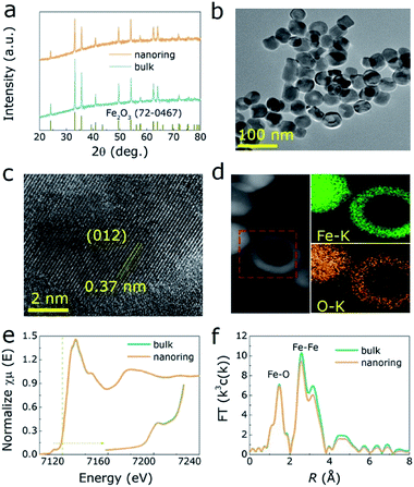
Hexagonal hematite (α-Fe2O3) nanorings (NRs) was prepared by a conventional hydrothermal method.34 Fig. 1a shows XRD pattern of both α-Fe2O3 and bulk one, where all the diffraction peaks correspond to the α-Fe2O3 (PDF no. 72-0467). Further, SEM and TEM were performed to investigate structure and morphology of those samples, where the results indicate that α-Fe2O3 presents homogeneous NRs morphology (Fig. 1b, S1 and S2, ESI†). The length and ring diameter of α-Fe2O3 NRs are 39 nm and 28 nm, respectively (Fig. S3a and b, ESI†). High-resolution TEM (HRTEM) image shows that α-Fe2O3 NRs have clear lattice spacing (0.37 nm, 0.27 nm, 0.25 nm and 0.14 nm) matches well with the (012), (104), (110) and (300) planes, respectively (Fig. 1c and S4, ESI†). Meanwhile, Fe and O elements are uniform distributed in α-Fe2O3 NRs matrix, as illustrated in energy dispersive X-ray (EDX) mapping images (Fig. 1d). To further investigate the change in electronic structure and coordination environment of Fe atoms in both samples, Fe K-edge XANES and EXAFS were measured. As shown in Fig. 1e, especially for the pre-edge peak, the intensity of α-Fe2O3 NRs is significantly reduced compared to the bulk one, confirming the higher local O coordination of the Fe atoms for α-Fe2O3 NRs.35,36 Fig. 1f further displays the corresponding Fourier transforms (FT) of Fe K-edge EXAFS for two samples, where the peaks at 1.4 Å, 2.5 Å, 3.2 Å and 4.7 Å are attributed to the Fe–O, Fe–Fe, Fe–O/Fe coordination in α-Fe2O3 NRs.37 It is of interest that the α-Fe2O3 NRs presents lower intensity than those of bulk ones, revealing the surface distortion and decreased structural homogeneity of bulk α-Fe2O3, corresponding to the results of wavelet transform (WT) simulation with the weaker central intensities for α-Fe2O3 NRs (Fig. S5 and Table S1, ESI†). | ||
| Fig. 1 (a) The XRD pattern of samples. The TEM (b), HRTEM (c) and EDX mapping images (d) of α-Fe2O3 NRs. The XANES spectra (e) and corresponding FT EXAFS (f) of Fe K-edge for two samples. | ||
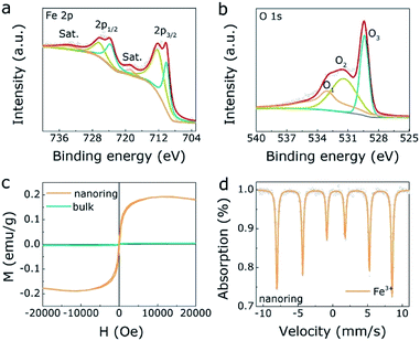
Besides, Fig. 2a presents the XPS results of Fe 2p spectrum, where the main peaks (726.4 eV, 712.4 eV) are 2p1/2 and 2p3/2 of Fe3+, respectively. Besides, the minor peaks (723.8 eV, 710.2 eV) are Fe2+,36 revealing there are some structural dislocation of the α-Fe2O3 NRs surface. For the O 1s result (Fig. 2b), the three peaks (O1, O2, O3) correspond to surface adsorbed oxygen, oxygen vacancy and metal–oxygen peaks, respectively, where the appearance of oxygen vacancy gives rise to the structural dislocation of the α-Fe2O3 NRs surface. Meanwhile, there is no oxygen vacancy in bulk α-Fe2O3 sample (Fig. S6, ESI†). Furthermore, M(H) hysteresis loops of the α-Fe2O3 NRs and bulk α-Fe2O3 were measured at room temperature to evaluate the magnetic property. As displayed in Fig. 2c, α-Fe2O3 NRs owns the saturation magnetization (Ms) of 0.19 emu g−1 and the coercivity (Hc) of 90 Oe, indicating the unique ferromagnetic interaction in α-Fe2O3 NRs. On the contrary, the bulk α-Fe2O3 exhibits antiferromagnetic property. These results reflect a magnetic transition of the α-Fe2O3 from antiferromagnetic to ferromagnetic nature, which mainly ascribed to the structural dislocation of the α-Fe2O3 NRs surface, in agreement with the XPS results. Mössbauer spectra and related parameters (Table S2, ESI†) were also investigated to confirm Fe valence states of both α-Fe2O3 NRs and bulk one. As displayed in the Fig. 2d and S7 (ESI),† the fitting results demonstrate that the dominated valence state is Fe3+ in both α-Fe2O3 NRs and bulk one.
 | ||
| Fig. 2 The XPS spectrum of Fe 2p (a) and O 1s (b) for α-Fe2O3 NRs. (c) The magnetization hysteresis loops of α-Fe2O3 NRs and one. (d) The Mössbauer spectrum of α-Fe2O3 NRs. | ||
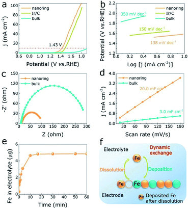
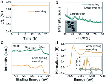
The OER activities of α-Fe2O3 NRs, bulk α-Fe2O3 and Ir/C under acidic media (1 M HCl) were investigated by three-electrode device. Linear voltammetry scanning (LSV) curves of all electrocatalysts as exhibited in Fig. 3a and S8 (ESI†), where α-Fe2O3 NRs shows predominant OER performances with lower overpotential (1.43 V) than Ir/C (1.48 V) and bulk α-Fe2O3 (1.89 V) at 10 mA cm−2, also the influence of electrocatalyst free substrate has been eliminated (Fig. S9, ESI†). Correspondingly, the Tafel slope values of α-Fe2O3 NRs, Ir/C, and bulk α-Fe2O3 are 138 mV dec−1, 150 mV dec−1, and 350 mV dec−1, respectively, demonstrating that the α-Fe2O3 NRs owns the excellent intrinsic OER activity (with the lowest Tafel slope value) in acidic solution (Table S3, ESI†). In addition, the α-Fe2O3 NRs exhibits increased electrical conductivity with smaller charge transfer resistance (Rct, 96 ohm) than bulk one (282 ohm), as illustrated in Fig. 3c. Moreover, Fig. 3d show the double layer capacitance (Cdl) of electrocatalysts, which is examined to assess effective electrochemical active surface area (ECSA). The Cdl value of α-Fe2O3 NRs is about 7 times larger than that of the bulk one, indicating the α-Fe2O3 NRs electrocatalyst can expose more active sites for OER process. A larger TOF value of 2.3 O2 s−1 at 1.7 V is obtained for the α-Fe2O3 NRs, compared to 1.3 O2 s−1 for bulk one (Fig. S10a, ESI†), demonstrating the nanoring morphology has a great influence on the OER performances in α-Fe2O3. Distinctly, a rapid dissolution reaction of the α-Fe2O3 NRs occurs at the beginning of OER process under acidic condition, as displayed in the inductively coupled plasma mass spectrometry (ICP-MS) analyses (Fig. 3e), indicating that Fe atoms on the electrode surface are dynamic. It is of interest that after cyclic voltammetry (CV) cycling of 16.6 min, this dissolution rate reaches its maximum and keeps stable (4.8 μg), corresponding to the excellent OER activities as described above, demonstrating the formation of prominent α-Fe2O3 NRs electrocatalyst with high activity and dynamic stability (Fig. 3f). In addition, chronoamperometric response and CV cycling test display that the current loss and overpotential increase negligibly after 22 h continuous operation (Fig. 4a, S10b and c, ESI†), further demonstrating the superior OER stability under acidic condition. Both XRD pattern, TEM image, XPS spectra of Fe 2p, XANES and FT of Fe K-edge EXAFS of α-Fe2O3 NRs after long-time stability test shown in Fig. 4b–d, further exhibit well-retained crystallinity and electrocatalytic durability. These analyses confirm that the low-cost α-Fe2O3 NRs can effectively optimize the OER in acidic medium.
Conclusions
In summary, we developed uniform α-Fe2O3 NRs as efficient OER electrocatalyst in acidic conditions with lower overpotential and robust durability. The promoted performance is mainly caused by the unique nanoring structure and disordered surface, which accelerates electron transfer, offers a large active surface area and great electrical conductivity (based on Tafel slope, Cdl and EIS results), giving rise to the boosted intrinsic electrocatalytic activity. This realizable finding provides a facile strategy to explore new hematite-based electrocatalysts with excellent performance and great stability for portable energy storage and conversion system.Conflicts of interest
There are no conflicts of interest to declare.Acknowledgements
This work is supported by the National Natural Science Foundation of China (Grant No. 11474137).Notes and references
- L. C. Seitz, C. F. Dickens, K. Nishio, Y. Hikita, J. Montoya, A. Doyle, C. Kirk, A. Vojvodic, H. Y. Hwang and J. K. Norskov, Science, 2016, 353, 1011–1014 CrossRef CAS.
- M. Q. Yang, J. Wang, H. Wu and G. W. Ho, Small, 2018, 1703323 CrossRef.
- H. Wu, J. Geng, H. Ge, Z. Guo, Y. Wang and G. Zheng, Adv. Energy Mater., 2016, 6, 1600794 CrossRef.
- C. Tang, H. S. Wang, H. F. Wang, Q. Zhang, G. L. Tian, J. Q. Nie and F. Wei, Adv. Mater., 2015, 27, 4516–4522 CrossRef CAS.
- C. C. L. Mccrory, S. Jung, I. M. Ferrer, S. M. Chatman and T. F. Jaramillo, J. Am. Chem. Soc., 2015, 137, 4347 CrossRef CAS.
- Y. Matsumoto and E. Sato, Mater. Chem. Phys., 1986, 14, 397–426 CrossRef CAS.
- C. C. L. Mccrory, S. Jung, J. C. Peters and T. F. Jaramillo, J. Am. Chem. Soc., 2013, 135, 16977–16987 CrossRef CAS.
- Z. F. Huang, J. J. Song, Y. H. Du and S. B. Xi, Nat. Energy, 2019, 4, 329–338 CrossRef CAS.
- F. Dionigi and P. Strasser, Adv. Energy Mater., 2016, 1600621 CrossRef.
- C. Roy, B. Sebok, S. B. Scott and E. M. Fiordaliso, Nat. Catal., 2018, 1, 820–829 CrossRef CAS.
- L. Trotochaud, S. L. Young, J. K. Ranney and S. W. Boettcher, J. Am. Chem. Soc., 2014, 136, 6744–6753 CrossRef CAS.
- P. Zhou, Y. Wang, C. Xie, C. Chen, H. Liu, R. Chen, J. Huo and S. Wang, Chem. Commun., 2017, 53, 11778–11781 RSC.
- F. L. Meng, G. Yilmaz, T. P. Ding, M. Gao and G. W. Ho, Adv. Mater., 2019, 31, 1903605 CrossRef.
- D. A. Nedosekin, S. Ayyadevara, R. J. S. Reis, E. I. Galanzha and V. P. Zharov, Proc. Natl. Acad. Sci. U. S. A., 2007, 104, 20142 Search PubMed.
- T. Odedairo, X. C. Yan, X. D. Yao, K. Ken Ostrikov and Z. H. Zhu, Adv. Mater., 2017, 1703792 CrossRef.
- S. Yin, X. Ma and D. E. Ellis, Surf. Sci., 2007, 601, 2426–2437 CrossRef CAS.
- S. Yamamoto, T. Kendelewicz, J. T. Newberg, G. Ketteler and A. Nilsson, J. Phys. Chem. C, 2010, 114, 2256–2266 CrossRef CAS.
- B. Klahr, S. Gimenez, F. Fabregat-Santiago, T. Hamann and J. Bisquert, J. Am. Chem. Soc., 2012, 134, 4294–4302 CrossRef CAS.
- J. Ahmed, T. Ahamad, N. Alhokbany, B. M. Almaswari, T. Ahmad, A. Hussain, E. S. S. Al-Farraj and S. M. Alshehri, ChemElectroChem, 2018, 5, 3938–3945 CrossRef CAS.
- J. Ahmed, T. Ahamad, M. Ubaidullah, A. M. Al-Enizi and S. M. Alshehri, Mater. Lett., 2018, 240, 51–54 CrossRef.
- S. M. Alshehri, J. Ahmed, T. Ahamad, P. Arunachalam, T. Ahmad and A. Khan, RSC Adv., 2017, 7, 45615–45623 RSC.
- C. Yilmaz, C. F. Tan, Y. F. Lim and C. W. Ho, Adv. Energy Mater., 2019, 9, 1802981–1802983 CrossRef.
- Q. Hu, G. Li, G. Li, X. Liu, B. Zhu, X. Chai, Q. Zhang, J. Liu and C. He, Adv. Energy Mater., 2019, 9, 1803861–1803867 Search PubMed.
- N. Danilovic, R. Subbaraman, K. C. Chang, S. H. Chang, Y. J. Kang, J. Snyder, A. P. Paulikas, D. Strmcnik, Y. T. Kim and D. Myers, J. Phys. Chem. Lett., 2014, 5, 2474–2478 CrossRef CAS.
- S. H. Chang, N. Danilovic, K. C. Chang, R. Subbaraman, A. P. Paulikas, D. D. Fong, M. J. Highland, P. M. Baldo, V. R. Stamenkovic and J. W. Freeland, Nat. Commun., 2014, 5, 4191 CrossRef CAS.
- N. Danilovic, R. Subbaraman, K. C. Chang and S. H. Chang, Angew. Chem., Int. Ed. Engl., 2014, 53, 14016–14021 CrossRef CAS.
- T. Binninger, R. Mohamed, K. Waltar, E. Fabbri, P. Levecque, R. Kötz and T. J. Schmidt, Sci. Rep., 2015, 5, 12167 CrossRef CAS.
- M. Huynh, T. Ozel, C. Liu, E. C. Lau and D. G. Nocera, Chem. Sci., 2017, 8, 4779–4794 RSC.
- P. Strasser, Adv. Energy Mater., 2016, 7, 1601275 Search PubMed.
- J. S. Mondschein, J. F. Callejas, C. G. Read, J. Y. C. Chen, C. F. Holder, C. K. Badding and R. E. Schaak, Chem. Mater., 2017, 29, 950–957 CrossRef CAS.
- J. M. Qian, T. T. Wang and D. Q. Gao, Appl. Catal., B, 2019, 250, 71–77 CrossRef CAS.
- L. Zhuang, L. Ge, Y. Yang, M. Li, Y. Jia, X. Yao and Z. Zhu, Adv. Mater., 2017, 29, 1606791–1606793 Search PubMed.
- P. T. Liu, J. Q. Ran, B. R. Xia, S. B. Xi and J. Wang, Nano-Micro Lett., 2020, 12, 1–12 CrossRef.
- X. L. Liu, Y. Yang, C. T. Ng, L. Y. Zhao, Y. Zhang, B. H. Bay, H. M. Fan and J. Ding, Adv. Mater., 2015, 27, 1939–1944 CrossRef CAS.
- B. Zhang, X. Zheng, O. Voznyy, R. Comin, M. Bajdich, M. Garcia-Melchor, L. Han, J. Xu, M. Liu and L. Zheng, Science, 2016, 352, 333–337 CrossRef CAS.
- H. Wu, T. Yang, Y. H. Hua and G. W. Ho, Adv. Mater., 2018, 30, 1804341 CrossRef.
- W. R. Cheng, J. F. He and S. Q. Wei, J. Am. Chem. Soc., 2014, 136, 10393–10398 CrossRef CAS.
Footnote |
| † Electronic supplementary information (ESI) available. See DOI: 10.1039/d0ra04262e |
| This journal is © The Royal Society of Chemistry 2020 |


