 Open Access Article
Toward a disposable low-cost LOC device: heterogeneous polymer micro valve and pump fabricated by UV/ozone-assisted thermal fusion bonding†
Wonjong Junga,
M. Jalal Uddin bc,
Kak Namkoonga,
Wonseok Chungd,
Joon-Ho Kim*e and
Joon S. Shim
 *b
*b
aHealthcare Sensor Lab., Device Research Centre, Samsung Advanced Institute of Technology (SAIT), Samsung Electronics Co., Ltd., Suwon, Gyeonggi-do 16678, Republic of Korea
bBio-IT Convergence Lab., Department of Electronics and Convergence Engineering, Kwangwoon University, Seoul 01897, Republic of Korea. E-mail: shim@kw.ac.kr
cDepartment of Electrical and Electronic Engineering, Islamic University, Kushtia-7003, Bangladesh
dBioNano Health Guard Research Centre, Daejeon 34141, Republic of Korea
eSensor Lab., Smart Device Team, Samsung Research, Samsung Electronics Co., Ltd., Seoul 06765, Republic of Korea. E-mail: mythos.kim@samsung.com; Tel: +82-10-41213075
First published on 29th July 2020
Abstract
Herein, a heterogeneous polymer micro valve and pump with a polypropylene (PP) membrane was developed in a low-cost manner via UV/ozone-assisted thermal fusion bonding. The proposed fabrication technique allowed for a geometrically selective bonding; consequently, the membrane was prevented from bonding with the valve seat of the diaphragm micro-valve, without patterning a protection layer or introducing an additional structure. The developed device withstands 480 kPa of static pressure and up to 350 kPa of a vibration pressure, providing sufficient bonding strength for microfluidic actuations. The fabricated micro valve and pump are fully characterized and compared with a poly(dimethylsiloxane) (PDMS) membrane glass device, showing comparable valving and pumping performance. As a result, the robust PP membrane micro valve and pump are simply implemented in a facile manner, and demonstrated excellent performance, which is highly desirable for mass production of disposable lab-on-a-chip (LOC) devices.
Introduction
For biomedical diagnosis and environmental monitoring, huge demand exists to develop an integrated system for automatically processing small amounts of samples with a fast turnaround time.1–9 Because clinical or environmental samples should be analyzed by a series of biochemical, chemical, and mechanical processes, lab-on-a-chip (LOC) technology has been extensively investigated to conveniently and accurately analyze a sample for a variety of purposes.2,3 Furthermore, multiple laboratory tests for a single sample could be systematically performed with the LOC device, which comprises multiple microfluidic channels and chambers.4,10,11 However, to fabricate a robust and reliable LOC device, an on-chip micro valve and pump should be developed such that samples and reagents can be accurately provided at desired positions in the microfluidic device.12–14Among the various types of micro valves, a monolithic micro valve has been widely utilized due to its reliable valving performance and highly dense integration with microfluidic channels.15–17 In particular, a micro-valve with an elastomeric membrane sandwiched between a fluidic layer and a pneumatic layer demonstrated feasibility for its use various applications of integrated microfluidic systems.17–23 In most of these membrane-based micro valves, poly(dimethylsiloxane) (PDMS) film was utilized as the elastomeric membrane.24,25 However, the substrate materials used for patterning fluidic channels and pneumatic channels are usually limited to glass, because the surface to be bonded with PDMS is restricted to a Si-mediated substrate. These glasses require expensive microfabrication procedures to make etch microscale patterns. To reduce the manufacturing cost, silane coatings on thermoplastics have been investigated.26–29 However, the selective coating of silane to the bonding surface is necessary to avoid a contamination in the fluidic channel region. For economical fabrication of the membrane micro valve, a trial was undertaken to implement a polymer device by UV/ozone (UV/O3)-assisted direct bonding between poly(methyl methacrylate) (PMMA) and PDMS.30,31 Nevertheless, this method could not be universally applied to microfluidic applications because of an insufficient bonding strength.31
In this work, a polypropylene (PP) film, as a membrane layer, was bonded between PMMA substrates that were injection-molded with microchannel patterns, leading to a fully polymerized and low-cost fabrication of monolithically integrated micro valves and pumps. Without using any functional groups, the bonding of the PP membrane to the PMMA substrate was achieved by UV/O3-assisted thermal fusion bonding.32 PP has various advantages over PDMS its use as a membrane in pneumatic actuation. Under the same membrane thickness, PP has much lower gas permeability than PDMS, preventing the generation of air bubbles during pneumatic actuation. In addition, PP has an extremely low water absorption tendency; and thus, there is no loss of sample solution by material absorption during the fluid flow. Moreover, the swelling in PDMS by solvent absorption can thus be avoided in the PP membrane, allowing a wide range of solutions to flow through the developed device.
In this work, a geometry-selective bonding technique was used. The diaphragm-based micro valve has a valve seat where the membrane contacts to open and close the flow path. Thus, when the membrane film is bonded to the fluidic substrate, it should be selectively separated from the valve seat for pneumatic actuation. To achieve this selective bonding of the PP membrane to the PMMA substrate, various studies have been conducted such as selective marking or patterning of the deactivating materials and lowering the height of the valve seat below the substrate.31,33–36 For the economical and simple fabrication of the LOC device, the membrane was selectively bonded to the fluidic substrate without any additional patterning or structuring at the fluidic layer. By utilizing a pattern at the pneumatic layer and polymer deformation during thermal bonding, the membrane was automatically set apart from the valve seat of the fluidic layer. As a result, the developed polymer micro valve and pump can be widely utilized for economical mass production of the monolithic microfluidic devices, realizing various types of fully automated and disposable LOC applications.
Experimental
Device fabrication
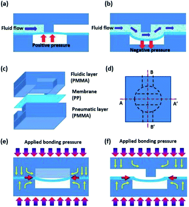
Fig. 1(a) and (b) show the operation principle of the normally closed membrane micro valves. The micro valve controls the fluid flow by applying pneumatic pressure to the elastic membrane, which was sandwich-bonded between the fluidic layer and the pneumatic layer. When positive pressure is applied to the membrane, the membrane deforms and pushes up against the valve seat at the fluidic layer, blocking the fluid flow (see Fig. 1(a)). On the other hand, when negative pressure is applied to the membrane, the membrane has a concave shape and is temporarily separated from the valve seat, allowing the fluid to flow through the fluidic channel (see Fig. 1(b)). To construct the membrane micro valve, the PP film was utilized as a membrane layer and bonded to injection-molded PMMA substrates, where one substrate had fluidic channels and the other substrate had pneumatic channels. To enable the flexible deflection of the membrane, the thickness of the PP film was selected to be 50 μm. The fluidic layer and pneumatic layer were fabricated with PMMA by plastic injection molding at the microstructure patterned nickel (Ni) mold. For the preparation of the Ni mold, Ni electroplating was conducted on the microfabricated glass wafer. After patterning the photoresist by conventional photolithography, the glass wafer was isotropically etched with an etching depth of 100 μm using HF etchant. Following by the removal of the photoresist, 10 nm of chromium (Cr) layer and 100 nm of gold (Au) layer were deposited on the patterned glass by e-beam evaporation. Then, Ni electroplating was performed with at plating thickness of 600 μm. After cutting the Ni mold to be fixed at the injection molding machine, injection molding was conducted with PMMA pellets (Cheil Industries Inc., KR.).UV/O3-assisted thermal fusion bonding
After the PMMA fluidic and pneumatic substrates are prepared by injection molding, the substrates were thermally fusion-bonded with the PP film membrane after UV/O3 treatment.32 Since thermal fusion generally allows bonding between two materials that have similar glass transition temperatures (Tg), heterogeneous materials with different Tg are not strongly bonded by common thermal bonding procedures.To achieve robust bonding between the PP film and the PMMA substrate, each layer was treated with UV/O3 to bond two different thermoplastics at a bonding temperature below their Tg. To prevent bonding between the membrane and the valve seat, the prepared PMMA pneumatic substrate and PP film were bonded first. The bonding surfaces of the PP film and the PMMA substrate were treated by UV/O3 for 5 min (Zeolite Inc, USA). Then, the pneumatic layer and the PP film were bonded using an automatic hot press (CARVER Inc., USA). The detailed conditions for the thermal fusion bonding were a temperature of 55 °C, a pressure of 10 bar, and a bonding time of 5 min. After the completion of the pneumatic layer bonding, the fluidic PMMA layer was aligned with the pneumatic layer and bonded to the opposite side of the PP film by the same procedures and conditions as those used for bonding the PP film and the pneumatic layer.
Geometry-selective bonding
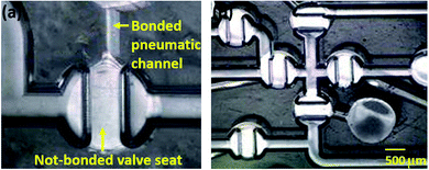
As shown in Fig. 1(c), three layers of heterogeneous polymers require to be bonded together to implement the membrane micro valve. During the bonding process, the membrane could be bonded with the valve seat at the fluidic layer in the normally closed membrane micro valve. Because the membrane itself is pneumatically actuated to perform valve functions, the bonding of the membrane with the valve seat may permanently block the flow path. To avoid membrane bonding during the bonding procedure, the geometry of the pneumatic layer and the polymer deformation were utilized. For the thermal fusion bonding process, both heat and pressure should be applied to thermoplastic materials. A circular chamber pattern above the valve seat of the fluidic layer was used for pneumatic actuation. This pattern ensured that pressure was not applied to the membrane at the valve seat and the membrane at the valve seat region does not bond with the substrates owing to the absence of the bonding pressure. In addition, the PMMA substrate was slightly deformed in the yellow arrow direction during the bonding process, as illustrated in Fig. 1(e) and (f). While the deformed PMMA substrate was extruded into the empty space of the chamber pattern, the PP film was also thrust into the empty region. As a result, the membrane was set apart from the valve seat via a curvature shape, preventing the membrane from selectively bonding to the valve seat. Fig. 2(a) and (b) show the optical microscopic image of the membrane selectively bonded to the substrate. To clarify the difference between a bonded region and an unbonded region, microscopic pictures were taken while the fabricated chip was inclined, resulting in the unbonded regions being brighter than the bonded region due to differences in light reflection.Measurement of the bonding strength
To measure the bonding strength between the PP film and PMMA substrate, a standard peel test was conducted using a universal tensile machine (UTS, Instron Inc., USA).37 Following the ISO 90° peel test instructions, the PP samples were prepared with dimensions of 2 cm wide and 10 cm long, and one side of the PP film was bonded to the PMMA substrate by UV/O3-assisted thermal fusion bonding (see UV/O3-assisted thermal fusion bonding). After the PMMA substrate was firmly fixed to the UTS stage, the other side of the PP film was then clipped to the UTS. While the PP film was pulled upward by the UTS, the tensile force was recorded by the load cell at the clip of the UTS. The bonding force was collected from the measured force when the PP was detached from the PMMA substrate, as described in the ESI.† For each bonding condition, the peel tests were performed three times to attain statistical precision. In this way, the bonding force was characterized with respect to the bonding temperature and UV/O3 treatment time.Instrument setup
To operate the developed device, a control system (LabView Inc., USA) and solenoid valves (Lee Valve Inc., USA) were utilized.28 A house vacuum and pressure were utilized as a pressure source and provided a specific pressure via a LabView-controlled pressure regulator. The solenoid valves controlled the micro valves by opening and closing the connected pressure lines to the house vacuum and pressure. Each solenoid valve was independently actuated via the LabView system with a specific program for valving and pumping operations. After interconnecting the solenoid valves with the pressure lines, a custom-made jig was utilized to operate the membrane micro valve by pneumatic control. The holes in the jig were packaged with a rubber O-ring and tightly contacted to the holes at the pneumatic layers to avoid air leakage.Design and simulation of the membrane pump
Two sizes of pumps were fabricated and fully characterized. The pump chamber shape was a rectangle with a semicircle at each of end. The small pump chamber was 1 mm wide and 2 mm long, and the large pump chamber was 1.3 mm wide and 2.6 mm long. For the implementation of the membrane pump, the film thicknesses of PP and PDMS were selected differently, considering the Young's modulus of each material. Because PP has a higher Young's modulus than PDMS, the membrane thickness was determined to be 50 μm for the PP film and 250 μm for the PDMS film. With the selected thicknesses, the membrane provided appropriate deflections for pumping at an operational pressure of 200 kPa without membrane breakage. The membrane deflections of PP and PDMS were simulated by ABAQUS (ABAQUS Inc., USA) to calculate the pumping rates of the PP and PDMS micro pump. The simulated membrane pumps had the same dimensions as the experimented pumps. The pumping rates were simulated for each size and type of material used for the developed pumps, and the results were compared to the experimental pumping rates.Results and discussion
Characterization of the bonding conditions
The membrane was prevented from bonding with the valve seat via the aforementioned selective bonding technique using the geometry at the pneumatic layer. To achieve geometry-selective bonding, bonding conditions should be characterized. If the thermal fusion bonding was performed at an excessively high temperature or pressure, the deformation of the PMMA substrate was too large, resulting in membrane bonding to the valve seat. On the other hand, when the bonding temperature or pressure was too low, the bonding strength was insufficient to uniformly bond the PP layer with the PMMA substrates. To achieve an appropriate bonding strength for the geometry-selective bonding, the bonding condition was characterized by measuring the bonding strength in terms of the bonding temperature and the UV/O3 treatment time. In these tests, the optimized bonding pressure and the bonding time were set to 1 ton and 5 min, respectively. As shown in Fig. 3(a), the bonding strength was measured according to the bonding temperature. Prior to the bonding procedure, the bonding surface was exposed to UV/O3 for 5 min. The bonding strength between the PP film and the PMMA substrate increased as the bonding temperature increased. Based on the characterization results, the appropriate bonding strength was achieved at a temperature of 50 °C, and that the bonding strength remained constant for higher bonding temperatures. Considering the Tg of PP (110 °C) and PMMA (80 °C), appropriate bonding between two heterogeneous materials was attained at a much lower temperature than their Tg. After the characterization of the bonding temperature, the bonding strength was also measured according to the UV/O3 treatment time. The bonding temperature was fixed at 50 °C. Fig. 3(b) shows the effect of the UV/O3 treatment time on the bonding strength of PP and PMMA. The bonding strength sharply increased after 2 min of the UV/O3 treatment. In addition, the bonding strength remained constant for UV/O3 treatment times longer than 5 min. Based on these analyses, the optimal bonding conditions were concluded to be 5 min of UV/O3 treatment and 50 °C of bonding temperature. These bonding conditions enabled strong bonding between the PP film and the PMMA substrate and minimized the deformation of thermoplastics to avoid bonding the PP membrane to the PMMA valve seat.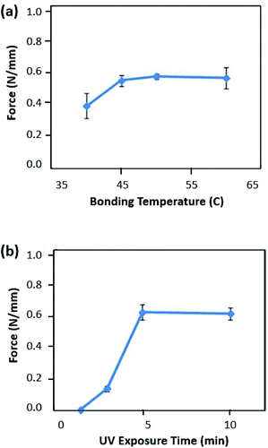 | ||
| Fig. 3 Characterization of bonding strength by UV/O3-assisted thermal fusion bonding according to (a) bonding temperature and (b) UV/O3 treatment time. | ||
Based on the previously reported XPS analysis on the UV/O3 treated PMMA and PP surfaces, there were similar chemical changes on the surface of PP and PMMA after UV/O3 treatment.37,38 Because both polymers contained larger amounts of oxygen components, polar functional groups were generated on the exposed surfaces of PP and PMMA after treatment. These chemical changes at the surface of each polymer provided an adhesion layer, which enabled a low-temperature direct bonding of the heterogeneous polymers between PP and PMMA.
The fabricated device with the optimized bonding conditions withstood at static pressure of more than 480 kPa, which was the maximum pressure that our pressure regulator could withstand. Since we applied the developed device to implement the micro pump by repeatedly actuating the membrane, the maximum vibration pressure was also investigated, in which the developed device could endure during the pumping operation. During the pumping sequences, the membrane was operated at a frequency of 2 Hz. With this frequency, the bonded membrane was vibrated for 10 min. The developed device could endure the pneumatic pumping operation with a vibrating pressure of up to 350 kPa.
Characterization of the polymer surface
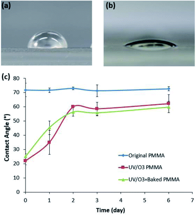
To analyze the surface change of the PMMA by UV/O3 treatment, the contact angle on the PMMA surface was measured over time. To consider a thermal effect during the bonding process, the surface-modified PMMA substrate was baked under the temperature of 50 °C for 5 min. Therefore, three types of PMMA samples were prepared as follows: untreated PMMA, UV/O3-treated PMMA, and the baked PMMA samples after the same UV/O3 treatment. The UV/O3 treatment was performed for 5 min, and the baked sample was placed on the hot plate for 5 min at 50 °C, which was the thermal condition of the bonding process.After the UV/O3 treatment, the PMMA surface was changed to be hydrophilic, as shown in Fig. 4(a) and (b). However, the hydrophilic surface of PMMA recovered to its original state over time. Fig. 4(c) shows the aging characteristics of the UV/O3-treated PMMA. Since the hydrophilic property of PMMA was caused by polar functional groups such as –OH, C![[double bond, length as m-dash]](https://www.rsc.org/images/entities/char_e001.gif) O, and COOH,37 the hydrophobic recovery of UV/O3-treated PMMA suggested that the effect of polar groups disappeared over time. As a result, the side effect of the UV/O3 treatment on the sample solution could be minimized as time passed after the device fabrication.
O, and COOH,37 the hydrophobic recovery of UV/O3-treated PMMA suggested that the effect of polar groups disappeared over time. As a result, the side effect of the UV/O3 treatment on the sample solution could be minimized as time passed after the device fabrication.
Characterization of the valving performance
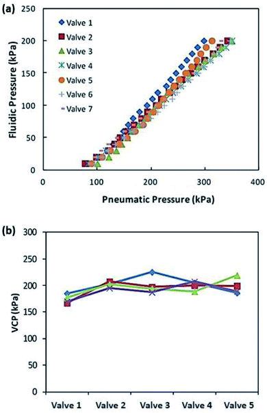
To evaluate the valving performance, the valve-closing pressure (VCP) was measured as shown in Fig. 5(a), where the minimum pneumatic pressure was recorded to block the air-flow via the fluidic pressure. For this measurement, while the pressured air was provided to the inlet of the microchannel, the tube from the microchannel outlet was submerged in DI water to check air leakage. As long as the air bubble at the end of the outlet tube was detected, the pneumatic pressure was slowly reduced. The minimum pressure to block the air-flow without leakage was recorded as the VCP for each fluidic pressure. As the fluidic pressure increased, a higher pneumatic pressure was required for closing the valve with a linear relationship. Additionally, the tested valves showed a small deviation to block the air flow at the same fluidic pressure, enabling a stable valve operation when the developed valve would be applied to the device with multiple valves. To check the chip-to-chip variation and deviations in valve performance, 20 valves from 4 different chips were tested. All the valves have the same dimensions of valve seat width and valve diameter. While applying the fluidic pressure of 100 kPa, the VCPs of each valve were measured. As depicted in Fig. 5(b), a pneumatic pressure of 200 kPa ± 30 kPa was required to block the air flow with 100 kPa of the fluidic pressure.Demonstration of the pumping performance
The monolithic micro pump with the PP membrane was realized by sequentially operating 2 valves and 1 chamber (see Fig. 6(a)), and characterized in comparison to the PDMS-membrane micro pump. Because the pumping rate and the membrane deflections were dependent on the pump size, two pump types with dimensions of 1 mm × 2 mm and 1.3 mm × 2.6 mm were tested. Fig. 6(b and c) shows real-time pictures of reagent movements by the membrane micro pump. The developed micro pump moved the reagent to the reservoir, which had cross-sectional dimensions of 1 mm wide and 0.7 mm high. Further, 3.5 μL (by volume) of reagent was successfully delivered to the reservoir within 30 s, which is a desirable pumping rate for microfluidic LOC applications.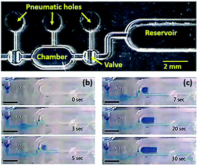 | ||
| Fig. 6 (a) PP membrane micro pump consisting of two micro valves and a micro chamber. (b and c) Operation images of the PP-membrane micro pump to a reservoir (3 mm scale bar). | ||
As plotted in Fig. 7(a), the pumping volumes of the PP device and the PDMS device were recorded according to the pumping cycle. In addition, the pumping rates of each device were compared to the simulated results, as plotted in Fig. 7(b). Because the PP film has lower elasticity than the PDMS, the PP film membrane undergoes a smaller deflection than PDMS membrane at the same pneumatic pressure. Thus, the membrane micro pump with PP film produced a lower pumping rate than the one with PDMS, as plotted in Fig. 7(a). Pumping volume due to membrane deflection increased as the diameter of the membrane increased; thus, a larger diameter of the pump caused a higher pumping rate. Although the PDMS membrane was more easily deflected than the PP film membrane, the membrane deflection was limited by the height of the chamber pattern. As depicted in Fig. 7(b), the PP-film pump provided 60% of the pumping rate of the PDMS film pump at 200 kPa of pneumatic pressure. Considering that the pumping rate of the small PP pump (1 mm × 2 mm) was 27% of that of the PDMS pump, the pumping rate of the PP membrane pump is increased sharply with the pump size.
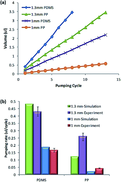 | ||
| Fig. 7 Characterization of the pumping performance. (a) Pumping volume according to pumping cycle and (b) pumping rate comparison between PDMS and PP membranes. | ||
Fig. 7(b) also shows the comparison of the simulated pumping rate with the experimental result. Consistent with the experimental results, the membrane micro pump with PDMS membrane provided a higher pumping rate than the PP film pump. The pumping rate difference between the PDMS membrane and PP membrane decreased as the size of the pump increased. It is noteworthy that the experimental pumping rate of the PP film was much higher than the simulated pumping rate. The difference between the experimental results and the simulation results was mainly attributed to the polymer deformation during the fusion bonding procedure. Due to the high pressure and temperature, the intermediate PP membrane protruded inward owing to polymer deformation, as shown in Fig. 1(e) and (f). Thus, the PP membrane at the valve and the pump had a curved shape, leading to a larger deflection of the PP membrane than the simulated PP membrane. Due to this geometrical curvature, the PP membrane in the experimental device produced a larger pumping rate than that in the simulation.
Conclusions
In this work, a highly functional membrane micro valve and pump was successfully fabricated with a PP film and injection-molded PMMA substrate, realizing an economical and disposable LOC device. The PP film was directly bonded to the PMMA substrate by UV/O3-assisted thermal fusion bonding, which enabled strong bonding between heterogeneous materials with different Tg values. Furthermore, the performance of the developed devices has been characterized in comparison to the PDMS-glass device, showing a comparable valving and pumping performance. Thus, the developed device is very desirable to implement various applications of polymer LOCs, such as a disposable-type of device for clinical diagnostic device.Conflicts of interest
There are no conflicts of interest to declare.Acknowledgements
The authors gratefully acknowledge the support for this work provided by a 2019 Kwangwoon Research Grant. The work reported in this paper was partly conducted during the sabbatical year of Kwangwoon University in 2019. This research was also supported by the Basic Science Research Program through the National Research Foundation of Korea (NRF), funded by the Ministry of Education (no. NRF-2018R1D1A1B07050677), and the Korea Health Technology R&D Project through the Korea Health Industry Development Institute (KHIDI), funded by the Ministry of Health & Welfare, Republic of Korea (Grant no. HI18C1839).Notes and references
- C. Dincer, R. Bruch, E. Costa-Rama, M. T. Fernández-Abedul, A. Merkoçi, A. Manz, G. A. Urban and F. Güder, Adv. Mater., 2019, 31, 1806739, DOI:10.1002/adma.201806739.
- F. Long, A. Zhu and H. Shi, Sensor, 2013, 13(10), 13928–13948 CrossRef CAS PubMed.
- J. Yin, Y. Suo, Z. Zou, J. Sun, S. Zhang, B. Wang, Y. Xu, D. Darland, J. X. Zhao and Y. Mu, Lab Chip, 2019, 19, 2769–2785 RSC.
- M. Jalal Uddin and J. S. Shim, Anal. Chem., 2019, 91, 2686–2694 CrossRef PubMed.
- Q. He, J. Liu, X. Liu, G. Li, D. Chen, P. Deng and J. Liang, Electrochim. Acta, 2019, 296, 683–692 CrossRef CAS.
- Q. He, Y. Wu, Y. Tian, G. Li, J. Liu, P. Deng and D. Chen, Nanomaterials, 2019, 9, 115, DOI:10.3390/nano9010115.
- Y. Wu, P. Deng, Y. Tian, Z. Ding, G. Li, J. Liu, Z. Zuberi and Q. He, Bioelectrochemistry, 2020, 131, 107393, DOI:10.1016/j.bioelechem.2019.107393.
- Q. He, Ya. Tian, Y. Wu, J. Liu, G. Li, P. Deng and D. Chen, Nanomaterials, 2019, 9(3), 429, DOI:10.3390/nano9030429.
- Q. He, J. Liu, X. Liu, G. Li, D. Chen, P. Deng and J. Liang, Nanomaterials, 2018, 8(4), 194, DOI:10.3390/nano8040194.
- J. T. Nevill, R. Cooper, M. Dueck, D. N. Breslauer and L. P. Lee, Lab Chip, 2007, 7, 1689–1695 RSC.
- J. Y. Choi and T. S. Seo, Biotechnol. J., 2009, 4, 1530–1541 CrossRef CAS PubMed.
- K. W. Oh and C. H. Ahn, J. Micromech. Microeng., 2006, 16, R13–R39 CrossRef.
- I. S. Bin, M. Jalal Uddin, G. J. Jin and J. S. Shim, Lab Chip, 2018, 18, 1310–1319 RSC.
- M. Jalal Uddin, G. J. Jin, K. S. Eom, M. H. Kim and J. S. Shim, Bioelectrochemistry, 2018, 122, 221–226 CrossRef CAS PubMed.
- E. Yildirim, M. A. Sahir Arıkan and H. Kulah, Sens. Actuators, A, 2012, 181, 81–86 CrossRef CAS.
- A. Gunda, G. Ozkayar, M. Tichem and M. K. Ghatkesar, Micromachines, 2020, 11(2), 130, DOI:10.3390/mi11020130.
- W. H. Grover, M. G. von Muhlen and S. R. Manalis, Lab Chip, 2008, 8, 913–918 RSC.
- W. H. Grover, A. M. Skelley, C. N. Liu, E. T. Lagally and R. A. Mathies, Sens. Actuators, B, 2003, 89, 315–323 CrossRef CAS.
- B. Mosadegh, T. Bersano-Begey, J. V. Park, M. A. Burns and S. Takayama, Lab Chip, 2011, 11, 2813–2818 RSC.
- X. Zhang and A. E. Oseyemi, Micromachines, 2019, 10, 798, DOI:10.3390/mi10120798.
- W. H. Grover, R. H. C. Ivester, E. C. Jensen and R. A. Mathies, Lab Chip, 2006, 6, 623–631 RSC.
- J. Rupp, M. Schmidt, S. Münch, M. Cavalar, U. Steller, J. Steigert, M. Stumber, C. Dorrer, P. Rothacher, R. Zengerle and M. Daub, Lab Chip, 2012, 12, 1384–1388 RSC.
- B. Mosadegh, C.-H. Kuo, Y.-C. Tung, Y. Torisawa, T. Bersano-Begey, H. Tavana and S. Takayama, Nat. Phys., 2010, 6, 433–437 Search PubMed.
- M. Jalal Uddin, M. K. Hossain, M. I. Hossain, W. Qarony, S. Tayyaba, M. N. H. Mia, M. F. Pervez and S. Hossen, Results Phys., 2017, 7, 2289–2295 Search PubMed.
- A. Vohra, K. Schlingman, R. S. Carmichael and T. B. Carmichael, Chem, 2018, 4(7), 1673–1684 CAS.
- M.-E. Vlachopoulou, A. Tserepi, P. Pavli, P. Argitis, M. Sanopoulou and K. Misiakos, J. Micromech. Microeng., 2009, 19, 015007, DOI:10.1088/0960-1317/19/1/015007.
- P. Gu, K. Liu, H. Chen, T. Nishida and Z. H. Fan, Anal. Chem., 2010, 83, 446–452 CrossRef PubMed.
- N. Y. Lee and B. H. Chung, Langmuir, 2009, 25, 3861–3866 CrossRef CAS PubMed.
- K. S. Lee and R. J. Ram, Lab Chip, 2009, 9, 1618–1624 RSC.
- W. Zhang, S. Lin, C. Wang, J. Hu, C. Li, Z. Zhuang, Y. Zhou, R. A. Mathies and C. J. Yang, Lab Chip, 2009, 9, 3088–3094 RSC.
- I. R. G. Ogilvie, V. J. Sieben, B. Cortese, M. C. Mowlem and H. Morgan, Lab Chip, 2011, 11, 2455–2459 RSC.
- C. W. Tsao, L. Hromada, J. Liu, P. Kumar and D. L. DeVoe, Lab Chip, 2007, 7, 499–505 RSC.
- B. Mosadegh, H. Tavana, S. C. Lesher-Perez and S. Takayama, Lab Chip, 2011, 11, 738–742 RSC.
- H. Lai and A. Folch, Lab Chip, 2011, 11, 336–342 RSC.
- Adhesivess Peel test for a flexible-bonded 95 to-rigid test specimen assemblys Part 1: 90° peel, International Organization for Standardization, Geneva, 2006, https://www.iso.org/standard/43775.html, accessed on 02 January, 2020 Search PubMed.
- C.-S. Park, K.-Y. Hwang, W. Jung, K. Namkoong, W. Chung, J.-H. Kim and N.-H. Huh, J. Micromech. Microeng., 2014, 24, 027002, DOI:10.1088/0960-1317/21/8/085028.
- H. Shinohara, T. Kasahara, S. Shoji and J. Mizuno, J. Micromech. Microeng., 2011, 21, 085028, DOI:10.1088/0960-1317/21/8/085028.
- H. Shinohara, T. Kasahara, S. Shoji and J. Mizuno, J. Micromech. Microeng., 2011, 21(8), 085028, DOI:10.1088/0960-1317/21/8/085028.
Footnote |
| † Electronic supplementary information (ESI) available: Characterization of bonding strength based on the peel off test, bonding temperature and UV/O3 exposure time. See DOI: 10.1039/d0ra03830j |
| This journal is © The Royal Society of Chemistry 2020 |

