
 Open Access Article
 This Open Access Article is licensed under a
 Creative Commons Attribution 3.0 Unported Licence
Unidirectional growth of organic single crystals of naphthalene, anthracene and pyrene by isothermal expansion of supercritical CO2†
Antaram Sarvea,
Jimil Georgeb,
Santosh Agrawalc,
Raksh Vir Jasrac and
Pradip Munshi *c
*c
aDepartment of Chemical Engineering, Sardar Vallabhbhai National Institute of Technology, Surat, 395007, India
bDepartment of Chemistry, Cochin University of Science and Technology, Cochin, Kerala 682022, India
cResearch Centre, Reliance Technology Group, Reliance Industries Limited, Vadodara, Gujarat 391346, India. E-mail: pradip.munshi@ril.com
First published on 11th June 2020
Abstract
Unidirectional single crystals without grain boundaries are highly important in optoelectronic applications. Conventional methods to obtain such crystals involve organic solvents or seed crystals, which have numerous drawbacks. We present here a supercritical CO2-mediated method of the single crystal formation of naphthalene, anthracene and pyrene on the (001) plane without using seed crystals. Single dominant peaks in powder XRD (PXRD) with low full width at half maxima (FWHM) are described. The dependency of crystal size on the rate of depressurization was measured by precise and isothermal expansion of scCO2 solutions. The experimental setup is illustrated for continuous preparation without emission of CO2 or discharge of material into the environment. The materials are shown to be fully converted into crystals indicating a rapid, scalable and environmentally benign process of single crystal formation with practically nil E factor.
1. Introduction
Unknown to date, the masoning of molecules is demonstrated by growing organic crystals (naphthalene, anthracene and pyrene) unidirectionally on the (001) plane through isothermal expansion of a supercritical CO2 (scCO2) solution (Fig. 1a). Unidirectional single crystals1 without grain boundaries have huge potential and are highly important in optoelectronic applications,2 and of course are highly demanded in the preparation of advanced materials, namely for data storage, communication high energy lasers and electro-optic switches.3 Uniform deposition under the unit face with minimum grain boundaries and maximum gain in Gibbs free energy is a prerequisite for getting a perfect crystal.4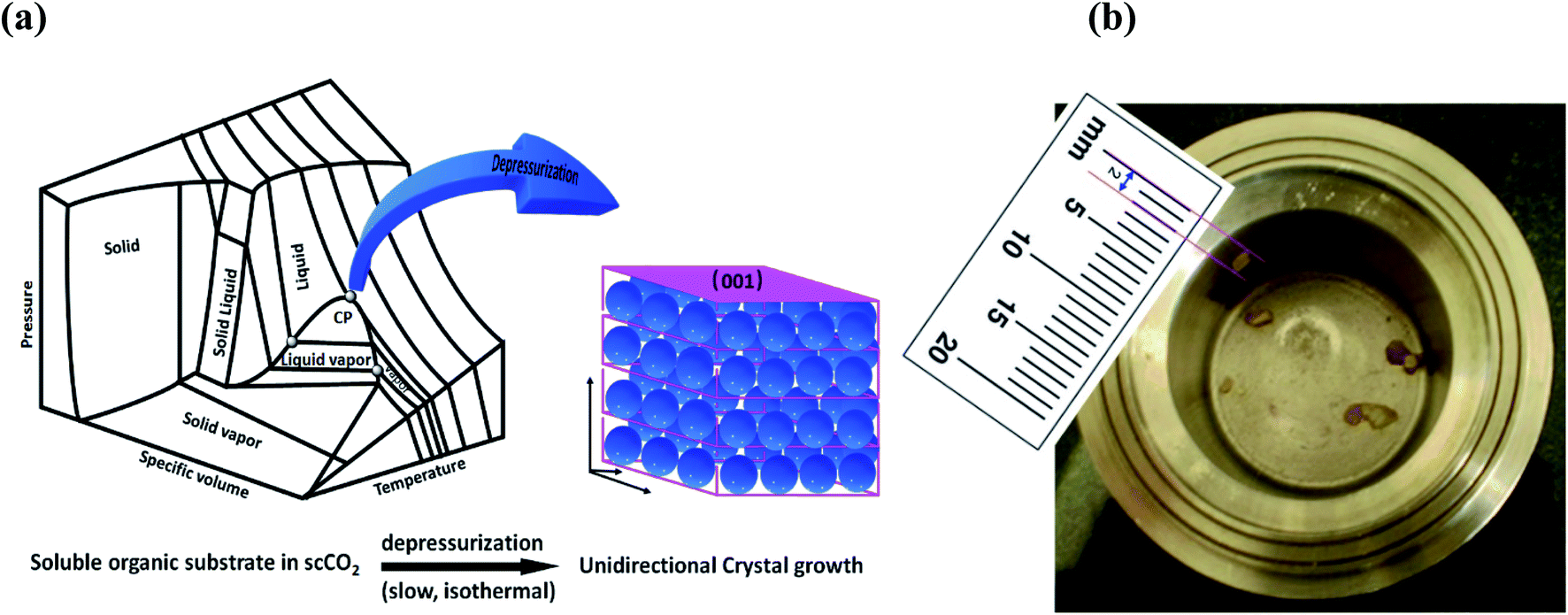 | ||
| Fig. 1 (a) Schematic representation of unidirectional crystal formation in the supercritical region. (b) Anthracene crystal formed inside the vessel. | ||
The ability to grow unidirectional large single crystals is one of the essential criteria to satisfy the needs of science and technology.1,5 In academia, single crystals are unavoidably considered as one of the fundamental requirements6 to reveal the absolute molecular arrangements.7 However, the solvent diffusion and vapor deposition methodologies that are commonly used have genuine drawbacks, like solvent usage, solvent inclusion, uncertainty in getting perfect crystals, grain boundaries etc.8 Crystallization is a thermodynamic preference of solute molecules from solution in which viscosity (η) and surface tension (γ) play vital roles. These properties are almost unchangeable for organic solvents and have very stringent requirements to generate the requisite thermodynamic conditions for crystallization. On the other hand, for supercritical fluids (SCFs) these properties are tunable and can achieve the necessary supersaturation to facilitate the process of primary nucleation, which is essential for crystallization.9
SCFs have numerous applications in material processing and crystallization due to their unique properties, namely high diffusivity (diffusion coefficient 70![[thin space (1/6-em)]](https://www.rsc.org/images/entities/char_2009.gif) 000 m2 s−1), high compressibility and higher solvency.10 It was perhaps Hannay and Hogarth who first observed particle formation from a supercritical solution in 1879.11 They described the phenomenon as ‘formation of snow’. However, this pioneering finding was unnoticed for about 100 years until Krukonis in 1985 took an interest and investigated the economic viability of supercritical fluid-mediated processes.12 Smith and coworkers later referred to the process as ‘rapid expansion of supercritical solutions’ (RESS).13
000 m2 s−1), high compressibility and higher solvency.10 It was perhaps Hannay and Hogarth who first observed particle formation from a supercritical solution in 1879.11 They described the phenomenon as ‘formation of snow’. However, this pioneering finding was unnoticed for about 100 years until Krukonis in 1985 took an interest and investigated the economic viability of supercritical fluid-mediated processes.12 Smith and coworkers later referred to the process as ‘rapid expansion of supercritical solutions’ (RESS).13
Post the discovery of RESS, many reports cite crystallization through a SCF. Supercritical CO2 (scCO2) has additional advantages because it is a green solvent14–16 and has an easily attainable critical temperature (Tc 31.0 °C) and pressure (Pc 73.8 bar), primarily for smaller or nanoparticle generation.17 Gas anti-solvent (GAS) or solution anti-solvent (SAS) are other techniques commonly used to generate small particles from SCFs. These methods have been progressively extended to polymer nucleation as well.18 Several theories have been put forward for proper modelling of particle formation in scCO2.19,20 However, there are only a few reports in the literature regarding single crystal formation in scCO2, as detailed below.
Slow expansion of supercritical CO2 solution (SESS) was carried out by Tai and Cheng21,22 in 1995, and they obtained 2 mm naphthalene crystals in the presence of a seed crystal. Not much detail about the nature of the crystal was disclosed. Later, Raveendran et al.23 in 2005 prepared single crystal of a carbohydrate solution in CO2 through SESS. About a decade later, Pessi et al. revealed a subsidiary technique named controlled expansion of supercritical solution (CESS), which primarily provides larger nanoparticles with narrow particle distribution at a slow rate of expansion.24 The hydrothermal route of single crystal formation is very popular for inorganic and metal–organic framework (MOF)-type materials, and occurs mainly in super or sub-critical water, but no organic molecules have been reported so far, perhaps due to high temperature.25
It is worth mentioning a few literature reports that are loosely relevant to CO2-mediated single crystal formation. MgCO3 from a reaction of molten sodium with CO2 at 550 °C,26 and Fe-ferrocene27 are a couple of available examples of single crystal formation in scCO2. Diamond is reported to be recrystallized in CO2 by in situ reduction of CO2.28 Uchida29 obtained naphthalene crystals in CO2 in the presence of a seed crystal, attaining supersaturation by varying the concentration and temperature. However, the above literature reports lack precise control of the temperature and rate of expansion, and that is what inspired the present study.
We have observed that isothermal, slow and precise expansion of supercritical CO2 solutions of naphthalene, anthracene and pyrene at mild temperatures can generate unidirectional single crystals selectively on the (001) plane (Fig. 1a and b), without introducing any seed crystals, which was not revealed earlier. Such conditions of supercritical fluids provide a better environment to attain large-size unidirectional crystal formation, as shown in Fig. 1a in the three dimensional phase diagram of CO2.30 In fact, this method is direct, rapid and environmentally benign, energy efficient, and holds promise for continuous production recycling the CO2 with practically nil E factor, which is the ratio of waste to product mass.31 This has huge potential in the organic scintillator market, which is expected to reach 480 million USD by 2020 with a 5.6% compound annual growth rate (CAGR).32 Other related potential market areas include organic semiconductor materials and field effect transistors (FETs).33
2. Experimental
2.1. Materials and characterization
The high pressure reactor was purchased from Parr Instrument company, USA. The gas booster, Haskel Model AG 160, was purchased from Haskel, Accudyne Industries Brand, USA. XRD was performed on a Bruker, Model D8 ADVANCE, with Cu K-α beam radiation. The generator was operated at 40 kV and 40 mA, with step size = 0.02° 2θ and a counting time of 5 seconds, and the data were analyzed through Defrac.Suite EVA software. Diffracted X-rays were recorded on a scintillation counter detector. SEM was performed on an FEI Ltd Model Nova NanoSEM 450. The flowmeter was purchased from Cole-Parmer, USA. The vernier scale used to measure the crystal length was a Mitutoyo, Model CD 12" PSX. CO2 and air cylinders were purchased from Ultra Pure Gases (I) Pvt. Ltd. India. The full width at half maximum (FWHM) was calculated using Origin Pro 9.1 64-bit software.Naphthalene, anthracene and phenanthrene were purchased from Sigma-Aldrich Inc. Anal. Grade and used without further purification. Compressed CO2 was purchased from Praxair India, with >99.5% purity.
2.2. Preparation of crystals through slow expansion of a supercritical CO2 solution
In a typical experiment, 2 g of anthracene was taken in a 100 mL Parr reactor and gently flashed with air and CO2. An air driven gas booster was connected with the cylinder and switched on, and CO2 was pumped into the reactor. The desired pressure was obtained with accuracy ±2 bar. The temperature of the reactor was maintained at 45 °C ± 2 °C. Stirring was started and continued for 1 h. The outlet of the vessel was connected to the flowmeter with 10 mm tubing. The vessel was left for 1 h to equilibrate the solution at the set temperature. Slow depressurization was started by opening the valve at a constant temperature. The gas was measured with respect to time as collected though a pneumatic trough (Fig. S1†). After complete depressurization, the vessel was carefully opened and the crystals collected. The crystals were collected for characterization. A schematic drawing of the experimental set up is shown in Fig. 2.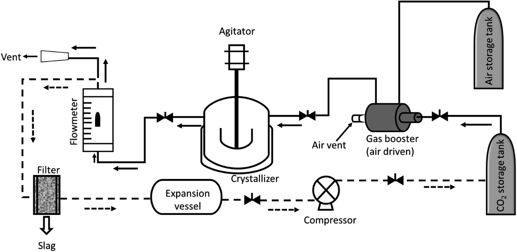 | ||
Fig. 2 Experimental set up used for crystallization. The crystallizer is jacketed and connected to a polyscience water chiller to maintain a constant temperature. Dotted line (![[dash dash, graph caption]](https://www.rsc.org/images/entities/char_e091.gif) ) represents a proposed set up for continuous preparation. ) represents a proposed set up for continuous preparation. | ||
Some powder was left, which could not be converted into crystals. As a result, the crystals were separated from the powders manually, as much as possible, and weighed. The yield calculation was done based on the crystals obtained against initial weight of material taken. The yield of the crystals calculated as percent mass transformation is shown in Table 1. Other substrates (naphthalene and pyrene) are represented in a similar fashion.
| Sample | XRD intensity (001)b [counts per second] | Crystal lengthc [mm] | FWHMd | Depressurization rate [mL per min] | % Yielde [(Wc/W0) × 100] |
|---|---|---|---|---|---|
| a CO2 120 bar, temp. 45 °C.b XRD intensity considered for the peak corresponding to the (001) face.c Length measured using a Vernier scale (Mitutoyo), with average error ±0.5.d FWHM determined using Origin Pro 9.1.e W0 initial weight, Wc weight of crystal. Naphthalene (W0 2.012 g, Wc 1.35 g); anthracene (W0 2.008 g, Wc 0.92 g); pyrene (W0 2.017 g, Wc 0.66 g). | |||||
| Naphthalene | 16881 |
3.00 | 0.0856 | 10 | 67.09 |
| 7256 | 1.66 | 1.2512 | 20 | ||
| Anthracene | 100000 |
2.00 | 0.0689 | 10 | 45.8 |
| 2800 | 1.37 | 0.3275 | 20 | ||
| 130 | 0.12 | — | 50 | ||
| Pyrene | 15250 |
3.33 | 0.0823 | 10 | 32.7 |
A similar experiment was done without taking the organic substrate and monitoring the temperature and pressure. It was observed that there is no observable change in temperature during depressurization. This indicates that cooling or temperature fluctuations due to depressurization do not significantly affect crystal formation, or it could be that the minute heat fluctuations were eliminated by the insulation jacket equipped to the crystallizer vessel.
For a continuous process, the experimental set up is proposed as described in Fig. 2 (dotted line). The vent of the flow meter could be connected to the expansion vessel via a filter or separator to remove the particulates, if any. The expanded gas could be compressed through a compressor and used back in the cycle.
To utilize all of the material in crystal formation, the powder left was used in the next experiment with an additional amount of the same substrate. The experiment continued in a similar fashion, as described.
3. Results
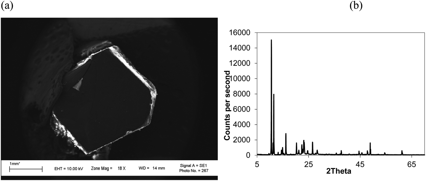
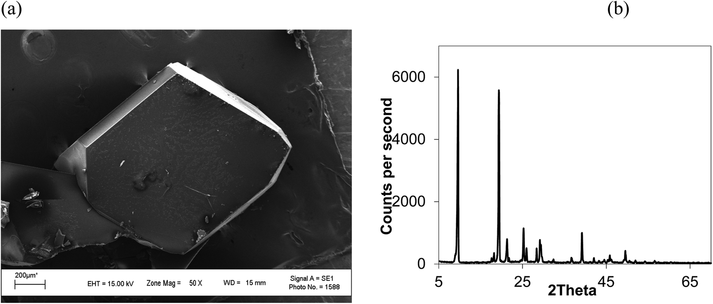
Isothermal depressurization of supercritical CO2 solutions (namely naphthalene, anthracene, pyrene) yields large size single crystals up to 3.33 mm in length unidirectionally on the (001) plane (Table 1). After depressurization, good shiny crystals were obtained, as shown in Fig. 2b. Powder XRD of the anthracene crystal after depressurization shows (Fig. 3a) a very high intensity (100000 counts per second) majorly dominating peak at 2θ of 9.5°, corresponding to the (001) plane of anthracene,34 which is evidence of a high degree of crystallinity and unidirectional growth along the (001) plane.35 The FWHM of this peak determined from the rocking curve (reveals broadening of the XRD peak) is 0.0689 (Fig. 3b), indicating that the crystals have less dislocation densities, minimum grain boundaries,33,35 larger size and higher strength.36 The SEM image of the anthracene crystal shown in Fig. 4a depicts the cuboid shape of the crystal with sharp edges. Fig. 4b displays a representative plot of anthracene crystal size versus depressurization rate. In a similar manner, naphthalene and pyrene crystals were obtained with a length of 3 mm and 3.33 mm, respectively (Fig. S2a† and Fig. 5a, respectively). The singly dominating intense XRD peak of naphthalene observed at 2θ 13.95° (Fig. S2b†) matches with the literature value of 14.0°,37 and that of pyrene observed at 2θ 10.6° (Fig. 5b) matches with the literature value of 10.6°,38 designated as (001) plane reflections. The FWHM values of these crystals are 0.0856 and 0.0823, respectively.
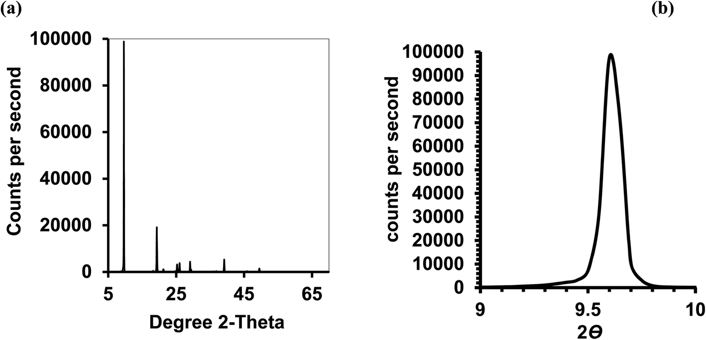 | ||
| Fig. 3 Anthracene crystal; CO2 120 bar, temp. 45 °C, depressurization 10 mL per min. (a) Powder XRD of (b) the rocking curve. | ||
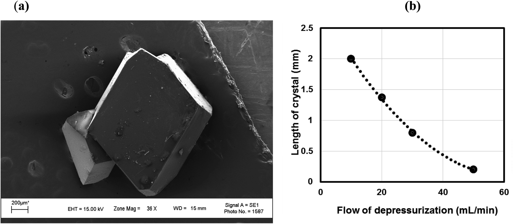 | ||
| Fig. 4 (a) SEM picture of an anthracene crystal. CO2 120 bar, temp. 45 °C, depressurization 10 mL per min. (b) Length of the anthracene crystal monitored with respect to rate of depressurization. CO2 120 bar, temp. 45 °C. | ||
 | ||
| Fig. 5 (a) SEM image and (b) XRD of a pyrene crystal. CO2 120 bar, temp. 45 °C, depressurization 10 mL per min, FWHM for 2θ 10.55° (001) 0.0823. | ||
Unlike rapid expansion of supercritical solution (RESS), the particle size of the crystal is inversely proportional to the rate of expansion pursued. Depressurization at 10 mL per min provides crystals of 2 mm length and at a depressurization rate of ∼50 mL per min, the crystal size becomes 0.12 mm (Table 1, Fig. S3†). The size of the crystals is inversely related with the rate of depressurization. Not only the size, but also the quality of the crystals become inferior at higher depressurization, as depicted in the SEM image (Fig. 6a) with grain overgrowth and XRD (Fig. 6b) with lower intensity and multiple faces, and also the high FWHM of 0.3275 when an anthracene crystal was obtained with a depressurization rate of 20 mL per min.
 | ||
| Fig. 6 (a) SEM image and (b) XRD of an anthracene crystal at higher depressurization (20 mL per min). CO2 120 bar, temp. 45 °C, FWHM for 2θ 9.6° (001) 0.3275. | ||
At higher temperature, the crystallization rate is faster but the crystal size becomes smaller and a loss in crystallinity is also observed. This is attributed to the metastable zone width being narrower at higher temperature and the probability of getting a single crystal decreasing.39 Unconverted material was reused in the next stage of crystal formation. The results (Table S1†) show that the material loss is practically negligible.
4. Discussion
There are a few literature reports cited below that could provide some insight into this phenomenon. The classical nucleation theory (CNT)40 derived for solid-solute solution from CO2 by Liang and Wang dictates that the crystal nucleus density (Ncell) is a function of the rate of depressurization (dP/dt) and the depressurization of a solid solute–CO2 solution tends to form nuclei at a higher rate than that from a homogeneous supersaturated solution,41 where eqn (1) represents the energy barrier during depressurization. Debenedetti theorized the homogeneous nucleation rate of phenanthrene–CO2 solution at different depressurization conditions (isothermal and isobaric) of RESS (rapid expansion of supercritical solution) using CNTs and revealed that for isothermal conditions, the attainable nucleation rate is steady.42,43 Goel and Beckman44 applied CNTs over poly(methylmethacrylate) (PMMA) foam in CO2 and stated that the size of the critical nucleus is largely dependent upon the pressure. Liang and Wang41 found two-stage depressurization of PET foam from CO2 solution to be more effective at providing higher nucleus densities than one-stage depressurization.In the present case, the anthracene solution was very slowly depressurized from 120 bar until atmospheric pressure, which might have allowed the crystals to grow bigger. The particle size observed was less when the depressurization rate was higher, and also the particle size was less when depressurization was done at higher pressure. This is in agreement with the literature, as particle size decreases with an increase in post-depressurization pressure.43 Tai and Cheng observed that during the crystallization of naphthalene from CO2, pressure fluctuations provided much lower supersaturation than temperature disturbances, and higher supersaturation and lower velocity rendered the crystal size smaller.21 At a pressure of 120 bar, and temperature of 45 °C, pyrene crystals with a length of 3.33 mm, naphthalene crystals with a length of 3.00 mm and anthracene crystals with a length of 2.00 mm were obtained (Table 1). Comparatively, the perfectness of the crystals was seen to be higher for anthracene as depicted in the SEM image, XRD intensity and FWHM, than for naphthalene, followed by pyrene.
Burton, Cabrera and Frank45,46 proposed a screw dislocation theory, known as BCF (Burton, Cabrera and Frank) theory, which seems to be more satisfactory in the present case. The theory explains the growth of crystals at low supersaturation by diffusion of atoms over the surface of the primary crystal and remaining on top of the step formed by the two planes. The crystal surface traverses through a helical ramp arranged in the direction of a right- or left-handed screw. The nucleation at the edge dislocation is influenced by the surface stress, which provides the extra energy for formation of primary nuclei. The free energy of nucleation is highly favorable near the critical point, while the crystallization begins with the formation of a dense liquid droplet that induces primary nucleation.47 Depressurization of CO2 triggers new surface formation facilitating primary nucleation. Thus, slow depressurization allows the crystal to form uniformly and grow in a facile manner on the (001) plane, and might provide a suitable condition for Wulff construction.48 Chevalier's recent discovery is even more insightful at this stage, which revealed that surface tension at the gas–liquid interface is the responsible factor for orientation of crystals.49 The rate of orientation is obtained by the equation τ = ηa/γ (τ is the torque governed due to capillary force of orientation building up, η is the dynamic viscosity of the liquid, a is the crystal size and γ is the surface tension). This is the situation perhaps achieved by depressurization of scCO2 making the crystal growth unidirectional, which the bulk crystallization techniques are not able to provide. Li et al. explained vapor-transport growth of two-dimensional (2D) hexagonal boron nitride (h-BN)50 nanoplates and niobium diselenide (NbSe2)51 using anthracene as a single-molecule intercalant due to its perfect 2D structure having low vapor pressure.
A spectacular observation by Balamurugan52 noted that bulk crystallization of naphthalene ended up with many faces, but Postnikov37 obtained primarily (001) faced crystals during crystallization of naphthalene from an air–liquid interface.
Solution borne crystallization takes several days to form the crystal, whereas the present method can execute crystal formation in a very short time. Moreover, the unutilized material was recycled in the next stage of crystal formation with the added amount of substrate (Table S1†) keeping the yield the same. Theoretically, the material can be converted completely into crystals in three cycles of crystallization. Though CO2 after depressurization could not be recycled (due to the unavailability of a compressor), recycling CO2 after compression is a well-known art.53 A diagram is proposed describing the process of crystallization (Fig. 2, dotted line). So unambiguously, the system can be set-up for semi-continuous production of single crystals, effectively with no discharge to the environment or a nil E factor.
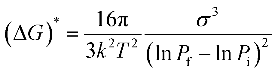 | (1) |
Table 2 shows the crystallization of some of these substrates as a comparison with references and the present work. The data is self-explanatory; crystals are obtained with a single face by slow depressurization of CO2. We believe that the scCO2 mediated method could provide commercial opportunity for a next generation environmentally benign continuous process for the preparation of unidirectional crystals.54,55 This would have huge societal impact in terms of its cost and availability as the modern era is foreseeing high demand of such organic crystals in the forthcoming advanced digital gadgets.1
| Substrate | Length (mm) | Seed crystal | CO2 (bar) | Growth ratea (m s−1) | Unidirectional (001) | Expansion technique | Reference |
|---|---|---|---|---|---|---|---|
| a ESI for calculation of growth rate. | |||||||
| Naphthalene | 0.40 | Yes | 78 | 4 × 10⁻⁷ | No (multifaced) | Slow | 21 and 22 |
| Naphthalene | 0.20 | Y | 221 | 23 | No (multifaced) | Rapid | 42 |
| Naphthalene | 0.3 | Y | 150 | 2.1 × 10⁻⁷ | Yes (multifaced) | Controlled by T, P | 29 |
| Anthracene | 2.20 | No | — | 9.1 × 10⁻⁹ | No (multifaced) | Solution | 34 |
| Anthracene | 10 | No | — | 1.15 × 10⁻⁹ | Yes (001) | Air–liquid interface | 37 |
| Anthracene | 2.00 | No | 120 | 2.8 × 10⁻⁸ | Yes (001) | Slow, precise, isothermal | Present work |
| Naphthalene | 3.00 | No | 120 | 4.22 × 10⁻⁸ | Yes (001) | –do– | –do– |
| Pyrene | 3.33 | No | 12 | 4.69 × 10⁻⁸ | Yes (001) | –do– | –do– |
5. Conclusion
In conclusion, unidirectional single crystals were obtained by precise and isothermal expansion of scCO2 solutions of naphthalene, anthracene and pyrene without using any seed crystals. Controllable size up to 3.33 mm of single crystals grown unidirectionally on the (001) plane was observed, with a crystal efficiency up to 70%. A single dominating XRD peak with an intensity of 1 × 10⁵ counts per s was observed. The growth rate obtained was on the order of 10−8 m s−1, ∼10 times faster than solvent-borne crystallization. The size of the crystal is inversely proportional to the rate of depressurization. This method provides complete material utilization and CO2 recyclability, and could be considered as a next generation environmentally benign continuous process for the commercial preparation of large-size organic crystals.Conflicts of interest
There are no conflicts to declare.Acknowledgements
The authors are highly grateful to Reliance Industries Ltd. for financial support of this work.Notes and references
- A. Saranraj, J. Thirupathy, S. S. J. Dhas, M. Jose, G. Vinitha and S. A. M. B. Dhas, Appl. Phys. B: Lasers Opt., 2018, 124, 1–9 CrossRef CAS.
- Y. Nagaoka, R. Tan, R. Li, H. Zhu, D. Eggert, Y. A. Wu, Y. Liu, Z. Wang and O. Chen, Nature, 2018, 561, 378–382 CrossRef CAS PubMed.
- J. P. Salvestrini, M. Abarkan and M. D. Fontana, Opt. Mater., 2004, 26, 449–458 CrossRef.
- T. Vetter, M. Iggland, D. R. Ochsenbein, F. S. Hänseler and M. Mazzotti, Cryst. Growth Des., 2013, 13, 4890–4905 CrossRef CAS.
- M. Arivanandhan, X. Huang, S. Uda, G. Bhagavannarayana and P. Ramasamy, J. Cryst. Growth, 2008, 310, 4587–4592 CrossRef CAS.
- A. Rollett, Science, 2018, 362, 996–997 CrossRef CAS PubMed.
- S. Sasidharan, P. C. Shyni, N. Chaudhary and V. Ramakrishnan, Sci. Rep., 2017, 7, 1–8 CrossRef CAS PubMed.
- B. R. Pamplin, in Crystal Growth – International Series in the science of solid state, Pergamon, 2nd edn, 1980, vol. 16, p. 628 Search PubMed.
- S. K. Kumar and K. P. Johnston, J. Supercrit. Fluids, 1998, 1, 15–22 CrossRef.
- E. J. Beckman, J. Supercrit. Fluids, 2004, 28, 121–191 CrossRef CAS.
- J. B. Hannay and J. Hogarth, Proc. R. Soc. London, 1879, 29, 324–326 CrossRef.
- V. J. Krukonis, Characterization and Measurement of Flavor Compounds, ACS Symposium Series, Am. Chem. Soc., 1985, ch. 11, vol. 289, pp. 154–175 Search PubMed.
- D. W. Matson, R. C. Petersen and R. D. Smith, J. Mater. Sci., 1987, 22, 1919–1928 CrossRef CAS.
- Y. Liu, P. G. Jessop, M. Cunningham, C. A. Eckert and C. L. Liotta, Science, 2006, 313, 958–960 CrossRef CAS PubMed.
- P. T. Anastus, W. Leitner and P. G. Jessop, in Green Solvents: Supercritical Solvents, Wiley VCH, 2013, vol. 4 Search PubMed.
- P. Munshi, A. D. Main, J. C. Linehan, C. C. Tai and P. G. Jessop, J. Am. Chem. Soc., 2002, 124, 7963–7971 CrossRef CAS PubMed.
- J. Jung and M. Perrut, J. Supercrit. Fluids, 2001, 20, 179–219 CrossRef CAS.
- C. Yang, M. Wang, Z. Xing, Q. Zhao, M. Wang and G. Wu, RSC Adv., 2018, 8, 20061–20067 RSC.
- M. Türk, Particle formation with supercritical fluids: challenges and limitations, Elsevier, Amsterdam, 2014 Search PubMed.
- P. G. Debenedetti, J. W. Tom, X. Kwauk and S.-D. Yeo, Fluid Phase Equilib., 1993, 82, 311–321 CrossRef CAS.
- C. Y. Tai and C. S. Cheng, Chem. Eng. Res. Des., 1997, 75, 228–232 CrossRef CAS.
- C. Y. Tai and C. S. Cheng, AIChE J., 1995, 41, 2227–2236 CrossRef CAS.
- P. Raveendran, M. A. Blatchford, M. L. Hurrey, P. S. White and S. L. Wallen, Green Chem., 2005, 7, 129–131 RSC.
- J. Pessi, I. Lassila, A. Merilainen, H. Raikkonen, E. Hæggstrom and J. Yliruusi, J. Pharm. Sci., 2016, 105, 2293–2297 CrossRef CAS PubMed.
- J. B. Felder, Hydrothermal Synthesis: A Gateway To Metastable Crystals With Unusual Properties, Doctoral dissertation, 2018 Search PubMed.
- Z. Lou, Q. Chen, Y. Zhu, Y. Zhang and J. Gao, Cryst. Growth Des., 2004, 4, 415–417 CrossRef CAS.
- V. N. Khrustalev, L. N. Nikitin, A. Y. Vasilkov and A. R. Khokhlov, Russ. Chem. Bull., 2006, 55, 576–578 CrossRef CAS.
- S. Yamaoka, M. D. S. Kumar, H. Kanda and M. Akaishi, J. Cryst. Growth, 2002, 234, 5–8 CrossRef CAS.
- H. Uchida, A. Manaka, M. Matsuoka and H. Takiyama, Cryst. Growth Des., 2004, 4, 937–942 CrossRef CAS.
- L. Glasser, A. Herráez and R. M. Hanson, J. Chem. Educ., 2009, 86, 566 CrossRef.
- P. Munshi and S. Bhaduri, Curr. Sci., 2009, 97, 63–72 CAS.
- M. Carvalho, A. Dechezlepretre and M. Glachant, in Understanding the dynamics of global value chains for solar photovoltaic technologies, Economic Research working paper No. 40, World Intellectual Property Organization, Nov. 2017, pp. 1–31 Search PubMed.
- M. Chen, L. Yan, Y. Zhao, I. Murtaza, H. Meng and W. Huang, J. Mater. Chem. C, 2018, 6, 7416–7444 RSC.
- P. Zhang, J. Deng, X. Zeng, Z. Liu, Y. Qiu, H. Zhong, Y. Fan, J. Huang, J. Zhang and K. Xu, J. Cryst. Growth, 2009, 311, 4708–4713 CrossRef CAS.
- U. Charoen-In, P. Ramasamy and P. Manyum, J. Cryst. Growth, 2013, 362, 220–226 CrossRef CAS.
- D. J. Quesnel, M. Meshii and J. B. Cohen, Mater. Sci. Eng., 1978, 36, 207–215 CrossRef.
- V. A. Postnikov and S. V. Chertopalov, Crystallogr. Rep., 2015, 60, 594–600 CrossRef CAS.
- S. Ibe, R. Ise, Y. Oaki and H. Imai, CrystEngComm, 2012, 14, 7444–7449 RSC.
- J. Ulrich and C. Strege, J. Cryst. Growth, 2002, 237–239, 2130–2135 CrossRef CAS.
- R. Brecker and W. Doring, Ann. Phys., 1935, 24, 719–752 CrossRef.
- M. T. Liang and C. M. Wang, Ind. Eng. Chem. Res., 2000, 39, 4622–4626 CrossRef CAS.
- P. G. Debenedetti, AIChE J., 1990, 36, 1289–1298 CrossRef CAS.
- R. S. Mohamed, P. G. Debenedetti and R. K. Prudhomme, AIChE J., 1989, 35, 325–328 CrossRef CAS.
- S. K. Goel and E. J. Beckman, Polym. Eng. Sci., 1994, 34, 1148–1156 CrossRef CAS.
- W. K. Burton, N. Cabrera and F. C. Frank, Philos. Trans. R. Soc., A, 1951, 243, 299–358 CrossRef.
- D. P. Woodruff, Philos. Trans. R. Soc., A, 2015, 373, 20140230 CrossRef PubMed.
- P. R. Wolde and D. Frenkel, Science, 1997, 277, 1975–1978 CrossRef PubMed.
- Handbook of Crystal Growth, Fundamentals, ed. T. Nishinaga, Elsevier, Amsterdam, 2nd edn, 2015, vol. 1A, (Thermodynamics and Kinetics), ch. 5, pp. 215–264 Search PubMed.
- N. R. Chevalier and P. Guenoun, J. Phys. Chem. Lett., 2016, 7, 2809–2813 CrossRef CAS PubMed.
- J. M. Li and J. Fang, J. Mater. Chem. C, 2017, 5, 9545–9551 RSC.
- J. M. Li, ACS Appl. Mater. Interfaces, 2017, 9, 39626–39666 CrossRef CAS PubMed.
- N. Balamurugan, A. Arulchakkaravarthi and P. Ramasamy, Phys. Status Solidi A, 2007, 204, 3502–3508 CrossRef CAS.
- R. T. Kurnik, S. J. Holla and R. C. Reld, J. Chem. Eng. Data, 1981, 26, 47–51 CrossRef CAS.
- X. Zhang, S. Heinonen and E. Levanen, RSC Adv., 2014, 4, 61137–61152 RSC.
- B. Fraboni, A. F. Morgera, Y. Greets and A. Morpurgo, Adv. Funct. Mater., 2016, 26, 2229–2232 CrossRef CAS.
Footnote |
| † Electronic supplementary information (ESI) available: Measurement of depressurized CO2. Determination of the rate of crystallization. Table S1: recycling test of anthracene. Fig. S1: pneumatic trough gas collection. Fig S2: (a) SEM image and (b) XRD of naphthalene crystals at CO2 120 bar, 45 °C, 10 mL per min. Fig. S3: (a) SEM image and (b) XRD of anthracene crystals at CO2 120 bar, 45 °C, 50 mL per min. See DOI: 10.1039/d0ra03706k |
| This journal is © The Royal Society of Chemistry 2020 |