DOI:
10.1039/D0RA03592K
(Paper)
RSC Adv., 2020,
10, 22533-22541
Highly porous, soft, and flexible vapor-phase polymerized polypyrrole–styrene–ethylene–butylene–styrene hybrid scaffold as ammonia and strain sensor†
Received
22nd April 2020
, Accepted 7th June 2020
First published on 12th June 2020
Abstract
Herein, in situ vapor-phase polymerization (VPP) of pyrrole on an oxidant-impregnated styrene–ethylene–butylene–styrene (SEBS) matrix comprising a three-dimensional sugar particle assembly was used to produce a soft and porous polypyrrole (PPy)–SEBS hybrid scaffold. Characterization of the PPy–SEBS hybrid scaffold using field-effect scanning electron microscopy, Fourier-transform infrared spectroscopy, energy-dispersive X-ray spectroscopy, and micro-computerized tomography confirmed the successful uniform and homogenous polymerization of PPy onto the SEBS matrix with a porous morphology. The performance of the hybrid scaffold of different pore sizes as an ammonia sensor under different temperature conditions was evaluated in terms of resistance change. The results showed that the PPy–SEBS scaffolds of larger pore size had higher resistance changes under lower temperature conditions when ammonia (NH3) gas was introduced compared to those observed for smaller pore sizes under higher temperature conditions. These scaffolds showed excellent repeatability and reversibility in detecting NH3 gas with fast response and recovery times of 30 s and 10–15 min, respectively. Moreover, the larger pore size scaffolds polymerized for a longer time possessed a remarkable ability to be applied as strain sensors. These kinds of novel, soft, and porous conductive polymer composite materials produced by VPP will have huge practical applications in monitoring other toxic and non-toxic gases.
1. Introduction
Intrinsically conducting polymers (CPs) have gained tremendous attention as smart materials since their discovery, as they are flexible, lightweight, electrochemically stable, biocompatible and easily processable, and can conduct electricity.1,2 Due to these excellent properties, CPs have been extensively exploited in fuel cells,3,4 organic transistors,5,6 organic light emitting diodes,7,8 sensors and actuators,8,9 and electrochromic devices.10,11
Among the CPs, polypyrrole (PPy) alone or in a composite with other materials is most commonly used for the fabrication of electronic devices and sensors due to excellent conductivity and processability.12–14 There are several studies using PPy as sensors for gases, humidity, chemicals, temperature, and strain.15,16 Likewise, hybrid composites of PPy with other organic or inorganic materials have also been used to improve the electrical properties of the material for gas and chemical sensing applications.17–19 Joshi et al. studied the selective response of PPy thin films towards NH3 and found that the response linearly increases with the NH3 concentration.20 Similarly, in another study, an organic–inorganic hybrid of PPy and MoO3((PPy)xMoO3) showed a unique sensitive and selective response to volatile organic compounds like formaldehyde and acetaldehyde.21 Likewise, in situ chemical polymerization of PPy/ZnSnO3 nanocomposites exhibited a greater response to NH3 gas compared to pristine PPy.22 This improvement in sensor performance was believed to be caused by the uniform distribution of loose and porous PPy coatings providing the composites with a higher surface area to volume ratio and contributing to the efficient gas diffusion process. Moreover, PPy thin films produced by chemical polymerization demonstrated opposite responses towards ammonia and lactic acid, as ammonia favored a reduction reaction, whereas lactic acid favored an oxidation reaction of PPy.23 However, the drawbacks of these materials include inferior electrical and physiochemical properties and poor chemical and electrical stability.
Vapor-phase polymerization (VPP) is a well-established technique for fabricating CPs in which the vapor of monomers are exposed to the oxidant-coated substrates in order to form a uniform, thin, and highly conducting layer of CPs.24–26 Similarly, the simultaneous VPP of organic–organic or organic–inorganic materials can generate hybrid conductive films exhibiting excellent electrical and physiochemical properties.27–31 One of the prime interests of our research group is to produce robust, highly conductive, and stable CPs and composites using VPP for application in bioelectronic devices and strain sensors. There are numerous studies in which the VPP technique was used to prepare CPs (mainly PPy and poly (3,4-ethylenedioxythiophene) (PEDOT)) and their hybrid composites with enhanced electromechanical properties and biocompatibility suitable for fabricating various electronic devices and sensors.28,30–34
In this study, we further extended our research in fabricating a novel hybrid scaffold material using a VPP-based pyrrole as the active element and styrene–ethylene–butylene–styrene (SEBS) as the main matrix material. The surface morphology and chemical composition of the scaffold were investigated to confirm the formation of a soft, flexible, and homogeneous hybrid between PPy and SEBS, signifying the uniform and stable polymerization of PPy on the surface as well as on the entire section of the scaffold. We show that these scaffolds of various pore sizes with different VPP times possess a remarkable ability to detect NH3 gas sensitively as well as their application as strain sensors. To the best of our knowledge, this is the first ever PPy–SEBS hybrid scaffold synthesized using VPP that was used as an NH3 gas and strain sensor.
2. Experimental section
2.1. Materials
The copolymer SEBS (styrene ratio = 30 wt%, specific gravity = 0.91 g mL−1, Tg = −42 °C, hardness = 69 Shore A, tensile strength = 31 MPa, elongation at break = 500%, 300% modulus = 4.8 MPa, Kraton General, G1652) was used as the scaffold material, iron(III) p-toluenesulfonate (FTS, Sigma-Aldrich) was used as an oxidant and dopant, Py (Acros Organics) was used as the monomer for PPy, tetrahydrofuran (THF, Samchun Pure Chemical Co., Seoul, Korea) was used to dissolve the oxidant and scaffold material, three kinds of sugar with different particle sizes (Colorcon Asia Pacific Pte) were used to form the different pore sizes in each of the scaffolds, and an NH3 solution (Junsei Chemical Co., Japan) was used to test the response of the scaffolds. All the chemicals were used without further purification.
2.2. Methods
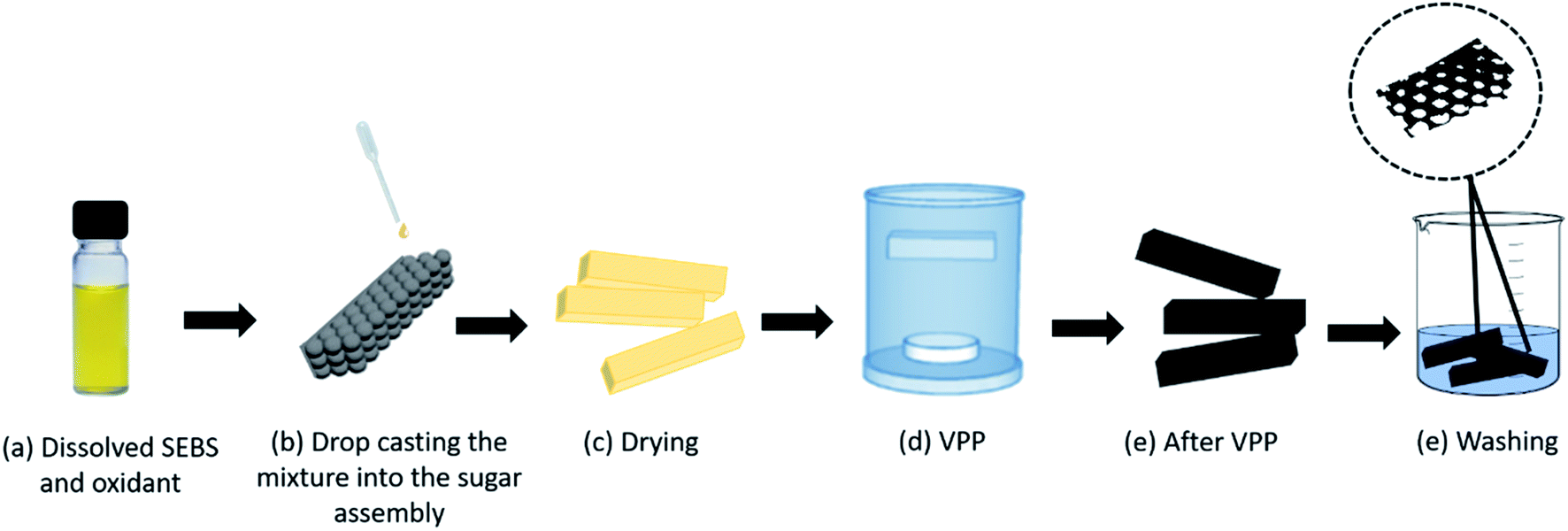
2.2.1. Fabrication of the PPy–SEBS hybrid scaffold. The stepwise VPP of the PPy–SEBS hybrid scaffold material is shown in Scheme 1. 10 wt% SEBS was dissolved in THF solvent for 4 h under continuous stirring at room temperature. The oxidant FTS with a 10 wt% concentration was poured into the solution and stirred at room temperature for 2 h. Three kinds of sugar particles with different pore sizes were poured into the respective silicon mold (dimensions: 4 cm × 1 cm × 1 cm) to form small, medium, and large pore scaffolds. Drops of the SEBS–FTS mixture were then poured onto the sugar-coated assembly in order to moisten and preserve the intactness of the assembly.
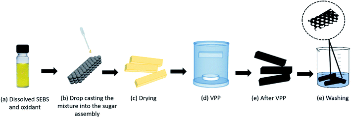 |
| | Scheme 1 Schematic representation of the vapor-phase polymerization (VPP) of polypyrrole (PPy)–styrene–ethylene–butylene–styrene (SEBS) onto a sugar-coated silicon mold assembly in order to form a hybrid scaffold material. | |
After drying the whole assembly at room temperature for a day, it was then transferred to a small mesh pocket to hold it in place and then placed in the middle of the VPP chamber. The Py monomer was placed at the bottom of the chamber, the internal temperature of which was maintained at room temperature. After 1 h VPP, the PPy–SEBS-coated sugar particle assembly was rinsed with deionized (DI) water to fully remove unreacted reagents and was subsequently immersed in distilled water for 2 days at room temperature to dissolve the sugar particles. The PPy–SEBS scaffold was then dried in ambient air for 24 h to form a porous scaffold with different pore sizes.
2.2.2. Surface characterization of the PPy–SEBS hybrid scaffold. Surface morphologies and elemental distributions of the porous scaffold were obtained by using field effect scanning electron microscopy (FE-SEM; MIRA LMH, TESCAN) and energy dispersive X-ray spectroscopy (EDS; Bruker AXS XFlash detector 5010), respectively. Twisting, stretching, and bending tests were conducted by using a home-made multi-purpose flexibility test machine (IPEN Co., Korea) to confirm the flexibility and softness of the PPy–SEBS hybrid scaffold. Likewise, micro computerized tomography (micro-CT; SkyScan 1272, Bruker AXS), a non-destructive method for visualizing the object interior, was used to image and characterize the pores of the hybrid scaffold. 3D model reconstruction and analysis were performed using software supplied by the micro-CT manufacturer (NRecon, SkyScan), in which its X-ray source was operated at a voltage of 50 kV and a current of 200 mA. Moreover, to confirm the chemical structure of the polypyrrole, Fourier transform infrared (FTIR) spectroscopy was conducted.
2.2.3. Performance of the PPy–SEBS hybrid scaffold as an NH3 gas sensor. The custom-built experimental set up used to evaluate the performance of the PPy–SEBS hybrid scaffold as an NH3 sensor is shown in ESI, Fig. S-1(A).† To measure the NH3 gas response, the resistance of the PPy–SEBS sensors was measured in ambient air and in the NH3 atmosphere. For resistance measurement, two alligator clips were clipped on the PPy–SEBS hybrid scaffold separated by 2 cm. The PPy–SEBS sensor was enclosed in an airtight gas chamber that had a volume of 1 L, into which the NH3 was injected through a micropipette. Then, 30 μL of NH3 was injected into the chamber every 15 min. Measurements were carried out at 20 °C, 40 °C, and 60 °C. An oil bath was included in the set up to control the temperature conditions. Resistance variation was measured by an inductor/capacitor/resistor (LCR) meter (GW Instek, LCR-6100). The sensor response was calculated using eqn (1):| | |
Sensor response = (R − Ro)/Ro
| (1) |
where Ro indicates initial resistance, and R indicates resistance upon ammonia exposure.
2.2.4. Performance of the PPy–SEBS hybrid scaffold as a strain sensor. Strain sensing measurements were conducted using a multi-purpose flexibility test machine that can stretch and release a sample up to a 33.33% extension (ESI, Fig. S-1(B)†). One stretch and one release of the sample is considered one cycle. For this experiment, 50 cycles were performed in 4 min on each sample to observe its behavior as a strain sensor. The sample was connected to the LCR meter, and its resistance variation was recorded. All small, medium, and large pore scaffolds were subjected to strain testing. Moreover, the PPy–SEBS scaffolds prepared at different VPP times (1 h 30 min, 2 h, and 4 h) were evaluated as strain sensors.
3. Results and discussion
3.1. Surface characterization of the PPy–SEBS hybrid scaffold
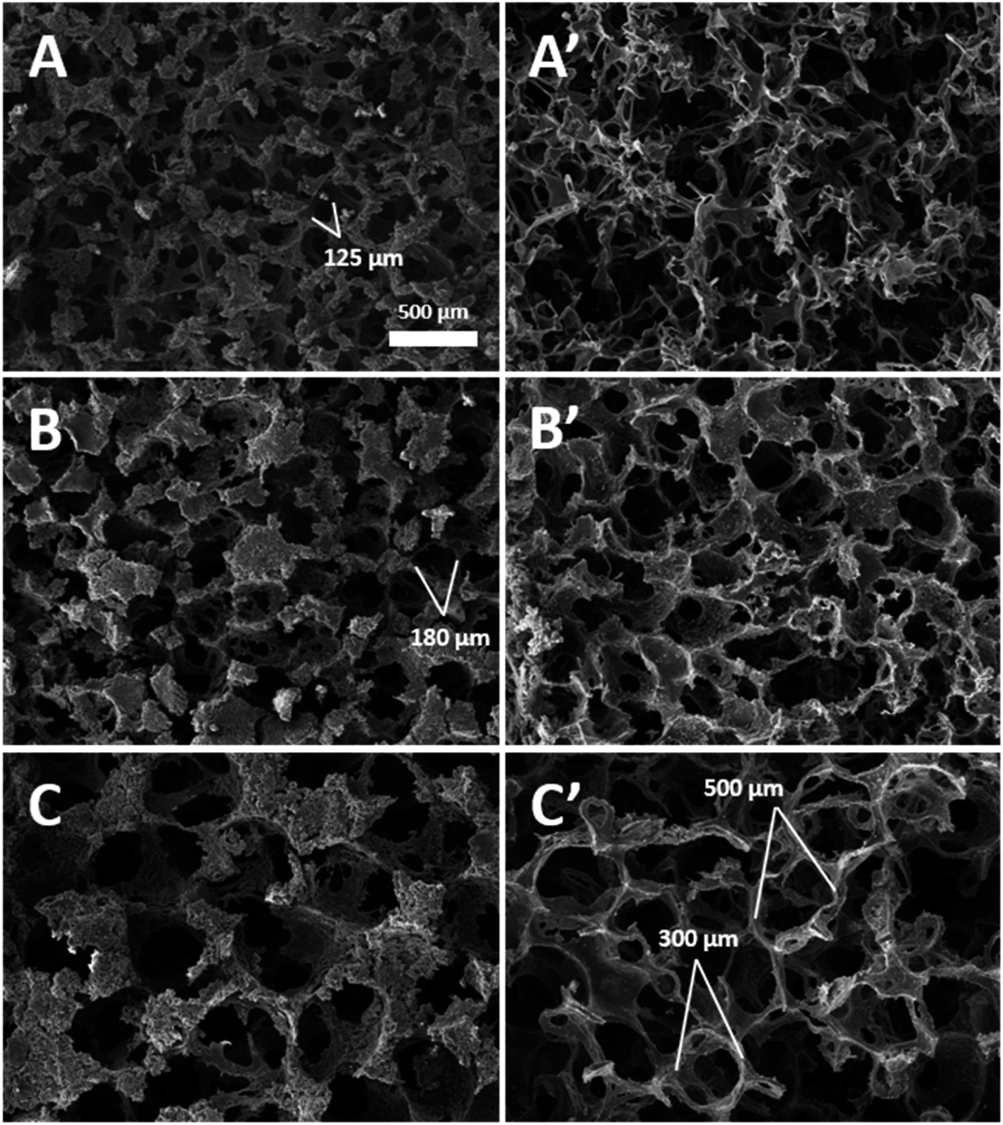
SEM was used to investigate the surface properties of all three (small, medium, and large) sizes of PPy–SEBS hybrid scaffolds (Fig. 1). The top view and cross sections of the PPy–SEBS hybrid scaffolds were analyzed in detail. These images clearly showed the PPy–SEBS scaffolds that were fabricated using small, medium, and large sugar particles (ESI, Fig. S-2†). These kinds of porous structures are believed to provide fine pathways for electron transfer in the gas sensing process and are expected to be advantageous for gas sensing applications due to the availability of diffusion channels inside the polymeric network.35 Additionally, a porous and loose structure surface morphology provides a higher surface area to volume ratio, which significantly contributes to the gas diffusion process, therefore improving the gas sensing properties.36,37
 |
| | Fig. 1 SEM images of the (A) small, (B) medium, and (C) large-pore-sized PPy–SEBS hybrid scaffolds obtained by removing sugar particles after VPP. Left panel shows the surface and right panel shows the cross section of the scaffolds. | |
Fig. 2 shows the photographic images during (A) twisting, (B) stretching, and (C) bending. The PPy–SEBS hybrid scaffold withstood multiple times of stretching up to 100% and bending up to 50% at a speed of 0.05 count per s. Moreover, it also withstood multiple twisting at a rate of 0.3 count per s. The video files showing the twisting, stretching and bending of the PPy–SEBS hybrid scaffold are attached in the ESI Movie† files named twisting, stretching, and bending respectively. The PPy–SEBS hybrid scaffold was not deformed during the process and thus is proven to be a soft and flexible composite.
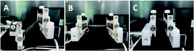 |
| | Fig. 2 Photographs during the (A) twisting, (B) stretching, and (C) bending of the PPy–SEBS hybrid scaffold. | |
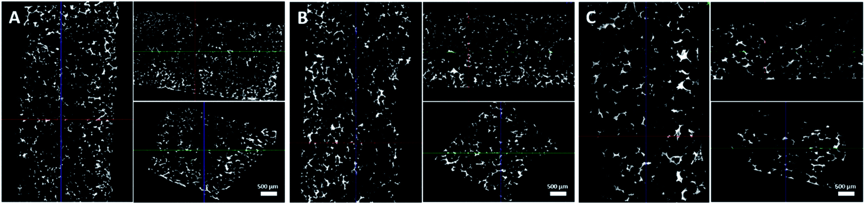
The internal skeletal structures of the PPy–SEBS hybrid scaffolds were imaged by micro-CT (Fig. 3), and the pore size distributions of all three pores are shown in Fig. 4. The definition of axis for micro-CT images is displayed in (ESI, Fig. S-3†). All types of PPy–SEBS hybrid scaffolds were well developed and showed open interconnected pores in three dimensions as shown in Fig. 3. The obtained scaffolds showed an excellent porosity of 95.8%, 96.0%, and 97.6% for small, medium, and large pores, respectively. The scaffold pore diameter was smaller than that of the sugar particles because of the formation of shriveled hollow shell structures after the sugar porogen removal, which indicated that the produced scaffold exhibited the elastomeric properties of SEBS. The average pore diameter of the small pore scaffolds was ∼115 μm and 200 μm, while the average pore diameter of the medium pore scaffolds can be described as a bimodal of ∼160 μm and ∼370 μm, and the large pore scaffolds had a bimodal pore diameter of ∼250 μm and 500 μm, respectively. These open and interconnected pores of variable sizes enable the rapid diffusion of gases into the network.38
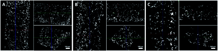 |
| | Fig. 3 Exploitation of the xyz-separable characteristics of the (A) small, (B) medium, and (C) large-pore-sized scaffolds. | |
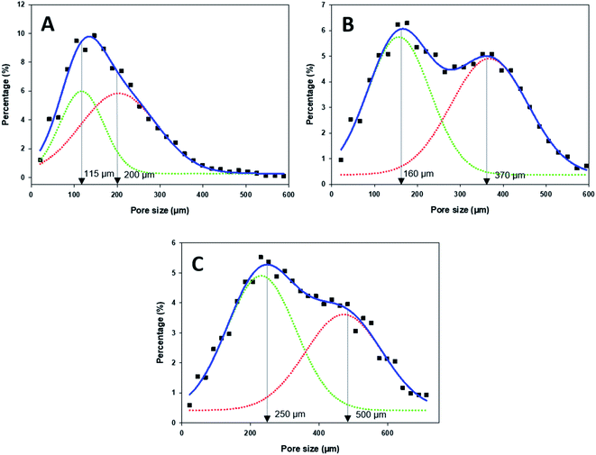 |
| | Fig. 4 Pore size distribution of the (A) small-, (B) medium-, and (c) large-pore-sized PPy–SEBS hybrid scaffold. | |
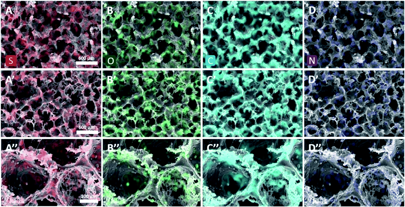
To verify that VPP resulted in the uniform formation of PPy in the SEBS matrix, the elemental distributions of major chemical elements in the scaffold were investigated using EDS. Fig. 5 shows that sulfur, oxygen, carbon, and nitrogen were well distributed in all scaffold surfaces and cross sections, which implied that the Py monomer could penetrate the SEBS matrix during VPP, with FTS-initiated in situ polymerization resulting in hybridization with the SEBS matrix.34,39 The scaffold material consisted of 6.02 wt% of nitrogen after VPP, which implies that a considerable amount of PPy was generated.40 Therefore, a novel method of fabricating a PPy–SEBS hybrid composite material was achieved through in situ VPP. The results also confirmed that the uniform coating of PPy was not only achieved on the surface but also on the inner side of the SEBS matrix owing to the effective penetration and diffusion of the Py monomer during VPP.41
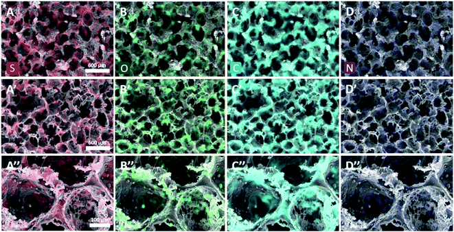 |
| | Fig. 5 EDS elemental mappings of (A) sulfur (red), (B) oxygen (green), (C) carbon (blue), and (D) nitrogen (purple). Top panel shows the top view, middle panel shows the cross-sections, and bottom panel shows the enlarged images of the medium pore scaffolds. | |
The chemical structure of PPy was confirmed by using FTIR spectroscopy as shown in Fig. 6. A SEBS–THF solution was measured as a control spectrum to elucidate the formation of uniform PPy coatings in the SEBS matrix after VPP. The spectrum of the PPy–SEBS scaffold recorded in the range of 500–4000 cm−1 waves showed a characteristic peak at 702 cm−1, which corresponds to C–H wagging. The peaks at 1464 cm−1, 1547 cm−1, and 1645 cm−1 represent the vibration of the pyrrole ring and the ring stretching mode of pyrrole.42,43 Similarly, the peak observed at 2927 cm−1 corresponds to the absorbance band of the CH2 groups. Moreover, the broad peak that appeared at 3425 cm−1 is attributed to the stretching of N–H and C–H bonds.43 All these characteristic peaks observed during FTIR analysis further support our claim of the uniform VPP deposition of PPy on the outer as well as inner surfaces of the SEBS matrix, making PPy–SEBS a flexible and conducting hybrid material.
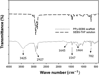 |
| | Fig. 6 FTIR spectra of the PPy–SEBS scaffold and SEBS–THF solution showing the uniform VPP deposition of PPy on the SEBS matrix. | |
3.2. Performance of the PPy–SEBS hybrid scaffold as an NH3 sensor
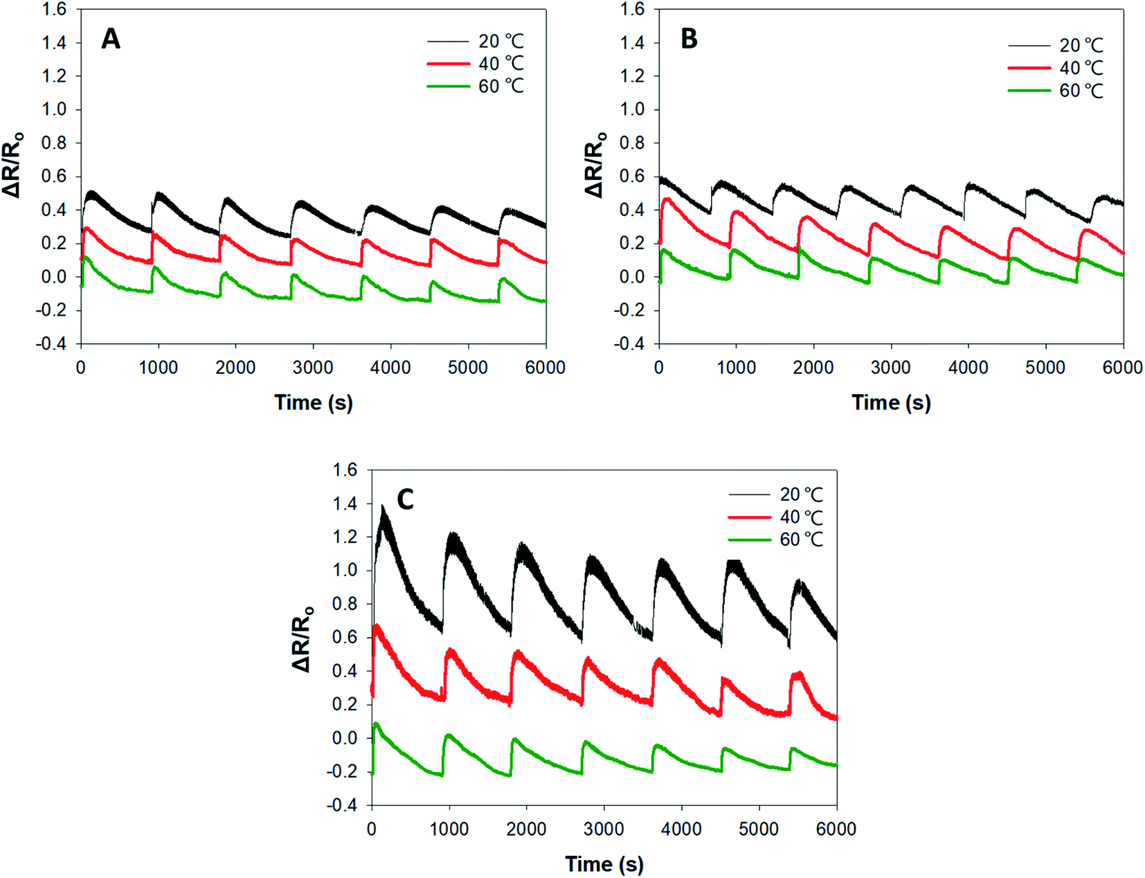
The responses of PPy–SEBS hybrid scaffolds of various pore sizes to NH3 gas at different operating temperatures (20 °C, 40 °C, and 60 °C) are shown in Fig. 7. It was observed that all PPy–SEBS hybrid scaffold sizes performed best at a lower temperature (20 °C). This is because the polymers are liable to degrade more in the elastomeric phase due to its low Tg because lower temperature promotes permeability, leading to oxygen diffusion and thus increasing the response of the sensor.44,45
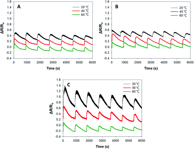 |
| | Fig. 7 Response of the (A) small-, (B) medium-, and (C) large-pore-sized PPy–SEBS hybrid scaffold to NH3 gas at different operating temperatures. | |
Moreover, the responses of small-, medium-, and large-pore-sized PPy–SEBS hybrid scaffolds at the lower temperature of 20 °C were also compared; the large-pore-sized scaffold exhibited the highest response to NH3. The sensing ability of the material is highly dependent on the porosity of the material, so the large-pore-sized scaffold enabled the easy diffusion of gas molecules into all areas.36 The concentration of NH3 used was 750 ppm. As a control measurement, the sensor was tested for its response to H2O as well. The results showed that the sensor is not responsive to water (ESI, Fig. S-4†) because water is a neutral compound (pH ∼ 7) so there is no interaction to the PPy as compared to the reduction of PPy upon the introduction of NH3.
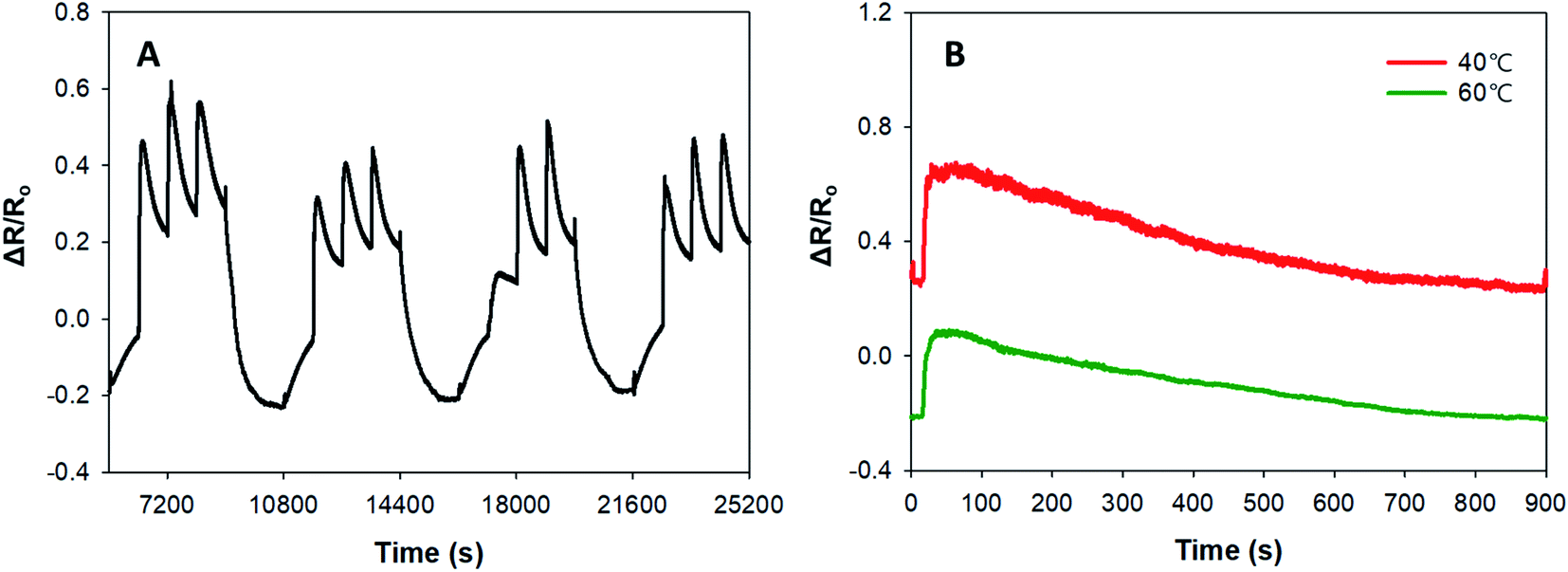
In addition to the sensitivity of PPy–SEBS hybrid scaffold sensors in detecting NH3 gas, we also demonstrated the reversibility and repeatability of our sensors by purging nitrogen (N2) gas at 50 °C. Fig. 8 (A) shows the reversibility and repeatability of the PPy–SEBS hybrid scaffold as an NH3 gas sensor for four cycles. For each cycle, 30 μL of NH3 was introduced every 15 min three times and purged with N2 for 30 min at 50 °C to reset the sensor. Purging with N2 gas for 30 min at 50 °C helped in resetting the increased resistance values to the baseline between each cycle. When the NH3 gas was introduced, an increase in electrical resistance was observed in all four cycles. The increase in electrical resistance corresponding to the decrease in current in the PPy–SEBS scaffold material is due to the electron donating nature of NH3, as shown in eqn (2a) and (b):20,46,47
| | |
PPy+ + NH3 → PPy0 + NH3+ adsorption reaction
| (2a) |
| | |
PPy0 + NH3 → PPy+ + NH3↑desorption reaction
| (2b) |
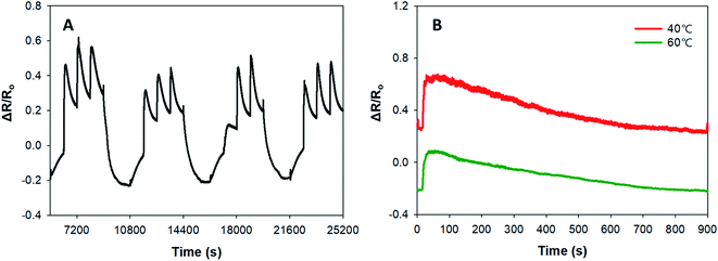 |
| | Fig. 8 (A) Repeatability and reversibility of the PPy–SEBS hybrid scaffold material in detecting NH3 gas, (B) response and recovery time of the PPy–SEBS hybrid scaffold. | |
Bhat et al. showed a similar phenomenon of decrease in current upon exposure to NH3 gas due to the lone pair of electrons in the nitrogen, which can be easily donated to the initially oxidized PPy.47 These lone electron pairs neutralize the PPy cation, which is positively charged; therefore, the number of carriers decreases, resulting in a decrease in current, i.e., an increase in electrical resistance, which was observed in this case.46 The other important parameters used to characterize a sensor are its response and recovery time (Fig. 8(B)). The PPy–SEBS hybrid scaffolds showed an excellent response time of approximately 30 s in detecting NH3 for all samples tested, and the sensors could recover after exposure to N2 for 10–15 min. The response and recovery times are dependent on the rate of adsorption and desorption.48
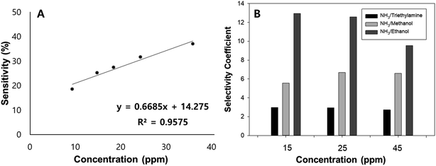
The response of the sensor towards low concentrations of NH3 was further investigated and was found to have a good linearity with a coefficient of determination equal to 0.9575 (Fig. 9(A)). Moreover, its selectivity towards other reducing gases such as ethanol, methanol, and triethylamine was studied. In order to study the selective behavior of the sensor, gas sensing measurements were conducted at various concentrations (15, 25, and 45 ppm). Its selectivity coefficient, defined as the ratio of the response of the sensor towards NH3 and other reducing gases, ranges from 3 to 13. The large value of sensitivity coefficients signifies the sensor's excellent performance to determine NH3 gas. The bar chart (Fig. 9(B)) shows the selectivity coefficient values of the sensor as a function of detected chemical concentration. Usually, the coefficient of selectivity for sensors must be more than 5.48
 |
| | Fig. 9 (A) Linear response range of the PPy–SEBS hybrid scaffold, (B) selectivity of NH3 sensor towards other reducing gases. | |
3.3. Mechanism on the NH3 sensing using PPy
The mechanism of NH3 sensing using CPs, like PPy, is essentially due to the irreversible reaction causing the reduction of PPy.49 The change in the conductivity of the polymer material is caused by the reduction of the polymer film, therefore making it a suitable material for resistometric ammonia detection. PPy is a p-type material, and when it reacts with reducing gases like NH3, there is a reduction in charge carrier density. Since the majority of carrier (hole) density decreases because of the electron donating nature of these gas, the conductivity of the polymer material decreases, resulting in an increase in resistance.23,48 The electrical conductivity equation for conducting polymers is analogous with the semiconductor one as shown in eqn (3):where σ is the electrical conductivity of the material, e is the electric charge, n is the electron density, μn is the mobility of the electron, p is the hole density, and μp is the hole mobility.
As the number of holes is greater than the number of electrons in a p-type semiconductor, (p ≫ n), then σ = epμp. Therefore, when PPy is exposed to reducing gases such as NH3, it gains electrons, thus, the number of holes will be reduced, which eventually decreases the electrical conductivity.50,51
3.4. Performance of the PPy–SEBS hybrid scaffolds as strain sensors
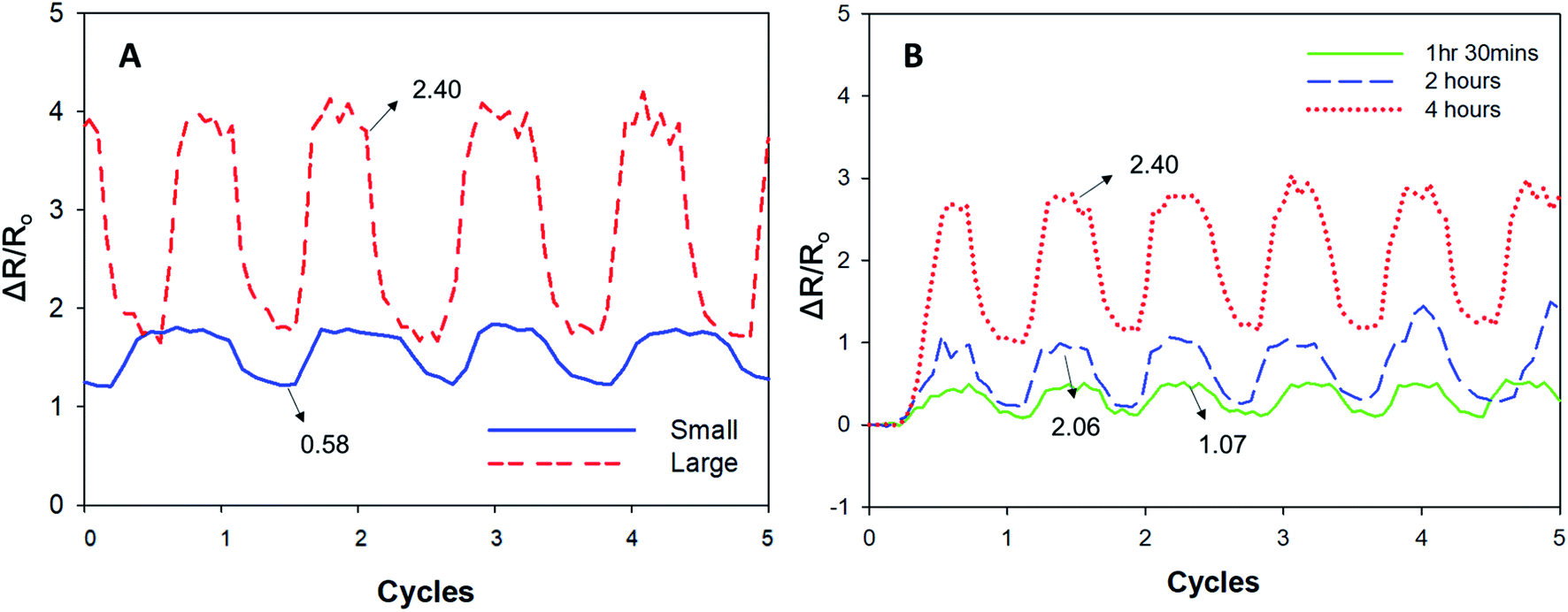
We also evaluated the PPy–SEBS hybrid scaffolds of different pore sizes as strain sensors by using the ratio of relative resistance change, ΔR/Ro, where Ro is the initial electrical resistance and ΔR is the resistance change for a given cycle. Our results indicated that the ΔR/Ro value was higher for large pore sizes compared to the small-pore-sized scaffolds. The sensitivity of these strain sensors was also evaluated using the gauge factor, which is defined as ΔR/εRo, where ε is the strain applied, and which represents the sensitivity of the sensors. Fig. 10(A) shows that the gauge factor of large pore size scaffolds increased to 2.40 compared to the 0.58 shown in small pore size scaffolds that were also polymerized for 4 h. The strain sensitivity of the scaffolds increased with increasing pore size because a larger pore size scaffold is more easily cracked during the strain process, which makes the resistance increase in the scaffolds more significant and the sensitivity greater.52 Moreover, the strain sensitivity of large pore size scaffolds synthesized at different VPP times were also examined in detail (Fig. 10(B)). The gauge factors of the PPy–SEBS hybrid scaffolds polymerized for 1 h 30 min, 2 h, and 4 h were 1.07, 2.06, and 2.40, respectively. The results showed that the gauge factor of the scaffold increased with greater VPP time, as this allowed for the optimum polymerization of the PPy–SEBS hybrid scaffolds, resulting in improved performance as strain sensors.
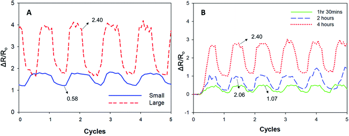 |
| | Fig. 10 Performance of the PPy–SEBS hybrid scaffolds of (A) different pore sizes and (B) different VPP times as strain sensors. | |
4. Conclusion
A soft and porous PPy–SEBS hybrid scaffold material was synthesized by the hybridization of PPy with SEBS using in situ VPP. The successful polymerization and uniform distribution of porous PPy on the SEBS matrix that is suitable for gas and strain sensors was confirmed using SEM, EDS, micro-CT, and FTIR. From the NH3 sensing study, it was observed that the large-pore-sized PPy–SEBS scaffolds exhibited a higher sensitivity to NH3 at a lower temperature of 20 °C, as it enabled the easy diffusion of gas molecules into all areas of the scaffold material. Likewise, these scaffolds showed excellent repeatability and reversibility in detecting NH3 gas with fast response and recovery times of 30 s and 10–15 min, respectively. Moreover, the larger pore size scaffolds that were polymerized for a longer time possessed a remarkable application ability as strain sensors. This work demonstrates, for the first time, that VPP synthesized PPy–SEBS hybrid scaffold materials tuned to optimum conditions can be used as high performing NH3 and strain sensors. Moreover, these materials can operate even at higher temperatures of up to 60 °C, which makes them promising candidates for device applications. These results set a precedent for the use of such CP hybrid composite materials to detect other gases and chemicals, which could form the core of smart real-time/point-of-care devices for medical, food, agricultural, and environmental applications.
Conflicts of interest
There are no conflicts to declare.
Acknowledgements
This research was supported by the Basic Science Research Program through the National Research Foundation of Korea (NRF), funded by the Ministry of Education (NRF-2019R1I1A3A01054826).
References
- M. Audenaert, G. Gusman and R. Deltour, Phys. Rev. B: Condens. Matter Mater. Phys., 1981, 24, 7380–7382 CrossRef CAS.
- A. J. Hackett, J. Malmström and J. Travas-Sejdic, Prog. Polym. Sci., 2017, 70, 18–33 CrossRef CAS.
- B. Kolodziejczyk, O. Winther-Jensen, D. R. MacFarlane and B. Winther-Jensen, J. Mater. Chem., 2012, 22, 10821–10826 RSC.
- T. Kuwahara, H. Ohta, M. Kondo and M. Shimomura, Bioelectrochemistry, 2008, 74, 66–72 CrossRef CAS PubMed.
- J. Liu, M. Agarwal and K. Varahramyan, Sens. Actuators, B, 2008, 135, 195–199 CrossRef CAS.
- Z. Zhu, J. T. Mabeck, C. Zhu, N. C. Cady, A. Batt and G. G. Malliaras, Mater. Sci., 2004, 1556–1557 CAS.
- W. H. Kim, A. J. Mäkinen, N. Nikolov, R. Shashidhar, H. Kim and Z. H. Kafafi, Appl. Phys. Lett., 2002, 80, 3844–3846 CrossRef CAS.
- H. Peng, L. Zhang, C. Soeller and J. Travas-Sejdic, Biomaterials, 2009, 30, 2132–2148 CrossRef CAS PubMed.
- R. Khadka, N. Aydemir, A. Kesküla, T. Tamm, J. Travas-Sejdic and R. Kiefer, Synth. Met., 2017, 232, 1–7 CrossRef CAS.
- M. V. Fabretto, D. R. Evans, M. Mueller, K. Zuber, P. Hojati-Talemi, R. D. Short, G. G. Wallace and P. J. Murphy, Chem. Mater., 2012, 24, 3998–4003 CrossRef CAS.
- K. Gurunathan, A. V. Murugan, R. Marimuthu, U. P. Mulik and D. P. Amalnerkar, Mater. Chem. Phys., 1999, 61, 173–191 CrossRef CAS.
- D. W. Hatchett and M. Josowicz, Chem. Rev., 2008, 108, 746–769 CrossRef CAS PubMed.
- H. Liu, Q. Li, S. Zhang, R. Yin, X. Liu, Y. He, K. Dai, C. Shan, J. Guo, C. Liu, C. Shen, X. Wang, N. Wang, Z. Wang, R. Wei and Z. Guo, J. Mater. Chem. C, 2018, 6, 12121–12141 RSC.
- M. H. Naveen, N. G. Gurudatt and Y. B. Shim, Applied Materials Today, 2017, 9, 419–433 CrossRef.
- D. Tyler McQuade, A. E. Pullen and T. M. Swager, Chem. Rev., 2000, 100, 2537–2574 CrossRef PubMed.
- S. Wang, Y. Kang, L. Wang, H. Zhang, Y. Wang and Y. Wang, Sens. Actuators, B, 2013, 182, 467–481 CrossRef CAS.
- N. Ballav and M. Biswas, Mater. Lett., 2006, 60, 514–517 CrossRef CAS.
- N. O. Savage, Sens. Actuators, B, 2009, 143, 6–11 CrossRef.
- R. P. Tandon, M. R. Tripathy, A. K. Arora and S. Hotchandani, Sens. Actuators, B, 2006, 114, 768–773 CrossRef CAS.
- A. Joshi, S. A. Gangal and S. K. Gupta, Sens. Actuators, B, 2011, 156, 938–942 CrossRef CAS.
- K. Hosono, I. Matsubara, N. Murayama, S. Woosuck and N. Izu, Chem. Mater., 2005, 17, 349–354 CrossRef CAS.
- P. Song, Q. Wang and Z. Yang, Mater. Lett., 2011, 65, 430–432 CrossRef CAS.
- A. Jafari and A. Amini, Mater. Lett., 2019, 236, 175–178 CrossRef CAS.
- R. Brooke, M. Fabretto, P. Hojati-Talemi, P. Murphy and D. Evans, Polymer, 2014, 55, 3458–3460 CrossRef CAS.
- A. T. Lawal and G. G. Wallace, Talanta, 2014, 119, 133–143 CrossRef CAS PubMed.
- B. Winther-Jensen and K. West, Macromolecules, 2004, 37, 4538–4543 CrossRef CAS.
- J. S. Choi, J. S. Park, B. Kim, B. T. Lee and J. H. Yim, Polymer, 2017, 124, 95–100 CrossRef CAS.
- Y. H. Han, J. Travas-Sejdic, B. Wright and J. H. Yim, Macromol. Chem. Phys., 2011, 212, 521–530 CrossRef CAS.
- R. Khadka and J. H. Yim, Macromol. Res., 2015, 23, 559–565 CrossRef CAS.
- J. S. Park, B. Kim, B. T. Lee, J. S. Choi and J. H. Yim, J. Mater. Chem. B, 2018, 6, 4082–4088 RSC.
- J. H. Yim, Compos. Sci. Technol., 2013, 86, 45–51 CrossRef CAS.
- Y. S. Ko and J. H. Yim, Polymer, 2016, 93, 167–173 CrossRef CAS.
- J. Ahn, S. Yoon, S. G. Jung, J. H. Yim and K. Y. Cho, J. Mater. Chem. A, 2017, 5, 21214–21222 RSC.
- P. M. Losaria and J. H. Yim, J. Ind. Eng. Chem., 2019, 74, 108–117 CrossRef CAS.
- R. Song, Z. Wang, X. Zhou, L. Huang and L. Chi, Chempluschem, 2019, 84, 1222–1234 CrossRef CAS PubMed.
- H. Ji, W. Zeng and Y. Li, Nanoscale, 2019, 11, 22664–22684 RSC.
- Kenry and C. T. Lim, Prog. Polym. Sci., 2017, 70, 1–17 CrossRef CAS.
- Q. L. Loh and C. Choong, Tissue Eng., Part B, 2013, 19, 485–502 CrossRef CAS PubMed.
- A. Laforgue and L. Robitaille, Chem. Mater., 2010, 22, 2474–2480 CrossRef CAS.
- K. Yu, N. Kumar, J. Roine, M. Pesonen and A. Ivaska, RSC Adv., 2014, 4, 33120–33126 RSC.
- A. Kaynak, S. S. Najar and R. C. Foitzik, Synth. Met., 2008, 158, 1–5 CrossRef CAS.
- F. N. Ajjan, M. J. Jafari, T. Rębiś, T. Ederth and O. Inganäs, J. Mater. Chem. A, 2015, 3, 12927–12937 RSC.
- Y. Matsumoto and K. Honma, J. Chem. Phys., 2007, 127, 183410 Search PubMed.
- S. P. Lyu and D. Untereker, Int. J. Mol. Sci., 2009, 10, 4033–4065 CrossRef CAS PubMed.
- X. D. Wang and O. S. Wolfbeis, Chem. Soc. Rev., 2014, 43, 3666–3761 RSC.
- H. Bai and G. Shi, Sensors, 2007, 7, 267–307 CrossRef CAS.
- N. V. Bhat, A. P. Gadre and V. A. Bambole, J. Appl. Polym. Sci., 2001, 80, 2511–2517 CrossRef CAS.
- S. T. Navale, A. T. Mane, M. A. Chougule, R. D. Sakhare, S. R. Nalage and V. B. Patil, Synth. Met., 2014, 189, 94–99 CrossRef CAS.
- S. Carquigny, J. B. Sanchez, F. Berger, B. Lakard and F. Lallemand, Talanta, 2009, 78, 199–206 CrossRef CAS PubMed.
- D. N. Huyen, N. T. Tung, T. D. Vinh and N. D. Thien, Sensors, 2012, 12, 7965–7974 CrossRef CAS PubMed.
- P. Liu, S. Wu, Y. Zhang, H. Zhang and X. Qin, Nanomaterials, 2016, 6, 121 CrossRef PubMed.
- J. Wang, W. Zhang, Q. Yin, B. Yin and H. Jia, J. Mater. Sci.: Mater. Electron., 2020, 31, 125–133 CrossRef CAS.
Footnote |
| † Electronic supplementary information (ESI) available. See DOI: 10.1039/d0ra03592k |
|
| This journal is © The Royal Society of Chemistry 2020 |
Click here to see how this site uses Cookies. View our privacy policy here. 
 Open Access Article
 This Open Access Article is licensed under a Creative Commons Attribution-Non Commercial 3.0 Unported Licence
 *b and
Jin-Heong Yim
*b and
Jin-Heong Yim