 Open Access Article
High crystallinity Sn crystals on Ni foam: an ideal bimetallic catalyst for the electroreduction of carbon dioxide to syngas†
Ying Zhao a,
Dongyue Sua,
Wentao Dongc,
Xiaoyang Xua,
Xiangjing Zhang*ab and
Yongqi Hu*a
aSchool of Chemical and Pharmaceutical Engineering, Hebei University of Science and Technology, Shijiazhuang, Hebei 050018, P. R. China. E-mail: hebustzhangxj@163.com; huyq2000@126.com
bKey Laboratory of Medicinal Chemical of Hebei Province, Shijiazhuang, Hebei 050018, P. R. China
cInstitute for Development of Energy for African Sustainability (IDEAS), University of South Africa, Florida 1710, South Africa
First published on 23rd October 2020
Abstract
The investigation of highly efficient catalysts for the electrochemical reduction of carbon dioxide (ER-CO2) is the most critical challenge to commercialize conversion and utilization of CO2. Herein we propose a new and very promising catalyst, high crystallinity Sn crystals on Ni foam (Sn@f-Ni), for the electroreduction reaction of CO2 in potassium bicarbonate aqueous solution. The catalyst is fabricated in situ on a pretreated Ni foam substrate through a galvanostatic electrodeposition strategy. SEM and XRD demonstrate that high crystallinity Sn crystals, with an average size of 2–3 μm, evenly dispersed on the Ni foam support can be reproducibly obtained. Electrochemical measurements demonstrate that the Sn@f-Ni electrode at the deposition current of 15 mA exhibits superior performance in promoting the ER-CO2. Tafel measurements show that except for electrodes with a deposition current of 5 mA, the Tafel slopes of the other four electrodes are all above 100 mV dec−1, which is consistent with a rate-determining initial electron transfer to CO2 to form a surface adsorbed  intermediate, a mechanism that is commonly invoked for metal electrodes. A stable composition of syngas can be obtained by electrolysis at −1.7 V potential (vs. Ag/AgCl), indicating that the Sn surface with high crystallinity conforms to the Heyrovsky–Volmer mechanism at a potential of −1.7 V. The ratio of CO and H2 generation was about 1
![[thin space (1/6-em)]](https://www.rsc.org/images/entities/char_2009.gif) :
:![[thin space (1/6-em)]](https://www.rsc.org/images/entities/char_2009.gif) 2, meaning it could be used as syngas for preparing some valuable fuels. This work provided an efficient method to convert the surplus CO2 to valuable syngas.
2, meaning it could be used as syngas for preparing some valuable fuels. This work provided an efficient method to convert the surplus CO2 to valuable syngas.
1. Introduction
The greenhouse effect caused by the release of CO2 has become more and more serious and attracted worldwide attention1 and finding a rational way to utilize the excess CO2 is very urgent. Nowadays, researchers worldwide are focused on converting CO2 to carbon-based products through electrochemical, photochemical, thermochemical and biochemical methods.2 Among these methods, the electrochemical reduction of CO2 (ER-CO2) is a promising approach owing to the fact that it can utilize off-peak electricity or intermittent renewable energy sources to achieve energy storage and carbon recycling. The use of noble metal catalysts has an important role in CO2 reduction, and noble metal-based nanostructures (e.g., Au, Ag, and Pt) demonstrate impressive catalytic activity and selectivity.3–5 However, the low abundance and high cost of these precious metals limit their large-scale industrial applications. Non-noble metal catalysts with good faradaic efficiency, high current density and considerable stability at low overpotentials are highly desirable to drive the development of ER-CO2.6In this perspective, a series of electroreduction catalysts of Sn-based materials including metal, alloy and their oxide for catalyzing ER-CO2 to produce C1 chemicals are fabricated.7 The particle size, morphology and the composition8,9 of Sn-based catalysts have great influence on their catalytic products and their electrocatalytic performances. Through previous studies,10,11,14 two electroreduction products, formic acid (or formate in alkaline medium) and carbon monoxide, are observed in aqueous solution. Meanwhile, undesired hydrogen evolution reaction (HER) is always inevitable for its lower overpotential needed. In this sense, CO as the main reducing product may be a better choice, because a certain proportion of CO and H2 can be used as syngas instead of further separation. Previous works demonstrated that the selectivity of Sn can be tuned towards CO by introduction of a secondary metal, such as Cu, Pt, Pd and Ni.12 Takanabe et al.13 reported that a Cu based electrocatalyst prepared by electrodeposition of Sn on thermally oxidized Cu foil shows outstanding selectivity towards CO (CO faradaic efficiency (FECO) > 90%) at low and moderate overpotentials. However, this Cu–Sn catalyst shows relatively low geometric current densities, which are about 1.0 mA cm−2 at −0.6 V vs. RHE, and 3.1 mA cm−2 at −0.8 V vs. RHE. Wallace et al.14 reported Sn-nanoparticle-decorated Cu oxide nanowires featuring high FECO up to 82% and a CO partial current density of 4.5 mA cm−2 at −0.8 V vs. RHE. Li et al.15 synthesized monodisperse Cu/SnO2 nanoparticles via a seed-mediated method by the thermal decomposition of Sn(II) acetylacetonate in the presence of Cu nanoparticles, and found that Cu/SnO2 nanoparticles supported on carbon paper achieve an excellent FECO of 93% at −0.7 V vs. RHE with a current density of 4.6 mA cm−2. However, such Cu–Sn materials usually require a complex multi-step synthesis procedure and their deposition on the carbon supports adds a further step to the fabrication process. Although promising achievements have been realized for these catalysts, their activity, selectivity and durability are still less satisfactory for the practical applications. Therefore, there is still much room to tailor Sn-based catalysts for improving the CO production performance of ER-CO2.
In this work, bimetallic electrocatalysts with high crystallinity Sn crystals on Ni foam (f-Ni) substrate were prepared by electrodeposition in aqueous solution and used as a cathode for ER-CO2 to produce CO and H2. The catalytic current density can reach 46 mA cm−2. In addition, the main products CO and H2 can be obtained with a stable ratio (about 1![[thin space (1/6-em)]](https://www.rsc.org/images/entities/char_2009.gif) :
:![[thin space (1/6-em)]](https://www.rsc.org/images/entities/char_2009.gif) 2) at −1.7 V vs. Ag/AgCl, which can be used as syngas to produce various hydrocarbon fuels by Fischer–Tropsch process.
2) at −1.7 V vs. Ag/AgCl, which can be used as syngas to produce various hydrocarbon fuels by Fischer–Tropsch process.
2. Experimental section
2.1 Chemicals and materials
SnCl2·2H2O, sodium citrate, hydrochloric acid, acetone, ethanol and KHCO3 were purchased from Aladdin Reagent, and proton exchange membrane Nafion 117 was from Dupont. All these reagents were analytically pure and used as received. High pure N2 and CO2 stored in cylinder were from Tianjin Summit Special Gas Co., Ltd. Deionized water was prepared by RO reverse osmosis method followed by double-distillation. Ni foam from Weipu Chemicals Co., Ltd. was firstly cut into small slices with the size of 10 × 10 × 1 mm3. The slices were then cleaned using acetone, HCl (2.0 M) respectively under the ultrasound condition to remove the industrial oil and NiO on the surface layer. The treated f-Ni slices were washed with deionized water and vacuum dried at 60 °C before used.2.2 Fabrication of Sn@f-Ni electrode
Sn crystal particles were galvanostatically electrodeposited on a f-Ni slice electrode in a two-electrode cell with Pt mesh (20 × 20 mm2) as the anode. The electrolyte consisted of an aqueous solution of 0.018 M SnCl2, 0.05 M sodium citrate and 0.075 M HCl. Electrodepositions were performed at 25 °C for 10 min while changing deposition current (5, 10, 15, 20 and 25 mA). The five typical samples prepared with different deposition currents were labeled as Sn@f-Ni-5, Sn@f-Ni-10, Sn@f-Ni-15, Sn@f-Ni-20 and Sn@f-Ni-25, respectively. The numbers after each hyphen corresponds to the disposition currents.2.3 Electrochemical measurements
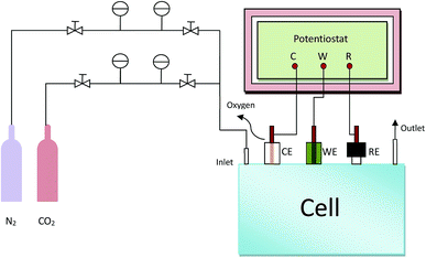
All the electrochemical measurements were carried out in a gastight H-cell, separated by a proton exchange membrane Nafion 117 between the anode and cathode cells. KHCO3 aqueous solution (0.5 M, 40 mL) as electrolyte was filled in each cell. A gas inlet and outlet is equipped on cathode cell, which is able to pass either purging gas or gaseous products through the solution. A conventional three-electrode system was used for the electrochemical performance tests. The prepared Sn@f-Ni electrode was used as working electrode, Pt mesh (20 × 20 mm2) and Ag/AgCl electrode (sat. KCl) served as counter electrode and reference electrode respectively. The scheme of the experimental electrolysis reaction unit is shown in Fig. 1. The cyclic voltammetry (CV) and chronocoulometry (CC) were conducted at ambient pressure and room temperature (25 °C) and the electrochemical data were recorded on a VersaSTAT3 electrochemical workstation (Princeton Applied Research, AMETEK. Co, USA). Before the experiment, the electrolyte was bubbled with N2 and CO2 for 30 min respectively. Thereafter, the pH values of N2-saturated and CO2-saturated 0.5 M KHCO3 electrolytes are determined as 7.5 and 7.3, respectively. CV curves were recorded in a potential window from 0.5 to −2.0 V vs. Ag/AgCl at a scan rate of 50 mV s−1. The current density (j) was normalized to the effective geometric surface area of the working electrode (2 cm2). If necessary for data processing, the potentials recorded against Ag/AgCl could convert to the reversible hydrogen electrode (RHE) potentials by the following equation: ERHE (V) = EAg/AgCl (V) + 0.197 V + 0.0591 × pHelectrolyte. Controlled potential electrolysis was performed with CC in the CO2-saturated electrolyte, and CO2 gas was continuously bubbled into the catholyte during the electrolysis with a flow rate of 13 mL min−1.2.4 Morphology and chemical structure investigation
The X-ray diffraction (XRD) patterns of the samples were measured on a D/MAX-2500 (Rigaku Co, Japan) with Cu Kα radiation with a scan rate of 5 degree min−1 ranging from 25 to 80°. Scanning electron microscopy (SEM) and energy dispersion spectroscopy (EDS) were recorded on a S-4800 (Hitachi Co. Japan) at an acceleration voltage of 3 kV.2.5 Product analysis
The gas phase products were detected by gas chromatography equipped with a thermal conductivity detector (TCD) (SP-6801, Shandong Lunan Ruihong Chemical Instrument Co., Ltd.) under high purity nitrogen carrier gas. The liquid phase products were acidized and quantified by a high performance liquid chromatography (LC 2010C, Shimadzu Corporation Co., Japan).The faradaic efficiency (FE) of H2, CO and formate are calculated by the equation: FE = 2nF/Q, where 2 means the number of electrons required for the formation of H2, CO or formate; n represents the generated moles of H2, CO and formate; Q is the amount of transferred charge through the electrolysis process.
3. Results and discussion
3.1 Characterization of Sn@f-Ni electrodes
The SEM images of Sn@f-Ni fabricated at different electrodeposition current are shown in Fig. 2. The low- and high-resolution SEM patterns demonstrate that the morphologies of the five samples have tremendous differences compared with the pure f-Ni surface (see in Fig. S1†) because of the rate of nucleation and growth process at different current. For the sample Sn@f-Ni-5, the flat coating layer of Sn suggests that many crystal nucleus formed on the fiber surface of f-Ni, but they have no chance to grow up because of the electrodeposition time limit. With current increases, the Sn coating layer is growing fast at the existing nucleation clusters, while the growth rate is slower where the nucleus is lacking. With the increase of current from 5.0 mA to 15.0 mA, more globular nodule-like grains appeared on the coating surface. It seems that the coating has more compact and uniform structure at the current of 15 mA, accompanied with the more globular grains (Fig. 2c and c′). Sn crystals with the size of about 2–3 μm are tightly bonded to Ni foam. When the deposition current was increased, the deposited Sn elements grew rapidly and irregularly on the surface of Ni foam. The particles were large and uneven of the surface as shown in Fig. 2d, d′, e and e′.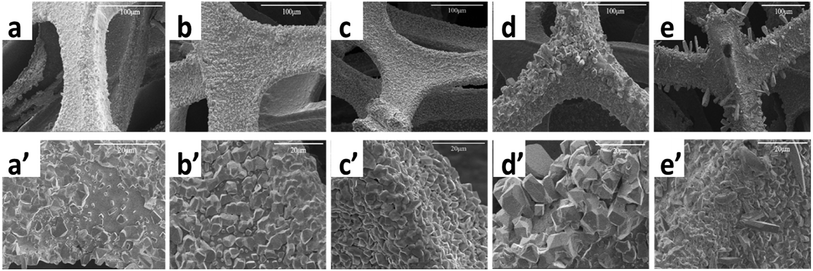 | ||
| Fig. 2 SEM images of Sn@f-Ni samples with different deposition currents ((a and a′) Sn@f-Ni-5; (b and b′) Sn@f-Ni-10; (c and c′) Sn@f-Ni-15; (d and d′) Sn@f-Ni-20; (e and e′) Sn@f-Ni-25). | ||
The result of weighing method demonstrated that the deposition amount is a function of current, while the weight increments has a slight decrease at higher current of 20 and 25 mA. The reason for this result may be that the fast crystallization at high current can reduce the number of exposed nucleus, and there is no extra surface for later particles to grow up.
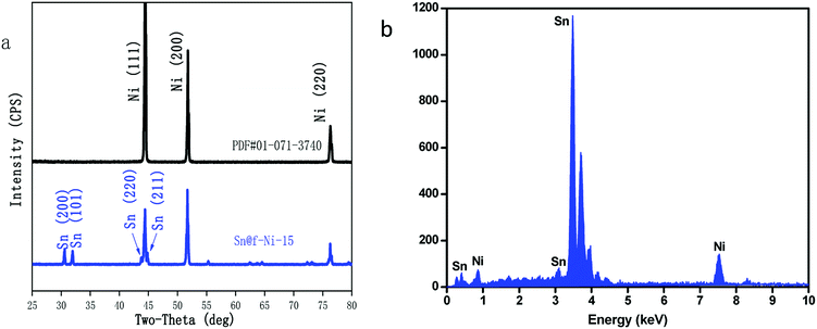
To exam the crystal structure and surface elements of Sn@f-Ni electrode, the Sn@f-Ni-15 sample was further analyzed by XRD and EDS. The XRD pattern of the as-prepared Sn@f-Ni electrode material is depicted in Fig. 3a.
The peaks located at 2θ = 44.5°, 51.8° and 76.3° are assigned to (111), (200) and (220) planes of Ni foam substrate (PDF #01-071-3740), the other diffraction peaks such as 2θ = 30.6°, 32°, 43.8° and 44.9° corresponds to (200), (101), (220) and (211) planes of Sn (PDF #01-086-2264), which is attributed to the presence of electrodeposited Sn metal. In addition, the evidences of impurity phase are not observed. At the same time, from the sharpness of the diffraction peak, the Sn metal electrodeposited on the Ni substrate has a high crystallinity.
Fig. 3b presents the element distribution of Sn@f-Ni-15 sample measured by EDS method. It can be seen from the figure that the peak of the Sn particles is larger than that of the Ni substrate. The result calculated from EDS data showed that 99.9% of the sample surface was covered with Sn element, and the high coverage surface is consistent with the results of XRD test.
3.2 Electrocatalyst performance test
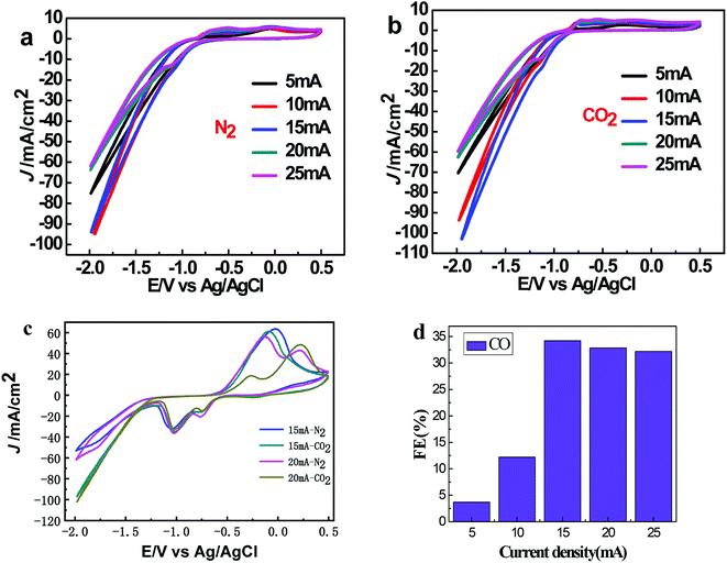
Fig. 4a and b exhibit the CV curves in N2 and CO2-saturated 0.5 M KHCO3 solution respectively for Sn@f-Ni electrodes fabricated at different deposition currents. It can be seen from both (a) and (b) that the current densities are very close at the deposition currents of 10 and 15 mA, which is more negative at a certain potential than that of the remaining three samples. As shown in Fig. 4c, the maximum difference of current density can be obtained for the Sn@f-Ni-15 electrode, implying the fabricated Sn@f-Ni electrode with the deposition current of 15 mA can exhibit highest performances in promoting the ER-CO2, and simultaneously inhibiting the HER. The faradaic efficiency toward CO of different samples is shown in Fig. 4d. Among these samples, Sn@f-Ni-15 sample has the highest faradaic efficiency. This is consistent with the results of the CV curve in Fig. 4c.To evaluate the kinetics of the carbon dioxide reduction, the Tafel plots derived from linear sweep voltammetry are presented in Fig. 5. When the current density is 5 mA, the Tafel slope is 77.6 mV dec−1, which is between 40 mV and 116 mV dec−1. The electrode (Sn@f-Ni-5) can be derived Volmer–Heyrovsky mechanism.16,17 The other four electrodes (Sn@f-Ni-10; Sn@f-Ni-15; Sn@f-Ni-20; Sn@f-Ni-25) have Tafel slopes have been over 100 mA dec−1. These slope are consistent with a rate-determining initial electron transfer to CO2 to form a surface adsorbed  intermediate, a mechanism that is commonly invoked for metal electrodes.18,19 During the electrolysis process, the possible reaction routes are as follows:
 | (1) |
| CO2 + H+(aq) + e− + ˙ → ˙COOH | (2) |
| ˙COOH + H+(aq) + e− → CO + H2O | (3) |
| H+(aq) + e− + ˙ → H˙ | (4) |
| H˙ + H+(aq) + e− → H2 | (5) |
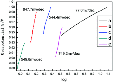 | ||
| Fig. 5 Tafel plots of different deposited current ((a) Sn@f-Ni-5; (b) Sn@f-Ni-10; (c) Sn@f-Ni-15; (d) Sn@f-Ni-20; (e) Sn@f-Ni-25). | ||
For 15 mA and 20 mA electrodes, the slopes are similar. A stable synthesis gas composition can be obtained by electrolysis at a potential of −1.7 V, which indicates that the Sn surface with high crystallinity conforms to the Heyrovsky–Volmer mechanism at a potential of −1.7 V.18
The exchange current density (i0) of the electrocatalyst, which describes the reaction rate at equilibrium potential and is another key parameter for evaluating electrode activity, is shown in Table S3.† The exchange current density of Sn@f-Ni-15 sample is 0.2064 mA cm−2, which is higher than the exchange current density of the other four electrodes. In summary, the results show that the Sn particles of the Sn@f-Ni-15 electrode have good dispersibility, maximum exchange current density, and maybe highest faradaic efficiency. The particle size and good dispersibility of the coated Sn crystals greatly improve the electrode activity.17 The result of electrolytic test (Table S1† and Fig. 5) can also demonstrate the electrode Sn@Ni-15 has better activity and selectivity.
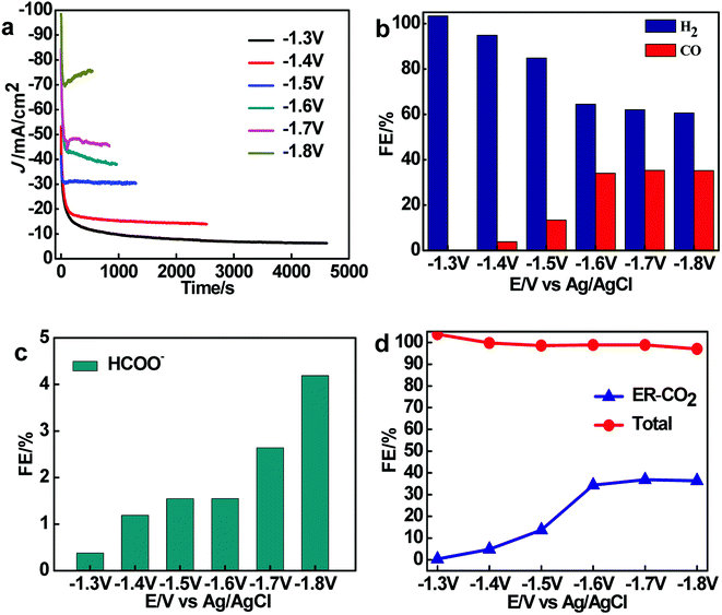
The ER-CO2 with Sn@Ni-15 sample as working electrode was performed at different electrolysis potentials range from −1.3 to −1.8 V, and the results are shown in Fig. 6. The i–t curves of ER-CO2 at different electrolysis potentials are shown in Fig. 6a. At the electrolysis potential of −1.8 V, the current density of ER-CO2 exhibits the highest value, but the corresponding stability is poor, while the high stability and low current densities of ER-CO2 are obtained at the other electrolysis potentials.
The FE for ER-CO2 to CO and producing H2 by using Sn@f-Ni at different electrolysis potentials were given in Fig. 6b. It can be seen that the FE for producing CO increases with the decreasing electrolytic potential from −1.3 to −1.8 V, explained by the inhibition of HER by ER-CO2 at low electrolytic potential.18–20 However, the FE of CO release decreases with continuously reduced cathode potential to −1.8 V, owing to the fact that HER becomes dominant, which is similar with those of reported Ag, Cu and Au as catalysts.21 The maximum FE toward CO is 34.23% and the FE of producing H2 is 62% by using Sn@f-Ni-15 electrode at the potential of −1.7 V. It can be calculated that the ratio of CO and H2 remains about 1![[thin space (1/6-em)]](https://www.rsc.org/images/entities/char_2009.gif) :
:![[thin space (1/6-em)]](https://www.rsc.org/images/entities/char_2009.gif) 2 in ER-CO2.
2 in ER-CO2.
It was found from Fig. 6c that the FE for ER-CO2 to HCOO− on the Sn@f-Ni is no more than 5% at different electrolysis potentials. While the FE of total reaction is around 100% (±4%) (Fig. 6d), and the FE of ER-CO2 reaction (reaction to form CO and HCOO−) at potential range from −1.8 to −1.6 V is close to 40%. The results indicate that the performance of the Sn@f-Ni-15 electrode is stable within the potential range. Meanwhile, the maximum FE of CO + H2 can reach 96.23% at the electrolysis potential of −1.7 V.
In order to investigate the stability of the Sn@f-Ni-15 electrode, the ER-CO2 reactions were carried out at −1.7 V. The i–t curves and the FE of CO and H2 at the electrolysis potential of −1.7 V are shown in Fig. 7. It can be observed that the current density as well as FE of CO and H2 can remain the certain values without obvious deviation. The results suggest that Sn@f-Ni-15 electrode can keep stable for a long operation time. In addition, the ratio of CO and H2 can maintain about 1![[thin space (1/6-em)]](https://www.rsc.org/images/entities/char_2009.gif) :
:![[thin space (1/6-em)]](https://www.rsc.org/images/entities/char_2009.gif) 2 in ER-CO2 for 3 h, which can be used as syngas. This is accordance with the reported noble metallic Au-coated nanowires electrode,22 except for low cost.
2 in ER-CO2 for 3 h, which can be used as syngas. This is accordance with the reported noble metallic Au-coated nanowires electrode,22 except for low cost.
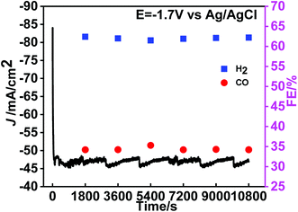 | ||
| Fig. 7 The i–t curves and FE of CO and H2 at the potential of −1.7 V vs. Ag/AgCl in CO2-saturated 0.5 M KHCO3 aqueous solution for 3 h. | ||
4. Conclusions
In summary, the Sn@f-Ni was prepared by the electrodeposition method and investigated by XRD, SEM and EDS measurements. Then Sn@f-Ni electrode was applied for the ER-CO2 to CO and H2 in an aqueous electrolyte. The electrochemical tests show that the Sn@f-Ni electrode deposited at current of 15 mA displays superior performances. Typically, the FE of CO and H2 can reach 34.23% and 62% respectively at the potential of −1.7 V vs. Ag/AgCl, and the electrode exhibits a large current density of 46 mA cm−2 and good stability in the process of electrolysis. More importantly, the ratio of CO and H2 generation is about 1![[thin space (1/6-em)]](https://www.rsc.org/images/entities/char_2009.gif) :
:![[thin space (1/6-em)]](https://www.rsc.org/images/entities/char_2009.gif) 2, which can be used as syngas for preparing more valuable fuels. Results revealed that the Sn@f-Ni electrode can be regarded as a potential alternative electrode for ER-CO2. The research work provides a simple method for the recycling economy of CO2 to relieve the dual pressure of present energy and environment.
2, which can be used as syngas for preparing more valuable fuels. Results revealed that the Sn@f-Ni electrode can be regarded as a potential alternative electrode for ER-CO2. The research work provides a simple method for the recycling economy of CO2 to relieve the dual pressure of present energy and environment.
Conflicts of interest
The authors declared that they have no conflicts of interest to this work. We declare that we do not have any commercial or associative interest that represents a conflict of interest in connection with the work submitted.Acknowledgements
The authors would like to express their appreciation for research funding provided by Key Basic Research Program of Hebei Province (No. 18964401D).References
- Z. Sun, T. Ma, H. Tao, Q. Fan and B. Han, Fundamentals and challenges of electrochemical CO2 reduction using two-dimensional materials, Chem, 2017, 3, 560–587 CAS.
- C. Cao and Z. Wen, Cu nanoparticles decorating rGO nanohybrids as electrocatalyst toward CO2 reduction, J. CO2 Util., 2017, 22, 231–237 CrossRef CAS.
- A. G. Saputro, R. I. Putra, A. L. Maulana, M. U. Karami, M. R. Pradana, M. K. Agusta, H. K. Dipojono and H. Kasai, Theoretical study of CO2 hydrogenation to methanol on isolated small Pdx clusters, J. Energy Chem., 2019, 35, 79–87 CrossRef.
- C. Kim, H. S. Jeon, T. Eom, M. S. Jee, H. Kim, C. M. Friend, B. K. Min and Y. J. Hwang, Achieving selective and efficient electrocatalytic activity for CO2 reduction using immobilized silver nanoparticles, J. Am. Chem. Soc., 2015, 137, 13844–13850 CrossRef CAS.
- (a) X. Zheng, P. DeLuna, F. deArquer, B. Zhang, N. Becknell, M. Ross, Y. Li, M. Banis, Y. Li and M. Liu, Joule, 2017, 1, 794–805 CrossRef CAS; (b) A. Klinkova, P. De Luna, C. T. Dinh, O. Voznyy, E. M. Larin, E. Kumacheva and E. H. Sargent, ACS Catal., 2016, 6, 8115–8120 CrossRef CAS.
- B. Zhang, L. Sun, Y. Wang, S. Chen and J. Zhang, Well-dispersed SnO2 nanocrystals on N-doped carbon nanowires as efficient electrocatalysts for carbon dioxide reduction, J. Energy Chem., 2020, 41, 7–14 CrossRef.
- Y. Ke, W. Guo-Xiong and B. Xin-He, Electrodeposited Sn-based Catalysts for CO2 Electroreduction, Chin. J. Struct. Chem., 2020, 39, 206–213 Search PubMed.
- S. Zhang, P. Kang and T. J. Meyer, Nanostructured tin catalysts for selective electrochemical reduction of carbon dioxide to formate, J. Am. Chem. Soc., 2014, 136, 1734–1737 CrossRef CAS.
- C. Reller, R. Krause, E. Volkova, B. Schmid, S. Neubauer, A. Rucki, M. Schuster and G. Schmid, Selective electroreduction of CO2 toward ethylene on nano dendritic copper catalysts at high current density, Adv. Energy Mater., 2017, 7, 1602114 CrossRef.
- K. Ye, A. Cao, J. Shao, G. Wang, R. Si, N. Ta, J. Xiao and G. Wang, Synergy effects on Sn-Cu alloy catalyst for efficient CO2 electroreduction to formate with high mass activity, Sci. Bull., 2020, 65, 711–719 CrossRef CAS.
- X. Jiang, X. Wang, Z. Liu, Q. Wang, X. Xiao, H. Pan, M. Li, J. Wang, Y. Shao and Z. Peng, A highly selective tin-copper bimetallic electrocatalyst for the electrochemical reduction of aqueous CO2 to formate, Appl. Catal., B, 2019, 259, 118040 CrossRef CAS.
- J. Zeng, K. Bejtka, W. Ju, M. Castellino, A. Chiodoni, A. Sacco, M. A. Farkhondehfal, S. Hernández, D. Rentsch and C. Battaglia, Advanced Cu-Sn foam for selectively converting CO2 to CO in aqueous solution, Appl. Catal., B, 2018, 236, 475–482 CrossRef CAS.
- (a) S. Sarfraz, A. Garcia-Esparza, A. Jedidi, L. Cavallo and K. Takanabe, ACS Catal., 6, 2842–2851 CrossRef CAS; (b) Y. Zhao, C. Wang and G. G. Wallace, J. Mater. Chem. A, 2016, 4, 10710–10718 RSC.
- Y. Zhao, C. Wang and G. G. Wallace, Tin nanoparticles decorated copper oxide nanowires for selective electrochemical reduction of aqueous CO2 to CO, J. Mater. Chem. A, 2016, 4, 10710–10718 RSC.
- Q. Li, J. Fu, W. Zhu, Z. Chen, B. Shen, L. Wu, Z. Xi, T. Wang, G. Lu and J.-j. Zhu, Tuning Sn-catalysis for electrochemical reduction of CO2 to CO via the core/shell Cu/SnO2 structure, J. Am. Chem. Soc., 2017, 139, 4290–4293 CrossRef CAS.
- M. Gattrell, N. Gupta and A. Co, A review of the aqueous electrochemical reduction of CO2 to hydrocarbons at copper, J. Electroanal. Chem., 2006, 594, 1–19 CrossRef CAS.
- S. Gao, X. Jiao, Z. Sun, W. Zhang, Y. Sun, C. Wang, Q. Hu, X. Zu, F. Yang and S. Yang, Ultrathin Co3O4 layers realizing optimized CO2 electroreduction to formate, Angew. Chem., Int. Ed., 2016, 55, 698–702 CrossRef CAS.
- B. Li, D. Li, W. Chen, Y. Liu, J. Zhang, Y. Wei, W. Zhang and W. Jia, Effect of current density and deposition time on microstructure and corrosion resistance of Ni-W/TiN nanocomposite coating, Ceram. Int., 2019, 45, 4870–4879 CrossRef CAS.
- M. A. Ashworth, G. D. Wilcox, R. L. Higginson, R. J. Heath, C. Liu and R. J. Mortimer, The effect of electroplating parameters and substrate material on tin whisker formation, Microelectron. Reliab., 2015, 55, 180–191 CrossRef CAS.
- L. Wu and A. J. Cobley, Investigation into the effects of magnetic agitation and pulsed current on the development of SnCu alloy electrodeposits, Thin Solid Films, 2019, 683, 118–127 CrossRef CAS.
- C. Delacourt, P. L. Ridgway and J. Newman, Mathematical modeling of CO2 reduction to CO in aqueous electrolytes I. kinetic study on planar silver and gold electrodes, J. Electrochem. Soc., 2010, 157, B1902–B1910 CrossRef CAS.
- K. Chen, X. Zhang, T. Williams, L. Bourgeois and D. R. MacFarlane, Electrochemical reduction of CO2 on core-shell Cu/Au nanostructure arrays for syngas production, Electrochim. Acta, 2017, 239, 84–89 CrossRef CAS.
Footnote |
| † Electronic supplementary information (ESI) available. See DOI: 10.1039/d0ra03477k |
| This journal is © The Royal Society of Chemistry 2020 |

