 Open Access Article
PVDF-supported graphene foam as a robust current collector for lithium metal anodes†
Liurong Shi *ab,
Zhipeng Hub and
Ye Hongb
aSchool of Physics, Peking University, Beijing, 100871, P. R. China. E-mail: shiliurong@gacrnd.com
bGAC Automotive Research & Development Center, Ltd, Guangzhou, 511434, P. R. China
First published on 2nd June 2020
Abstract
Lithium metal batteries have drawn much attention due to their ultrahigh energy density. However, the safety hazards and limited lifetime caused by severe lithium dendrite growth during cycling hinder their real application. To address this issue and improve the electrochemical performance of current lithium batteries, a current collector beyond the traditional copper foil for lithium anodes is highly needed. We proposed and prepared a PVDF-supported graphene foam (PSGF) structure as an effective current collector for lithium metal anodes. Because of its structural stability, large surface area, and lithiophilic surface chemistry, the corresponding lithium metal anode (PSGF@Li) shows an extended cycling life (∼1000 h), a decreased voltage hysteresis (∼80 mV) and an improved coulombic efficiency (∼99%). Furthermore, the practical application of the PSGF@Li anode in a full cell system was also demonstrated.
Introduction
With the fast development of electric vehicles (EVs), the demand for long driving mileage keeps growing. The limited energy density of current lithium ion batteries was considered as the bottleneck of extending the driving mileage of EVs.1 In this content, lithium metal batteries were reconsidered because of their potential high energy density derived from the ultrahigh theoretical capacity (3860 mA h g−1) and ultralow electrochemical potential (−3.040 V versus standard hydrogen electrode) of lithium metal anodes.2–4 However, the severe dendrite growth of lithium anodes during cell cycling inevitably causes fast capacity decay and potential safety hazards from the battery, thus hindering its real application.5,6The current collectors play important roles in batteries and copper foil has been used as a commercial anodic current collector for a long time due to its high conductivity, large-scale production and good electrochemical stability.7 But it shows limitations when it comes to the lithium anode.8 The limited surface area of two dimensional copper foil is not able to well disperse the current density applied, which will result in the growth of dendritic lithium. What's more, after repeated lithium plating and stripping processes, the lithium metal is easy to be peeled off from the current collector and becomes “dead” lithium losing efficient electrical contacts. Given this, novel effective current collectors for lithium metal anode should be developed.9–11
Recently, several three dimensional carbon materials have been used as current collectors for lithium metal anodes. They have been proved to be highly effective in tailoring the nucleation and deposition behavior of lithium metal and thus improving the electrochemical performance of lithium metal anode.12,13 However, the carbonous current collectors are electrochemical active and inevitably undergo repeated lithiation and delithiation reactions during the charge and discharge processes. In this case, structural damages are introduced into the electrodes and cause battery performance decay. Herein, we designed a polyvinylidene fluoride supported graphene foam (PSGF) structure as a robust and effective current collector for lithium metal anode. The supporting PVDF layer was coated on CVD-grown graphene foam via vacuum-filtration. By applying the prepared PSGF as current collector for lithium metal anode, the lithium dendrite growth was suppressed to a certain degree. As a result, the short circuit time of PSGF combined Li (denoted as PSGF@Li) anode was extended to 1000 hours and the voltage hysteresis of lithium stripping and plating was decreased and stabilized. Besides, the PSGF@Li anode tends to form stable SEI film and exhibits a high coulombic efficiency up to ∼99%. Specifically, the graphene foam structure keeps stable during the repeated battery cycling owing to the support of PVDF coating layer. Furthermore, the full battery based on LiNi0.8Co0.15Al0.05O2 (denoted as NCA) cathode and PSGF@Li anode also exhibits a better cycling stability than that of Cu@Li/NCA full cell.
Results and discussion
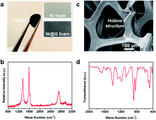
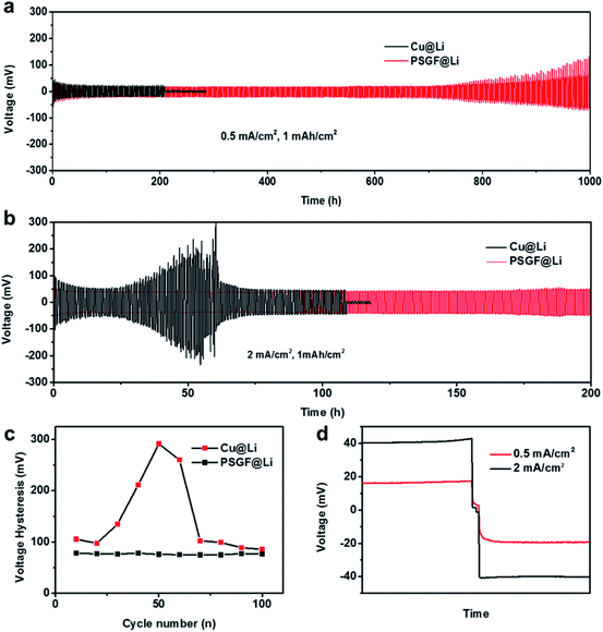
The preparation procedure of the PSGF using nickel foam is described as below. First, a piece of nickel foam was used as the substrate to grow graphene via a traditional CVD method.14,15 After a typical CVD process, the obtained graphene covered nickel foam (Ni@G) was coated by 5% solution of PVDF in NMP. Experimentally, vacuum-filtration technology was chosen as the coating method. The thickness of the PVDF coating layer over graphene foam was less than 100 nm (Fig. S1†). The PVDF coated Ni@G foam was then immersed in diluted hydrochloric acid to remove the core nickel metal. After the cleaning and drying process, the target PSGF sample was obtained. Fig. 1a shows the photograph of a freestanding flexible PSGF cut into circle shape and the insets are the photographs of the pristine nickel foam and the CVD grown Ni@G foam, respectively. The thickness of the obtained PSGF sample was about 1 mm. Because of the large-scale production ability of nickel foam and the feasibility of CVD process, the preparation of PSGF is easy to scale up. Raman spectrum conducted on Ni@G foam (Fig. 1b) demonstrates the quality of the grown graphene. The relatively high intensity of G band (located at 1586 cm−1) indicates a highly graphitized nature of the CVD grown graphene. Also, the observation of D band (located at 1357 cm−1) indicates the existence of structural defects in the grown graphene.16,17 The defects in the graphene structure are beneficial for the infiltration of electrolyte and diffusion of lithium ions when used in battery. The SEM image in Fig. 1c clearly shows the three dimensional morphology of the PSGF, which is inherited from the morphology of Ni foam. From the marked area, the hollow structure is clearly observed and indicates the bicontinuous feature of the PSGF. The hollow space can provide an extra room for the accommodation of lithium metal, thus avoid the mechanical exfoliation and electrical isolation of lithium metal. The effective coating of PVDF was demonstrated by the FTIR spectrum (Fig. 1d). The IR transmittance peaks located at ∼880 and ∼837 cm−1 indicate the presence of the β phase of PVDF on the surface of PSGF.18 With the support of PVDF, the PSGF is robust enough to be applied as current collector for lithium metal anode.Lithium metal was first electro-deposited on the prepared PSGF and copper foil to obtain corresponding lithium metal anodes, which are denoted as PSGF@Li and Cu@Li, respectively. To evaluate their galvanostatic cycling performances, symmetrical cells were fabricated and tested. Fig. 2a shows the comparison of voltage profiles of the two types of symmetrical cells cycling at 0.5 mA cm−2 with a fixed capacity of 1 mA h cm−2. For Cu@Li symmetrical cell, a short-circuit happened at a cycling time of 208 h.19 In contrast, the PSGF@Li symmetrical cell exhibits a stable cycling up to 1000 hours without short circuit. The same trend was observed when the current density was increased to 2 mA cm−2 (Fig. 2b). The Cu@Li symmetrical cell shows a shortened short-circuit time of 108 hours while the PSGF@Li symmetrical cell can stably cycle for more than 200 hours. As is known, the internal short-circuit is usually originated from the penetration of the separator by the lithium dendrite. According to the Sand's time model, the lithium dendrite growth will be suppressed when the current density is decreased.20–22 Benefit from the large surface area provided by the three dimensional PSGF current collector, the current density applied is well dispersed and decreased. As a consequence, the growth of lithium dendrite was suppressed and the short circuit was forbidden in the PSGF@Li anodes.23,24 What's more, the unique hollow structure in PSGF provides an extra and confined room for Li accommodation, which is helpful for the forbidden of cell failure. Therefore, a long lifespan of the PSGF@Li anode is expected and observed.
Besides the extending of cycling life, the voltage hysteresis was decreased and stabilized in PSGF@Li symmetrical cell. The voltage hysteresis is defined as the difference between the voltage of lithium plating and stripping, which is influenced by the interfacial properties and current density.25,26 According to the statistical results in Fig. 2c, the symmetrical cell of the PSGF@Li exhibits a voltage hysteresis of ∼80 mV, which is smaller than that of Cu@Li. The small voltage hysteresis indicates a lowered lithium deposition barrier on PSGF. As demonstrated previously, the O atoms in defective graphene are expected to create a lithiophilic surface on PSGF, thus reducing the overpotential of lithium plating (Fig. S2 and Table S1†).27 The voltage hysteresis of PSGF@Li symmetrical cell also shows a smaller fluctuation than that of Cu@Li symmetrical cell, indicating a stable interface on PSGF@Li. In short, not only the three dimensional morphology but also the surface chemistry of PSGF contributes to the modified lithium deposition behavior (Fig. S3†). Current density also influences the lithium deposition behaviors in the cells. As shown in Fig. 2d, the overpotential of lithium plating and stripping of PSGF@Li anode is increased at high current density (2 mA cm−2) because of the enhanced polarization with the increase of current density.
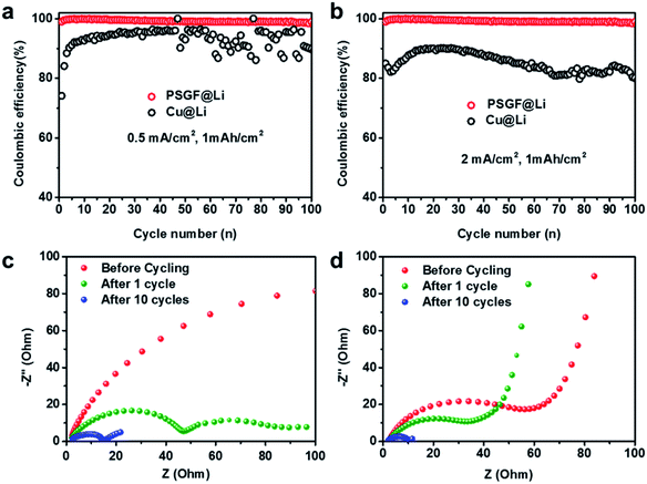
Coulombic efficiency is widely used to evaluate the reversibility of repeated Li plating and stripping processes and have been an important indicator for predicting the cycling life of lithium metal batteries. Asymmetric cells were fabricated to measure the coulombic efficiencies of Cu@Li and PSGF@Li anodes. The breakdown and reconstruction of the SEI film was the main reason for the loss of active lithium and the low coulombic efficiency.28 Resulted from the high reversibility of Li plating and striping on PSGF, a uniform and stable SEI film was formed on the surface of PSGF@Li anode. Consequently, the PSGF@Li anode exhibits fairly stable and high coulombic efficiency up to ∼99% for 100 cycles at a current density of 0.5 mA cm−2 with an areal capacity of 1 mA h cm−2 (Fig. 3a). By contrast, the Cu@Li anode shows a rather low and unstable coulombic efficiency especially in the later 50 cycles. At high current density of 2 mA cm−2 (Fig. 3b), the coulombic efficiency of Cu@Li undergoes an obvious drop compared with that of 0.5 mA cm−2. It's noted that the PSGF@Li still exhibits a stable and high coulombic efficiency up to ∼99%, which indicates a prolonged cycling life. However, it still takes a long way to reach the ultrahigh coulombic efficiency of 99.99% required for the long-life battery, other factors such as the electrolyte and the electrode structure should be considered and such works are going on in our lab.3,28,29 To further clarify the interfacial properties of the two different current collectors, EIS, a powerful tool to provide information on the SEI film was employed. The semicircle at the high frequency range in the Nyquist plots indicates the interfacial resistance at SEI and the charge-transfer resistance at the Li metal anode surface. The impedances of the PSGF@Li sample are 74, 34 and 5 Ω for before cycling, after 1 cycle and after 10 cycles, which is much lower than that of the copper foil (>200, 49, 15 Ω for before cycling, after 1 cycle and after 10 cycles, respectively), further supporting the significantly improved stability of the built SEI on PSGF@Li (Fig. 3c and d). In this regard, the cycling life of lithium metal battery comprised of PSGF@Li anode should be extended due to the constructed stable SEI film and high coulombic efficiency.
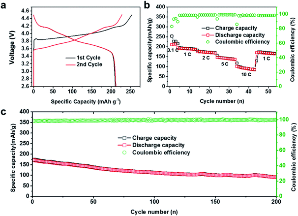
As mentioned above, the PSGF current collector can effectively devote to the uniform lithium deposition, stable SEI construction, and prolonged cycling stability. The advantageous electrochemical performance of the PSGF current collector enables its practical application in a full battery system. For full cell setup, PSGF@Li and Cu@Li anodes were firstly paired with NCA cathodes with areal mass loading of 7 mg cm−2 in carbonate based electrolyte. Fig. 4a shows the charge–discharge profiles of the assembled full cell at 0.1C in the first two cycles. Remarkably, the full cell exhibited a high specific capacity of 220 mA h g−1 (based on NCA mass). Fig. 4b shows the rate performance of PSGF@Li/NCA full cell. At a low rate of 0.1C, the full cell was able to offer a cycling specific capacity of 220 mA h g−1. The fluctuation of the capacitance and the coulombic efficiency in the early cycles was due to the construction of SEI film on the surface of lithium metal anode. Under high rates, PSGF@Li/NCA cell was capable to provide a specific capacity of ∼193 mA h g−1 under 1C, ∼176 mA h g−1 under 2C, ∼148 mA h g−1 under 5C, ∼100 mA h g−1 under 10C, and finally return to ∼170 mA h g−1 under 1C. Notably, PSGF@Li/NCA full cell showed a higher cycling stability than that of Cu@Li/NCA cell. At a high current density of 1C, the capacity retention of the PSGF@Li/NCA full cell after 200 cycles is up to ∼60% (Fig. 4c). However, the capacity of the Cu@Li/NCA full cell displayed a sudden drop after 100 cycles (Fig. S4†). The failure of Cu@Li/NCA full cell was mainly caused by the exhaustion of active lithium ions because of the rather low coulombic efficiency of Cu@Li anode. What's more, the structural stability of the PSGF current collector also contributes to the cycling stability of the PSGF@Li/NCA full cell. According to the post-mortem observation of the anode after 200 cycles, the PSGF exhibits a stable structure (Fig. S5†). The results above further confirmed the capability of PSGF@Li as a high performance anode with improved rate capability and cycling stability in a full cell for commercial applications.
Conclusions
In summary, we have prepared the PSGF using a modified CVD process for preparing graphene foam. The prepared PSGF was used as an effective current collector for lithium metal anode. The graphene foam in PSGF provides a large surface area for well dispersing the current density applied, thus the growth of lithium dendrite was suppressed. Besides, the numerous O atoms in the defective graphene foam can work as lithiophilic sites to decrease the lithium nucleation barrier, thus enabling a highly reversible and uniform lithium deposition. What's more, the PVDF layer on the surface of graphene foam helps supporting the three dimensional graphene structure and preventing the structure from collapsing during repeated lithiation and delithiation processes. In short, the prepared PSGF with the robust three dimensional structure and the lithiophilic surface chemistry fulfills the rigorous demands of current collector for lithium metal anode. The corresponding batteries show improved electrochemical performances including long cycling life, low voltage hysteresis and high coulombic efficiency. Due to the facility of preparation and the advantage in battery performance, the research of PSGF current collector should push the real application of lithium metal batteries forward.Experimental section
Material synthesis and characterization
Nickel foam (purchased from Kejing Star Technology Co., LTD.) was placed inside a CVD furnace for graphene growth. First, the furnace was heated to 950 °C with the protection of Ar (300 sccm) at ambient pressure. Then, ethanol was introduced into the furnace as carbon source by a constant gas flow of Ar (50 sccm) for 5 min. Ni@G foam was obtained after the furnace was cooled down to room temperature. To coat PVDF layer over graphene, 1 mL 5% solution of PVDF in NMP was filtrated through the Ni@G foam in 20 seconds. After removing the nickel core, the PSGF sample was obtained. The prepared samples were characterized using SEM (Hitachi S-4800; acceleration voltage 5–30 kV), Raman spectroscopy (Jobin Yvon LabRAM HR 800UV; 514.5 nm, 25 mW), XPS (Kratos, Axis Ultra, Mg Kα as the excitation source), FTIR (Bruker, VERTEX 70).Battery fabrication and analysis
2032-type stainless steel coin cells were used to assemble the testing half and full cells. The coin-type cells were assembled in an Ar-filled glove box (MBraun Unilab). Clegard 2325 membrane and 1 M LiPF6 in ethylene carbonate (EC) and diethyl carbonate (DEC) (1![[thin space (1/6-em)]](https://www.rsc.org/images/entities/char_2009.gif) :
:![[thin space (1/6-em)]](https://www.rsc.org/images/entities/char_2009.gif) 1; v/v) were used as separator and electrolyte, respectively. The areas of the electrodes in symmetric cells, asymmetric cells, and full cells are both 1.54 cm2. For the symmetric cells, 5 mA h cm−2 Li was first pre-deposited on the PSGF and copper foil under a current density of 0.5 mA cm−2 in half cells. Then the PSGF@Li and Cu@Li electrodes were extracted from the half cells and corresponding symmetrical cells were assembled. For the asymmetric cells, Li foils were paired with PSGF and copper foil directly and the same cells were used for further coulombic efficiency measurements. For the preparation of the NCA cathodes in the full cells, slurries were prepared by mixing NCA
1; v/v) were used as separator and electrolyte, respectively. The areas of the electrodes in symmetric cells, asymmetric cells, and full cells are both 1.54 cm2. For the symmetric cells, 5 mA h cm−2 Li was first pre-deposited on the PSGF and copper foil under a current density of 0.5 mA cm−2 in half cells. Then the PSGF@Li and Cu@Li electrodes were extracted from the half cells and corresponding symmetrical cells were assembled. For the asymmetric cells, Li foils were paired with PSGF and copper foil directly and the same cells were used for further coulombic efficiency measurements. For the preparation of the NCA cathodes in the full cells, slurries were prepared by mixing NCA![[thin space (1/6-em)]](https://www.rsc.org/images/entities/char_2009.gif) :
:![[thin space (1/6-em)]](https://www.rsc.org/images/entities/char_2009.gif) Super P
Super P![[thin space (1/6-em)]](https://www.rsc.org/images/entities/char_2009.gif) :
:![[thin space (1/6-em)]](https://www.rsc.org/images/entities/char_2009.gif) PVDF (8
PVDF (8![[thin space (1/6-em)]](https://www.rsc.org/images/entities/char_2009.gif) :
:![[thin space (1/6-em)]](https://www.rsc.org/images/entities/char_2009.gif) 1
1![[thin space (1/6-em)]](https://www.rsc.org/images/entities/char_2009.gif) :
:![[thin space (1/6-em)]](https://www.rsc.org/images/entities/char_2009.gif) 1) in NMP and cast on aluminum foils by a doctor blade method. After vacuum drying at 120 °C for 12 h, the NCA cathode was obtained. The discharge and charge measurements of the batteries were performed on a Land (CT2001A) system at room temperature. The electrochemical impedance spectroscopy was carried out on electrochemical workstation (Bio-Logic).
1) in NMP and cast on aluminum foils by a doctor blade method. After vacuum drying at 120 °C for 12 h, the NCA cathode was obtained. The discharge and charge measurements of the batteries were performed on a Land (CT2001A) system at room temperature. The electrochemical impedance spectroscopy was carried out on electrochemical workstation (Bio-Logic).
Conflicts of interest
There are no conflicts to declare.Acknowledgements
This work was financially supported by Chinese Postdoctoral Science Foundation (2019M650192).References
- J. W. Choi and D. Aurbach, Nat. Rev. Mater., 2016, 1, 16013 CrossRef CAS.
- B. Scrosati and J. Garche, J. Power Sources, 2010, 195, 2419–2430 CrossRef CAS.
- X.-B. Cheng, R. Zhang, C.-Z. Zhao and Q. Zhang, Chem. Rev., 2017, 117, 10403–10473 CrossRef CAS PubMed.
- H. Wang, D. Yu, C. Kuang, L. Cheng, W. Li, X. Feng, Z. Zhang, X. Zhang and Y. Zhang, Chem, 2019, 5, 313–338 CAS.
- D. Lin, Y. Liu and Y. Cui, Nat. Nanotechnol., 2017, 12, 194–206 CrossRef CAS PubMed.
- B. Liu, J.-G. Zhang and W. Xu, Joule, 2018, 2, 833–845 CrossRef CAS.
- J. B. Goodenough and K. S. Park, J. Am. Chem. Soc., 2013, 135, 1167–1176 CrossRef CAS PubMed.
- M. Chen, L. Cheng, J. Chen, Y. Zhou, J. Liang, S. Dong, M. Chen, X. Wang and H. Wang, ACS Appl. Mater. Interfaces, 2020, 12, 3681–3687 CrossRef CAS PubMed.
- Q. Li, S. Zhu and Y. Lu, Adv. Funct. Mater., 2017, 27, 1606422 CrossRef.
- C.-P. Yang, Y.-X. Yin, S.-F. Zhang, N.-W. Li and Y.-G. Guo, Nat. Commun., 2015, 6, 8058 CrossRef CAS PubMed.
- Y. An, H. Fei, G. Zeng, X. Xu, L. Ci, B. Xi, S. Xiong, J. Feng and Y. Qian, Nano Energy, 2018, 47, 503–511 CrossRef CAS.
- Z. Li, X. Li, L. Zhou, Z. Xiao, S. Zhou, X. Zhang, L. Li and L. Zhi, Nano Energy, 2018, 49, 179–185 CrossRef CAS.
- J. Zhao, G. Zhou, K. Yan, J. Xie, Y. Li, L. Liao, Y. Jin, K. Liu, P.-C. Hsu, J. Wang, H.-M. Cheng and Y. Cui, Nat. Nanotechnol., 2017, 12, 993–999 CrossRef CAS PubMed.
- Z. Chen, W. Ren, L. Gao, B. Liu, S. Pei and H.-M. Cheng, Nat. Mater., 2011, 10, 424–428 CrossRef CAS PubMed.
- K. Chen, L. Shi, Y. Zhang and Z. Liu, Chem. Soc. Rev., 2018, 47, 3018–3036 RSC.
- L. Shi, C. Pang, S. Chen, M. Wang, K. Wang, Z. Tan, P. Gao, J. Ren, Y. Huang, H. Peng and Z. Liu, Nano Lett., 2017, 17, 3681–3687 CrossRef CAS PubMed.
- L. Lin, B. Deng, J. Sun, H. Peng and Z. Liu, Chem. Rev., 2018, 118, 9281–9343 CrossRef CAS PubMed.
- G. P. Zheng, Z. Y. Jiang, Z. Han and J. H. Yang, eXPRESS Polym. Lett., 2016, 10, 1 CrossRef.
- C.-P. Yang, Y.-X. Yin, S.-F. Zhang, N.-W. Li and Y.-G. Guo, Nat. Commun., 2015, 6, 8058 CrossRef CAS PubMed.
- A. Jana, S. I. Woo, K. S. N. Vikrant and R. E. García, Energy Environ. Sci., 2019, 12, 3595–3607 RSC.
- X. He, S. Schmohl and H. D. Wiemhöfer, ChemElectroChem, 2019, 6, 1166–1176 CrossRef CAS.
- L. A. Selis and J. M. Seminario, RSC Adv., 2019, 9, 27835–27848 RSC.
- S. Huang, H. Yang, J. Hu, Y. Liu, K. Wang, H. Peng, H. Zhang and L. Z. Fan, Small, 2019, 15, e1904216 CrossRef PubMed.
- K. Xie, W. Wei, K. Yuan, W. Lu, M. Guo, Z. Li, Q. Song, X. Liu, J. G. Wang and C. Shen, ACS Appl. Mater. Interfaces, 2016, 8, 26091–26097 CrossRef CAS PubMed.
- C. Jin, O. Sheng, J. Luo, H. Yuan, C. Fang, W. Zhang, H. Huang, Y. Gan, Y. Xia, C. Liang, J. Zhang and X. Tao, Nano Energy, 2017, 37, 177–186 CrossRef CAS.
- L. Liu, Y.-X. Yin, J.-Y. Li, S.-H. Wang, Y.-G. Guo and L.-J. Wan, Adv. Mater., 2018, 30, 1706216 CrossRef PubMed.
- Y. Liu, X. Qin, S. Zhang, L. Zhang, F. Kang, G. Chen, X. Duan and B. Li, J. Mater. Chem. A, 2019, 7, 13225–13233 RSC.
- S. Jurng, Z. L. Brown, J. Kim and B. L. Lucht, Energy Environ. Sci., 2018, 11, 2600–2608 RSC.
- H. Wang, D. Yu, X. Wang, Z. Niu, M. Chen, L. Cheng, W. Zhou and L. Guo, Angew. Chem., Int. Ed., 2019, 58, 16451–16455 CrossRef CAS PubMed.
Footnote |
| † Electronic supplementary information (ESI) available. See DOI: 10.1039/d0ra03352a |
| This journal is © The Royal Society of Chemistry 2020 |


