 Open Access Article
Synthesis and characterization of a novel crosslinkable side-chain sulfonated poly(arylene ether sulfone) copolymer proton exchange membranes†
Shouping Wang,
Fugang He,
Qiang Weng,
Diao Yuan,
Pei Chen*,
Xinbing Chen * and
Zhongwei An
Key Laboratory of Applied Surface and Colloid Chemistry (MOE), Shaanxi Key Laboratory for Advanced Energy Devices, Shaanxi Engineering Laboratory for Advanced Energy Technology, School of Materials Science and Engineering, Shaanxi Normal University, Xi'an 710119, PR China. E-mail: chenxinbing@snnu.edu.cn; chenpei@snnu.edu.cn
First published on 30th June 2020
Abstract
A series of novel crosslinkable side-chain sulfonated poly(arylene ether sulfone) copolymers (S-SPAES(x/y)) was prepared from 4,4′-biphenol, 4,4′-difluorodiphenyl sulfone, and a new difluoro aromatic monomer 1-(2,6-difluorophenyl)-2-(3,5-dimethoxyphenyl)-1,2-ethanedione (DFDMED) via co-polycondensation, demethylation, and further nucleophilic substitution of 1,4-butane sultone. Meanwhile, quinoxaline-based crosslinked copolymers (CS-SPAES(x/y)) were obtained via cyclo-condensation between S-SPAES(x/y) and 3,3′-diaminobenzidine. Both the crosslinkable and crosslinked copolymer membranes exhibit good mechanical properties and high anisotropic membrane swelling. Crosslinkable S-SPAES(1/2) with an ion exchange capacity (IEC) of 2.01 mequiv. g−1 displays a relatively high proton conductivity of 180 mS cm−1 and acceptable single-cell performance, which is attributed to its good microphase separation resulting from the side-chain sulfonated copolymer structures. Compared with S-SPAES(1/1) (IEC of 1.68 mequiv. g−1), crosslinked CS-SPAES(1/2) with a comparable IEC exhibits a larger conductivity of 157 mS cm−1, and significantly higher oxidative stability and lower membrane swelling, suggesting a distinct performance improvement due to the quinoxaline-based crosslinking.
1. Introduction
Polymer electrolyte membrane (PEM) fuel cells have been widely studied for years and focused on the achievement of promising clean energy sources for transportation, and stationary and portable power applications due to their low polluting capability and good power density,1–3 wherein PEM, as one of the key components for achieving ion conduction and obstructing fuel crossover, has attracted widespread interest. Among the reported PEMs, perfluorosulfonate ionomers exhibit large proton conductivity and good stability4–6 but the high cost and large fuel crossover encumber their further applications in fuel cells.7 Up to now, many kinds of sulfonated aromatic ionomers with good performance have been extensively developed to act as PEMs.8–25 In general, the ionomers are prepared via a post-sulfonation strategy, in which sulfonic acid groups are directly introduced into the polymer structures bearing the reactive sites,10–13,15,17,21,25 as well as through a pre-sulfonation method achieved from copolymerization between sulfonated and non-sulfonated monomers.8,22,26–28Among the reported sulfonated aromatic copolymers for fuel cell applications, poly(arylene ether) based ionomers are the most studied,10–12,14,15,22–25,27,28 which is attributed to their good stability and easy fabrication. However, the sulfonated poly(arylene ether sulfone) (PAES) with high ion exchange capacity (>2.0 mequiv. g−1) generally exhibits large swelling, which leads to undesirable qualities in the fuel cells. Therefore, many efforts have been focused on developing novel sulfonated PAES structures with acceptable membrane swelling and good proton conductivity, in which the crosslinking method and side-chain strategies are commonly utilized to suppress swelling and improve the conductivity.11,18,22,27,28
In recent years, several kinds of crosslinking methods have been reported to develop novel crosslinked PEMs with high performance, including ionically-crosslinked acid/base blend membranes,29 covalently-crosslinked membranes via esterification reaction,30 thermally-activated covalent crosslinked membranes,31–33 covalently-crosslinked membranes via thermally or photochemically-activated radical crosslinking reaction,34–36 and quinoxaline-based covalent ionically-crosslinked membranes.27,28,37,38 Crosslinking is considered to be effective to balance the membrane properties but there are few reported crosslinkable monomers or copolymers for PEMs. Crosslinkable groups in the monomer contribute to the formation of a covalently-crosslinked structure and to achieve reduced sulfonic acid consumption for ionic or covalent crosslinking, such as propenyl groups for thermally- or photochemically-activated radical crosslinking34 and benzil groups for quinoxaline-based crosslinking.27 Here, a new difluoro aromatic monomer 1-(2,6-difluorophenyl)-2-(3,5-dimethoxyphenyl)-1,2-ethanedione (DFDMED) with crosslinkable ethanedione and ionizable dimethoxy groups was designed and synthesized; meanwhile, DFDMED-based crosslinkable side-chain poly(arylene ether sulfone) copolymers bearing pendant butanesulfonic acid were prepared from 4,4′-biphenol, 4,4′-difluorodiphenyl sulfone, and DFDMED. Furthermore, quinoxaline-based crosslinked copolymers were obtained via cyclo-condensation between the crosslinkable copolymers and 3,3′-diaminobenzidine. The properties of the crosslinkable and crosslinked copolymer membranes, such as proton conductivity, membrane swelling, water uptake, methanol permeability, oxidative stability, and fuel cell performance, have been investigated and discussed.
2. Experimental
2.1. Materials and reagents
4,4′-Difluorodiphenyl sulfone (DFDPS) and 3,5-dimethoxybenzyl bromide was obtained from Beijing Zhongsheng Huateng Technology Co. Ltd. and Zhejiang Shouerfu Chemical Co. Ltd, respectively. 4,4′-Biphenol (BP) and 3,3′-diaminobenzidine (DAB) were acquired from Shanghai Aladdin Reagent Co. Ltd. Other solvents and reagents were purchased from Sinopharm Chemical Reagent.2.2. Preparation of the difluoro aromatic monomer DFDMED
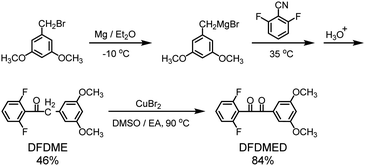
Two-step reactions including the nucleophilic addition of 2,6-difluorobenzonitrile and oxidation of the corresponding 1,2-disubstituted ethanone were utilized to prepare the difluoro aromatic monomer DFDMED, which contains a crosslinkable ethanedione and two ionizable dimethoxy groups, as shown in Scheme 1. The synthetic procedure is described below.Characterization data of DFDME: 1H-NMR (300 MHz, D3CCOCD3, TMS): δ (ppm) 3.74 (s, 6H), 4.13 (s, 2H), 6.34 (s, 1H), 6.37 (s, 2H), 6.90 (t, 2H), 7.35 (m, 1H). IR (KBr, pellet, cm−1): 3060, 3030, 2947, 2860, 1625, 1586, 1565, 1466, 1234, 1137, 1050, 810, 773. EI-MS m/z (rel. int.): 292.17 (M+, 30), 264.17 (37), 151.16 (18), 141.03 (100), 113.08 (10), 91.06 (6).
Characterization data of DFDMED: 1H-NMR (300 MHz, DMSO-d6, TMS): δ (ppm) 3.83 (s, 6H), 6.94 (s, 1H), 7.12 (s, 2H), 7.34 (t, 2H), 7.78–7.88 (m, 1H). IR (KBr, pellet, cm−1): 3097, 2918, 2859, 1695, 1647, 1596, 1546, 1514, 1460, 1368, 1235, 1135, 1045, 855, 808, 671. EI-MS m/z (rel. int.): 306.22 (M+, 6), 165.13 (100), 137.12 (23), 122.08 (17), 107.11 (10).
2.3. Preparation of DFDMED-based side-chain sulfonated copolymers (S-SPAES(x/y))
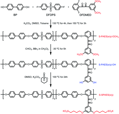
A series of side-chain sulfonated copolymers BP-DFDPS/DFDMED(x/y) (coded as S-SPAES(x/y)), where x/y refers to the molar ratio of DFDPS to DFDMED, was obtained via one-pot high temperature copolymerization, as well as demethylation and further nucleophilic substitution, as shown in Scheme 2. Herein, the synthetic procedure of S-SPAES(1/1) is chosen as an example and described below.2.4. Fabrication of proton exchange membranes
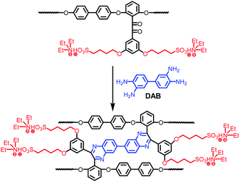
The crosslinkable copolymer membrane was fabricated via a casting method, whose procedure is described as follows. The obtained copolymer was firstly dissolved in DMSO to obtain a 5 wt% solution and then the solution was filtered. The resulting filtrate was cast onto a glass plate at 80 °C, which was dried at 100 °C for 12 h. The as-cast salt form membrane was immersed in 1 M HCl solution at 50 °C for 48 h to achieve proton exchange. Then, the membrane was soaked in water at 40 °C for hours and thoroughly washed with deionized water until the rinsed water became neutral. After drying in vacuum at 100 °C for 12 h, the proton exchange membrane with a thickness of 40–70 μm was obtained.The crosslinked copolymers BP-DFDPS/DFDMED/DAB(x/y/z) (coded as CS-SPAES(x/y)) were prepared via the cyclo-condensation of DAB and the benzil group in the DFDMED unit, where the quinoxaline cross-linkages were built in the copolymer structures, as shown in Scheme 3. In the synthetic procedures, the molar content of DAB was set to 30 mol% based on DFDMED for all the crosslinked membranes; in other words, z = 0.3y. The crosslinked copolymer membranes could be prepared via the following procedure. The copolymer S-SPAES(x/y) in salt form was changed to the proton form via soaking in 1 M HCl solution at 50 °C for 48 h. The obtained proton form S-SPAES(x/y) was filtered and washed three times with deionized water, and then immersed in trimethylamine for 72 h to give the ammonium salt form copolymer. Then, it was dissolved in m-cresol to obtain a 4 wt% solution and the obtained solution was filtered. The resulting filtrate was added into a 50 mL three-necked flask equipped with a magnetic stirrer, a condenser, and a nitrogen inlet. After a given amount of DAB was added in the filtrate, the solution was stirred at 120 °C for 3 h and then 140 °C for 4 h (the gelation took place if the reaction was continued for a longer time). The resulting solution was cast onto a glass plate at 80 °C, which was dried at 100 °C for 12 h and then cured at 180 °C in vacuum for 5 h to promote crosslinking. The as-cast crosslinked ammonium salt form membrane was immersed in 1 M HCl solution at 50 °C for 48 h to achieve proton exchange. Then, the crosslinked membrane was post-treated as mentioned above.
2.5. Characterization
The structures of the monomer and copolymers were characterized through spectral methods, including infrared spectroscopy (IR) on a Bruker Equinox 55 spectrometer with the absorption spectra recorded in the range from 4000 to 400 cm−1, proton nuclear magnetic resonance (1H-NMR) spectroscopy on a Bruker AV 300 instrument with tetramethyl silane (TMS) as the internal standard, and mass spectroscopy on a GC/EI-MS Thermo DSQ II instrument with m/z 50–650.The molecular weights of the copolymers were measured via a Waters-Breeze gel permeation chromatography (GPC) system, while the mechanical property was studied using an Instron 3342 universal testing machine. Thermal stability was studied using thermogravimetric analysis (TGA) with a TA 600SDT instrument in helium, in which the heating rate was 10 °C min−1.
2.6. Measurements
Through-plane (Δtc) and in-plane (Δlc) dimensional changes were studied to represent the degree of membrane swelling, while water uptake (WU) studies reveal the membrane absorbability. Both of them can be obtained via the difference in weight and dimensions (thickness, diameter) for the circular membranes before and after soaking in water. WU, Δtc, and Δlc were calculated via the following equations:| WU = [(W − Wd)/Wd] × 100% |
| Δtc = [(t − td)/td] × 100% |
| Δlc = [(l − ld)/ld] × 100% |
Proton conductivity (σ) was measured in deionized water at a given temperature using a Hioki 3532-80 electrochemical impedance spectroscopy instrument with frequency range from 100 Hz to 100 KHz, where a rectangular membrane and two pairs of platinum plate electrodes were utilized to build a sandwich test fixture system. The σ can be calculated from the following equation:
| σ = d/(tswsR) |
The methanol permeability (PM) value was acquired using 32 wt% methanol feed solution from a liquid permeation apparatus composed of a water-swollen membrane sample, and feed and permeate parts,27,28 where gas chromatography (Shimadzu GC2014C) was utilized to monitor the methanol concentrations of the feed (Cf) and the permeate (Cp). The PM was calculated from the following equation:
| PM = CpVpL/(ACft) |
The microphase separation morphologies of the membranes were determined on a transmission electron microscope (TEM, Tecnai G2 F20 instrument). Firstly, the copolymers in the proton forms were changed to the Ag+ forms via immersion in AgNO3 solutions at 40 °C for 72 h. After washing with deionized water, the copolymers with Ag+ forms in DMSO solutions were then cast onto copper grids for TEM measurement. The sample is needed to be dried in vacuum at 80 °C before the test. The surfaces of the membranes were characterized via a Bruker Icon Dimension atomic force microscope (AFM) and a Hitachi SU-8020 ultra-high resolution scanning electron microscope (SEM).
3. Results and discussion
3.1. Synthesis and characterization of DFDMED
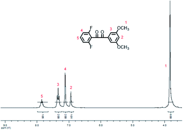
In the synthetic procedures, the preparation of 3,5-dimethoxybenzyl magnesium bromide is needed to be performed at −10 °C in a mixture solution of diethyl ether and toluene, where toluene is utilized to increase the solubility of 3,5-dimethoxybenzyl bromide, while low temperature prevents self-coupling.The chemical structure of DFDMED was characterized via 1H-NMR, IR, and GC/EI-MS. From the 1H-NMR spectrum (Fig. 1), five kinds of protons with the quantity ratio of 1![[thin space (1/6-em)]](https://www.rsc.org/images/entities/char_2009.gif) :
:![[thin space (1/6-em)]](https://www.rsc.org/images/entities/char_2009.gif) 2:2
2:2![[thin space (1/6-em)]](https://www.rsc.org/images/entities/char_2009.gif) :
:![[thin space (1/6-em)]](https://www.rsc.org/images/entities/char_2009.gif) 1:6 were confirmed, wherein a big peak at 3.83 ppm refers to the dimethoxy protons and a peak at 6.94 ppm represents the phenyl protons between two methoxy groups. This is in good accordance with the structure of DFDMED. From the IR data, the absorption bands at 1695 and 1647 cm−1 are assigned as the stretching vibrations of the C
1:6 were confirmed, wherein a big peak at 3.83 ppm refers to the dimethoxy protons and a peak at 6.94 ppm represents the phenyl protons between two methoxy groups. This is in good accordance with the structure of DFDMED. From the IR data, the absorption bands at 1695 and 1647 cm−1 are assigned as the stretching vibrations of the C![[double bond, length as m-dash]](https://www.rsc.org/images/entities/char_e001.gif) O bond, while the peaks at 1596 and 1235 cm−1 are ascribed to the vibrations of the phenyl ring and the C–F bond, respectively. The strong peaks at 1460 and 1368 cm−1 are attributed to the vibration of the C–H bond in the methoxy group. Meanwhile, the absorption bands at 855 and 671 cm−1 are assigned as the C–H out-of-plane bending vibrations for 1,3,5- and 1,2,3-substituted benzenoid structures, respectively. From the GC/EI-MS data, the peak at m/z 306.22 with the relative intensity of 6% is assigned as the molecular ion peak, which is consistent with the calculated molecular weight of 306.26. In addition, the peak at m/z 165.13 with 100% relative intensity is ascribed to the elimination of the difluorobenzoyl radical from the molecular ion species. These results prove that DFDMED has the structure proposed in Scheme 1.
O bond, while the peaks at 1596 and 1235 cm−1 are ascribed to the vibrations of the phenyl ring and the C–F bond, respectively. The strong peaks at 1460 and 1368 cm−1 are attributed to the vibration of the C–H bond in the methoxy group. Meanwhile, the absorption bands at 855 and 671 cm−1 are assigned as the C–H out-of-plane bending vibrations for 1,3,5- and 1,2,3-substituted benzenoid structures, respectively. From the GC/EI-MS data, the peak at m/z 306.22 with the relative intensity of 6% is assigned as the molecular ion peak, which is consistent with the calculated molecular weight of 306.26. In addition, the peak at m/z 165.13 with 100% relative intensity is ascribed to the elimination of the difluorobenzoyl radical from the molecular ion species. These results prove that DFDMED has the structure proposed in Scheme 1.
3.2. Characterization of the copolymers
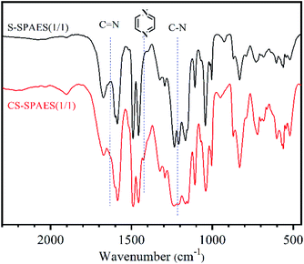
As shown in Table 1, the prepared crosslinkable copolymers bearing two pendant methoxyl groups (S-PAES(x/y)-OCH3) display highly reduced viscosities of 0.71–0.82 dL g−1, where the molar ratio of DFDPS to DFDMED is set as 1/1, 2/3, and 1/2 for x/y, respectively. Meanwhile, the copolymers have high molecular weights with Mw and Mn of 6.43–8.01 × 10⁴ g mol−1 and 4.00–4.57 × 10⁴ g mol−1 (Table S1 and Fig. S1 in the ESI†), respectively, which indicates good random co-polycondensation. The molecular weight distributions (Mw/Mn) of the copolymers are 1.32–1.58, indicating typical polycondensation. Further post-sulfonation was carried out via demethylation and nucleophilic substitution with 1,4-butane sultone to prepare the crosslinkable side-chain sulfonated copolymers S-SPAES(x/y) (Scheme 2).The structures of the copolymers S-SPAES(x/y) were confirmed via IR and 1H-NMR spectroscopy. From the IR spectrum of S-SPAES(1/1) in Fig. 2, the symmetric and asymmetric stretching vibrations of C![[double bond, length as m-dash]](https://www.rsc.org/images/entities/char_e001.gif) O in the ethanedione unit appear at 1665 cm−1, while the absorption peaks at 1040, 1065, and 1105 cm−1 are assigned to the vibration of O
O in the ethanedione unit appear at 1665 cm−1, while the absorption peaks at 1040, 1065, and 1105 cm−1 are assigned to the vibration of O![[double bond, length as m-dash]](https://www.rsc.org/images/entities/char_e001.gif) S
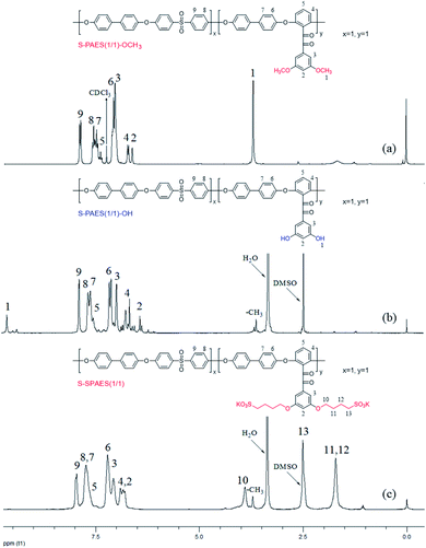
S![[double bond, length as m-dash]](https://www.rsc.org/images/entities/char_e001.gif) O in the sulfonic acid group. In addition, the peaks at 1600, 1590, and 1495 cm−1 are attributed to the vibrations of the phenyl skeleton. Fig. 3(a) and (b) demonstrate the 1H-NMR spectra of S-PAES(1/1)-OCH3 and S-PAES(1/1)-OH, respectively, while Fig. 3(c) reveals the 1H-NMR spectrum of S-SPAES(1/1). The characteristic signal at 3.71 ppm in Fig. 3(a) is ascribed to the aliphatic protons of the methoxy group in DFDMED, while the signal at 7.96 ppm is identified as the aromatic proton in DFDPS, suggesting good random co-polycondensation. After demethylation, S-PAES(1/1)-OH displays much lower characteristic methyl protons at 3.71 ppm in Fig. 3(b); meanwhile, a new signal at 9.65 ppm is identified as the hydroxyl proton. It is noted that the extent of demethylation is about 80% via quantification from the 1H-NMR spectrum. For S-SPAES(1/1), the aliphatic protons at 3.90, 2.50, and 1.70 ppm (Fig. 3(c)) indicate incorporation of pendant butanesulfonic acid groups into the side-chains of the copolymer. The other 1H-NMR spectra of the copolymers are shown in Fig. S2 and S3 in the ESI.†
O in the sulfonic acid group. In addition, the peaks at 1600, 1590, and 1495 cm−1 are attributed to the vibrations of the phenyl skeleton. Fig. 3(a) and (b) demonstrate the 1H-NMR spectra of S-PAES(1/1)-OCH3 and S-PAES(1/1)-OH, respectively, while Fig. 3(c) reveals the 1H-NMR spectrum of S-SPAES(1/1). The characteristic signal at 3.71 ppm in Fig. 3(a) is ascribed to the aliphatic protons of the methoxy group in DFDMED, while the signal at 7.96 ppm is identified as the aromatic proton in DFDPS, suggesting good random co-polycondensation. After demethylation, S-PAES(1/1)-OH displays much lower characteristic methyl protons at 3.71 ppm in Fig. 3(b); meanwhile, a new signal at 9.65 ppm is identified as the hydroxyl proton. It is noted that the extent of demethylation is about 80% via quantification from the 1H-NMR spectrum. For S-SPAES(1/1), the aliphatic protons at 3.90, 2.50, and 1.70 ppm (Fig. 3(c)) indicate incorporation of pendant butanesulfonic acid groups into the side-chains of the copolymer. The other 1H-NMR spectra of the copolymers are shown in Fig. S2 and S3 in the ESI.†
3.3. Characterization of the crosslinked copolymers
Fig. 2 shows the IR spectrum of the crosslinked sulfonated copolymer CS-SPAES(1/1). Compared to the crosslinkable S-SPAES(1/1), CS-SPAES(1/1) displays characteristic absorption bands of the quinoxaline ring at 1424 cm−1 (shoulder peak) and the characteristic stretching vibration of the C–N bond at 1220 cm−1, which indicates the formation of the quinoxaline cross-linkage. Meanwhile, the crosslinked sulfonated copolymers CS-SPAES(x/y) are insoluble in common aprotic solvents, while the crosslinkable ones have good solubility in aprotic solvents (Table 2). The solubility results further prove the formation of crosslinking after cyclo-condensation. In addition, according to the feed ratio of DAB to DFDMED (0.3/1), the maximum crosslinking degree is up to 60%.| Code | CHCl3 | DMSO | NMP | DMAc | DMF |
|---|---|---|---|---|---|
| a DMSO: dimethyl sulfoxide; NMP: 1-methyl-2-pyrrolidone; DMAc: N,N-dimethyl-acetamide; DMF: N,N-dimethylformamide; ++: soluble at room temperature; −: insoluble. | |||||
| S-SPAES(1/1) | − | ++ | ++ | ++ | ++ |
| S-SPAES(2/3) | − | ++ | ++ | ++ | ++ |
| S-SPAES(1/2) | − | ++ | ++ | ++ | ++ |
| CS-SPAES(1/1) | − | − | − | − | − |
| CS-SPAES(2/3) | − | − | − | − | − |
| CS-SPAES(1/2) | − | − | − | − | − |
3.4. Characterization of the copolymer membranes
The copolymer membranes are obtained from the solution casting method, wherein the crosslinked membranes are fabricated using cyclo-condensation reaction solutions.27,28 The membranes have good mechanical properties (Table 3), where the Young's modulus (YM), maximum stress (MS), and elongation at break (EB) are 0.92–0.97 GPa, 41–49 MPa, and 7.1–11.0% for the crosslinkable membranes S-SPAES(x/y), while they are 1.00–1.13 GPa, 45–56 MPa, and 6.3–7.5% for the crosslinked CS-SPAES(x/y), respectively. The results reveal that CS-SPAES(x/y) has slightly better mechanical properties than S-SPAES(x/y), which is ascribed to the crosslinking structure in the membranes.| Code | YM (GPa) | MS (MPa) | EB (%) |
|---|---|---|---|
| a YM: young's modulus; MS: maximum stress; EB: elongation at break. | |||
| S-SPAES(1/1) | 0.93 | 40.95 | 7.21 |
| S-SPAES(2/3) | 0.97 | 42.86 | 10.98 |
| S-SPAES(1/2) | 0.92 | 48.63 | 7.13 |
| CS-SPAES(1/1) | 1.09 | 44.61 | 6.32 |
| CS-SPAES(2/3) | 1.13 | 49.26 | 7.48 |
| CS-SPAES(1/2) | 1.00 | 55.63 | 6.62 |
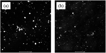
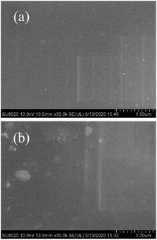
The morphologies of the membranes are shown in Fig. 4 for S-SPAES(1/1) and CS-SPAES(1/1) in the Ag+ forms, wherein the bright and dark domains in the TEM images represent the hydrophilic and hydrophobic phases, respectively. The membranes display obvious microphase separations, which is attributed to their side-chain sulfonated copolymer structures. From Fig. 4(a) and (b), CS-SPAES(1/1) shows smaller average hydrophilic domains than S-SPAES(1/1), which may be due to the restraining aggregation of the sulfonic acid groups resulting from the crosslinking. Meanwhile, the AFM images of the membranes are shown in Fig. 5(a)–(f), wherein the dark and bright domains are identified as the hydrophobic and hydrophilic phases, respectively. It was found that both S-SPAES(x/y) and CS-SPAES(x/y) exhibit good microphase separations, which is consistent with the TEM results. From Fig. 5, it is noted that the hydrophilic domain size of the uncrosslinked membrane is 3–20, 4–22, and 6–28 nm for S-SPAES(1/1), S-SPAES(2/3), and S-SPAES(1/2), respectively. The sizes of the hydrophilic domains show a slight enlargement with the increase in the sulfonated units. For the crosslinked membranes, the hydrophilic domain size is 1–8, 1–11, and 2–16 nm for CS-SPAES(1/1), CS-SPAES(2/3), and CS-SPAES(1/2), respectively. Compared to the uncrosslinked membranes, the crosslinked ones exhibit much smaller hydrophilic domains, which is attributed to their crosslinked copolymer structures. In addition, the SEM images in Fig. 6 and S4 in the ESI† reveal that the obtained crosslinked and uncrosslinked membranes have homogeneous morphologies and dense membrane surfaces.
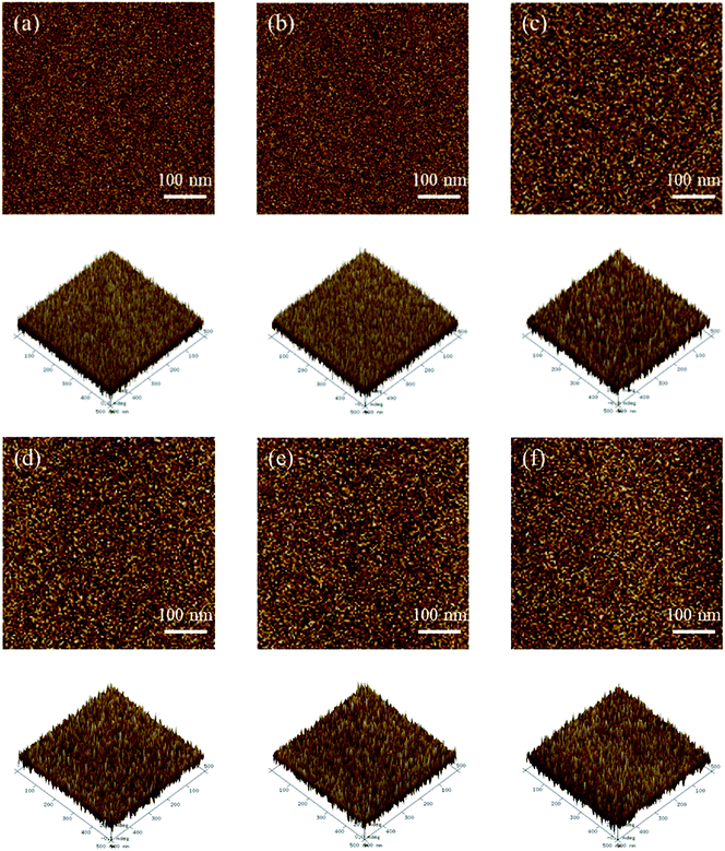 | ||
| Fig. 5 AFM images of the membranes. (a) CS-SPAES(1/1), (b) CS-SPAES(2/3), (c) CS-SPAES(1/2), (d) S-SPAES(1/1), (e) S-SPAES(2/3), and (f) S-SPAES(1/2). | ||
3.5. IEC, WU, dimensional change, and membrane stability
The basic properties of crosslinkable and crosslinked side-chain sulfonated copolymer membranes are listed in Table 4. The IEC values are calculated from a titration method, where 0.05 M NaOH solution was chosen to titrate the released proton in the soaking solution (15 wt% NaCl) containing the sample membrane and phenolphthalein was utilized as the indicator. From Table 4, it can be seen that the membranes have IECs of 1.68–2.01 mequiv. g−1 for S-SPAES(x/y) and 1.40–1.72 mequiv. g−1 for CS-SPAES(x/y), respectively, which are comparable to those of the reported membranes.10–12,15,24,25,27–30| Code | Membrane | IEC (mequiv. g−1) | WU (%) | λ | Size changea (%) | Δt/la | |||
|---|---|---|---|---|---|---|---|---|---|
| 25 °C | 80 °C | 25 °C | 80 °C | Δtc | Δlc | ||||
| a At 80 °C. | |||||||||
| S-SPAES(1/1) | BP-DFDPS/DFDMED(1/1) | 1.68 | 19.8 | 29.5 | 7 | 10 | 14.1 | 11.6 | 1.22 |
| S-SPAES(2/3) | BP-DFDPS/DFDMED(2/3) | 1.88 | 26.9 | 38.3 | 8 | 11 | 15.7 | 12.8 | 1.23 |
| S-SPAES(1/2) | BP-DFDPS/DFDMED(1/2) | 2.01 | 33.9 | 46.2 | 9 | 13 | 16.9 | 14.2 | 1.19 |
| CS-SPAES(1/1) | BP-DFDPS/DFDMED/DAB(1/1/0.3) | 1.40 | 10.1 | 20.6 | 4 | 8 | 9.3 | 8.6 | 1.08 |
| CS-SPAES(2/3) | BP-DFDPS/DFDMED/DAB(2/3/0.9) | 1.67 | 13.4 | 22.7 | 4 | 8 | 11.2 | 9.8 | 1.14 |
| CS-SPAES(1/2) | BP-DFDPS/DFDMED/DAB(1/2/0.6) | 1.72 | 15.3 | 24.9 | 5 | 8 | 12.6 | 10.4 | 1.21 |
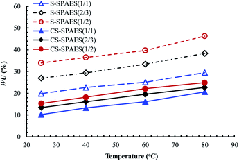
WU represents the water absorbed in the membrane, which can ensure the dissociation and transportation of the proton, as well as the construction of an interconnected ion channel. In general, a large WU contributes to enhanced proton conductivity; however, this will easily lead to excessive swelling and thus cause dimensional mismatch in fuel cell applications. From Table 4 and Fig. 7, it is observed that WU increases steadily on promoting IEC from 1.40 to 2.01 mequiv. g−1, and it is significantly enhanced with increasing temperature from 25 to 80 °C, respectively. It is noted that CS-SPAES(1/2) exhibits much lower WU (24.9%) than the crosslinkable S-SPAES(1/2) (46.2%) at 80 °C, which is attributed to its smaller IEC and crosslinking structures. In addition, CS-SPAES(1/2) has lower WU than S-SPAES(1/1) (29.5%) in spite of its slightly higher IEC, which reveals that the crosslinking restrains the relaxation of the copolymer chains in water and thus leads to a decrease in WU.
Another objective parameter related to the membrane absorbability, namely, the number of absorbed water molecules per ionic group (λ), is utilized to analyze the WU of the membranes with different IECs,12,15,25,27,28,37,38 which is calculated via equation, λ = (10 × WU)/(18 × IEC). The membranes exhibit λ values of 8–13 at 80 °C (Table 4), which is comparable to the reported main-chain SPAESs (IECs of 1.20–2.74 mequiv. g−1 and λ of 9–48)27,28,37,38 and the side-chain SPAESs (IECs of 0.88–1.70 mequiv. g−1 and λ of 8–21)12,15,25 but lower than that of Nafion 117 (λ of 19).10 The crosslinked membranes CS-SPAES(x/y) show lower λ (8) than the corresponding crosslinkable S-SPAES(x/y) (10–13), which is in accordance with the above WUs. In addition, the side-chain crosslinkable (S-SPAES(1/2)) and crosslinked membranes (CS-SPAES(1/2)) display much lower λ values than the reported main-chain reference membrane R1 (S1, λ of 27) and the corresponding crosslinked membrane R2 (CS1-1, λ of 20) with comparable IECs.28
The through-plane (Δtc) and in-plane (Δlc) membrane swelling are shown in Table 4 and Fig. 8. Similar to WU, the dimensional changes increase steadily on promoting the IEC from 1.40 to 2.01 mequiv. g−1 and they are significantly enhanced with increasing temperature from 25 to 80 °C. From Table 4, it can be seen that the membranes exhibit the anisotropic membrane swelling ratio (Δtc/Δlc) of 1.08–1.23, which suggests that the membranes display slightly larger swelling in the thickness than in the plane. This is different from the isotropic membrane swelling of the main-chain SPAES reference membranes R1 and R2.28 The difference in the membrane swelling is attributed to their side-chain sulfonated copolymer structures. The crosslinked membranes exhibit Δtc of 9.3–12.6% and Δlc of 8.6–11.6% at 80 °C, which are significantly lower than that of the crosslinkable membranes (Δtc of 14.1–16.9% and Δlc of 11.6–14.2%), suggesting the effective inhibition in the polymer chain relaxation resulting from the crosslinking structures. In addition, the side-chain S-SPAES(1/2) and CS-SPAES(1/2) exhibit much smaller dimensional changes in both the through-plane and in-plane directions than R1 (Δtc of 31% and Δlc of 29%) and R2 (Δtc of 18% and Δlc of 17%) in spite of their comparable IECs,28 which is in accordance with the above WU.
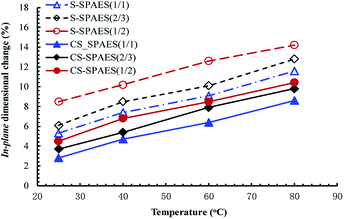 | ||
| Fig. 8 Temperature dependence of the in-plane dimensional changes for the crosslinkable and crosslinked membranes. | ||
Membrane durability under hydroxy and/or hydroperoxy radical attacks was evaluated commonly from the oxidative stability in Fenton's reagent (3 wt% H2O2 + 2 ppm Fe2SO4) at 80 °C and the elapsed time (τ), for which the membrane sheet keeps its shape in the Fenton's reagent with periodical shaking until it breaks into pieces, is chosen to represent the oxidative stability. From Table 5, the crosslinkable membranes S-SPAES(x/y) show comparable oxidative stability (τ of 100–143 min) to R1 (τ of 125 min), whereas the crosslinked membranes CS-SPAES(x/y) exhibit much higher oxidative stability (τ of 301–351 min) than R2 (τ of 260 min),28 which reveals that the side-chain crosslinked copolymer structures are more suitable for the preparation of durable membranes than the main-chain ones. This is attributed to the good microphase separation structure in the present membranes, which leads to low WU and membrane swelling, thus restricting the radical damage domains and enhancing the membrane durability. In addition, CS-SPAES(1/2) shows much higher oxidative stability (τ of 301 min) than the corresponding crosslinkable S-SPAES(1/2) (τ of 100 min) and S-SPAES(1/1) (τ of 143 min) with comparable IEC, which is due to covalent crosslinking, as well as low WU and dimensional changes. This is in agreement with the literature.22
| Code | σa (mS cm−1) | ΔEa (kJ mol−1) | τb time (min) | PMc (10−7 cm2 s−1) | φc (104 S cm−3 s−1) | |
|---|---|---|---|---|---|---|
| 25 °C | 80 °C | |||||
| a In water.b τ: oxidative stability; time: the elapsed time after which the membranes became broken.c At 32 wt% methanol solution and 25 °C. | ||||||
| S-SPAES(1/1) | 40 | 144 | 20.2 | 143 | 2.72 | 14.7 |
| S-SPAES(2/3) | 57 | 163 | 16.5 | 123 | 4.37 | 13.0 |
| S-SPAES(1/2) | 67 | 180 | 15.7 | 100 | 7.12 | 9.4 |
| CS-SPAES(1/1) | 28 | 102 | 20.5 | 351 | 1.02 | 27.5 |
| CS-SPAES(2/3) | 39 | 145 | 18.3 | 329 | 1.31 | 29.8 |
| CS-SPAES(1/2) | 46 | 157 | 18.1 | 301 | 1.64 | 28.0 |
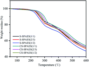
The TGA curves in Fig. 9 reveal the thermal properties of the membranes. Both S-SPAES(x/y) and CS-SPAES(x/y) exhibit three-step degradation, wherein the sulfonic acid groups, pendant alkoxy chain, and copolymer matrix decompose at 200–300 °C, 300–400 °C, and above 400 °C, respectively. High decomposition temperatures above 200 °C indicate high membrane stability for fuel cell application under common operation temperature. In addition, CS-SPAES(x/y) shows slightly higher thermal stability than S-SPAES(x/y) because of their quinoxaline-based crosslinking, which is in good agreement with the literature.27,28,37,38
3.6. Conductivity and methanol permeability
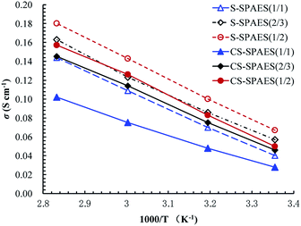
Generally, proton conductivity (σ) varies with the temperature and humidity as well as IEC and WU of the membranes. Table 5 lists the σ values in water and the apparent activation energy (ΔEa) of the conductivity, while Fig. 10 shows the temperature dependence of σ for the obtained membranes. From Table 5 and Fig. 10, it can be seen that σ enhances gradually with increasing temperature from 25 to 80 °C, and increases steadily on promoting the IEC from 1.40 to 2.01 mequiv. g−1, respectively, which is similar to WU and the dimensional changes. The σ values are 144–180 mS cm−1 (80 °C) for S-SPAES(x/y) with IECs of 1.68–2.01 mequiv. g−1 and 102–157 mS cm−1 for CS-SPAES(x/y) with IECs of 1.40–1.72 mequiv. g−1, respectively, where the larger σ values for the crosslinkable membranes are ascribed to their higher IECs and larger hydrophilic domains (Fig. 4 and 5) than those of the crosslinked ones. In addition, the apparent activation energy (ΔEa) of σ is evaluated for the membranes in the temperature range of 25–80 °C. The membranes have ΔEa values of 15.7–20.5 kJ mol−1, which is comparable to the reference membranes (8–24 kJ mol−1) with IECs of 0.88–2.74 mequiv. g−1.10,24,25,27,28,37 It is noted that the side-chain S-SPAES(1/1) and CS-SPAES(1/2) exhibit higher σ values (144 and 157 mS cm−1) than the main-chain reference membrane R3 (Table 6, σ of 120 mS cm−1) and the crosslinked R2 (σ of 141 mS cm−1) with comparable IECs; in spite of this, the σ of S-SPAES(1/2) is lower than that of R1.28 This suggests that the side-chain sulfonated copolymer structures are probably beneficial for building ion transport channels than the main-chain ones. In addition, the σ of CS-SPAES(1/2) is higher than that of S-SPAES(1/1) with comparable IEC due to its slightly higher ion concentration resulting from lower dimensional changes.| Code | Membrane | IEC (mequiv. g−1) | WUa (%) | σb (mS cm−1) | PMc (conc./temp.) (10−7 cm2 s−1) | 10−4 φ (S cm−3 s−1) | Ref. | |
|---|---|---|---|---|---|---|---|---|
| 25 °C | 80 °C | |||||||
| a Water uptake at 80 °C.b In water at 25 (or 30) and 80 °C.c At the conditions of methanol concentration (wt%) and temperature (°C) given in parentheses. | ||||||||
| S-SPAES(1/2) | 2.01 | 46.2 | 67 | 180 | 7.12 (32/25) | 9.4 | This | |
| CS-SPAES(1/2) | 1.72 | 24.9 | 46 | 157 | 1.64 (32/25) | 28.0 | This | |
| R1 | BP-SDFDPS/DFB (1/1) | 1.96 | 99 | 98 | 197 | 11.6 (32/25) | 8.4 | 28 |
| R2 | BP-SDFDPS/DFB/DAB (1/1/0.2) | 1.76 | 63 | 45 | 141 | 4.9 (32/25) | 9.2 | 28 |
| R3 | BP-SDFDPS/DFB (2/3) | 1.65 | 53 | 43 | 120 | 4.8 (32/25) | 9.0 | 28 |
| R4 | SQMPAEK-2.5 | 2.75 | 208 | 151 | 317 | 19.7 (3.2/25) | 7.7 | 39 |
| R5 | SPAEK(X9.1Y8.8) | 2.01 | 70 (90 °C) | 58 (30 °C) | 154 | 11 | ||
| R6 | BP-CBFBS/DFB/DAB (1/1/0.2) | 1.65 | 42 | 39 | 111 | 5.5 (32/25) | 7.1 | 27 |
| R7 | sPh-PESK-13 | 1.74 | 45.5 | 77 | 152 | 10 | ||
| R8 | HBSPE/SGO 0.75 | 1.75 | 43 | 385 | 8.4 (32/25) | 14 | ||
| Nafion 112 | 0.91 | (100) | 24 (10/30) | 4.2 | 40 | |||
| Nafion 117 | 0.91 | 29 | 57 | 125 | 16 (8.0/30) | 3.7 | 41 | |
The comparisons of IEC, WU, and σ values between the membranes and some reported ones are summarized in Table 6. The crosslinkable S-SPAES(1/2) displays significantly larger σ and lower WU than the side-chain poly(arylene ether) membrane R5 with comparable IEC;11 meanwhile, it shows reduced WU by about 78% and decreased σ by only about 43% than R4.39 Furthermore, the present side-chain sulfonated copolymer membranes have much higher σ but significantly lower WU than the reference main-chain ones except R1 with comparable IECs.28 These results suggest that the side-chain sulfonated copolymer structure probably contributes to the achievement of a better balance between the WU and σ via the introduction of DFDMED-based hydrophilic units into the membranes. In addition, CS-SPAES(1/2) exhibits larger or comparable σ value (157 mS cm−1) but much lower WU (24.9%) than the reported crosslinked membranes with comparable IECs (R2, R6, and R7),10,27,28 whereas its σ value and WU are significantly lower than those of R8 in spite of their comparable IECs.14
PM refers to the level of methanol crossover for PEM, which is commonly utilized to evaluate fuel crossover in the polymer electrolyte fuel cells to some extent. Meanwhile, another parameter (φ) calculated from the ratio of σ to PM is generally utilized to assess the membrane performance.25,27,28,37,38 From Tables 5 and 6, it is observed that the present side-chain sulfonated copolymer membranes show much smaller PM (1.02–7.12 × 10⁻⁷ cm2 s−1) but higher φ values (9.4–29.8 × 10⁴ S cm−3 s−1) than the representative Nafion 112 (PM of 24 × 10−7 cm2 s−1 and φ of 4.2 × 10⁴ S cm−3 s−1) and Nafion 117 (PM of 16 × 10−7 cm2 s−1 and φ of 3.7 × 10⁴ S cm−3 s−1).40,41 The S-SPAES(1/2) has lower PM (7.12 × 10⁻⁷ cm2 s−1) but higher φ (9.4 × 10⁴ S cm−3 s−1) than R1 (PM of 11.6 × 10⁻⁷ cm2 s−1 and φ of 8.4 × 10⁴ S cm−3 s−1) and R4 (PM of 19.7 × 10⁻⁷ cm2 s−1 and φ of 7.7 × 10⁴ S cm−3 s−1);28,39 this is ascribed to its low membrane swelling. However, the crosslinked membrane CS-SPAES(1/2) exhibits much lower PM (1.64 × 10⁻⁷ cm2 s−1) but significantly larger φ (28.0 × 10⁴ S cm−3 s−1) than the crosslinked R2 (PM of 4.9 × 10⁻⁷ cm2 s−1 and φ of 9.2 × 10⁴ S cm−3 s−1) and R6 (PM of 5.5 × 10⁻⁷ cm2 s−1 and φ of 7.1 × 10⁴ S cm−3 s−1),27,28 which is attributed to its low membrane swelling resulting from the side-chain sulfonated copolymer structures.
3.7. The single-cell performance
The single-cell PEMFC performance of S-SPAES(1/2) was evaluated at 60 °C at 100% RH via a Ningbo Beit fuel cell test system, as shown in Fig. 11. The maximum power density of the S-SPAES(1/2)-based fuel cell was 314.5 mW cm−2, which was comparable to R5 with same the IEC (324 mW cm−2).11 The S-SPAES(1/2)-based membrane-electrolyte assembly (MEA) had an acceptable single-cell PEMFC performance, which is ascribed to its reasonably large σ, low PM, and excellent dimensional stability. Furthermore, it is known that the optimization of MEA fabrication and the regulation of the fuel cell operating conditions tend to improve the performance of the MEA; the corresponding research is ongoing.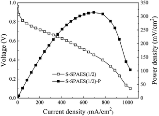 | ||
| Fig. 11 Polarization (open symbols) and power density (solid symbols) curves of the single cell based on S-SPAES(1/2) membranes at 60 °C in 100% RH condition. | ||
4. Conclusions
Herein, a new crosslinkable difluoro aromatic monomer DFDMED is developed and a series of DFDMED-based crosslinkable sulfonated copolymers was prepared via post-sulfonation. Furthermore, the crosslinked copolymers were obtained through quinoxaline-based crosslinking between S-SPAES(x/y) and DAB. The crosslinkable and crosslinked membranes generally have a higher σ than the main-chain ones because of their side-chain sulfonated copolymer structures, which are beneficial for building ion transport channels. S-SPAES(1/2) with an IEC of 2.01 mequiv. g−1 exhibits good performance, such as a high σ of 180 mS cm−1, a low PM of 7.12 × 10⁻⁷ cm2 s−1, a large φ of 9.4 × 10⁴ S cm−3 s−1, and a maximum power density of 314.5 mW cm−2, indicating its possible application prospect in PEMFCs.Conflicts of interest
There are no conflicts to declare.Acknowledgements
The authors thank the financial support by National Science Foundation Committee of China (51773112, 51873100, and 21673134), Program for Science & Technology Innovation Team of Shaanxi Province (2018TD-030), and the Fundamental Research Funds for the Central Universities (GK201801001 and GK201703030).References
- M. A. Hickner, H. Ghassemi, Y. S. Kim, B. R. Einsla and J. E. McGrath, Chem. Rev., 2004, 104, 4587–4612 CrossRef CAS PubMed.
- H. Zhang and P. K. Shen, Chem. Rev., 2012, 112, 2780–2832 CrossRef CAS PubMed.
- D. W. Shin, M. D. Guiver and Y. M. Lee, Chem. Rev., 2017, 117, 4759–4805 CrossRef CAS PubMed.
- R. Souzy and B. Ameduri, Prog. Polym. Sci., 2005, 30, 644–687 CrossRef CAS.
- S. J. Peighambardoust, S. Rowshanzamir and M. Amjadi, Int. J. Hydrogen Energy, 2010, 35, 9349–9384 CrossRef CAS.
- A. Kusoglu and A. Z. Weber, Chem. Rev., 2017, 117, 987–1104 CrossRef CAS PubMed.
- V. Mehta and J. S. Cooper, J. Power Sources, 2003, 114, 32–53 CrossRef CAS.
- M. Adamski, T. J. G. Skalski, S. Xu, M. Killer, E. M. Schibli, B. J. Frisken and S. Holdcroft, Polym. Chem., 2019, 10, 1668–1685 RSC.
- J. Li, F. Bu, C. Ru, H. Jiang, Y. Duan, Y. Sun, X. Pu, L. Shang, X. Li and C. Zhao, J. Mater. Chem. A, 2020, 8, 196–206 RSC.
- C. Wang, Y. Zhou, B. Shen, X. Zhao, J. Li and Q. Ren, Polym. Chem., 2018, 9, 4984–4993 RSC.
- K. H. Lee, J. Y. Chu, A. R. Kim and D. J. Yoo, ACS Appl. Mater. Interfaces, 2018, 10, 20835–20844 CrossRef CAS PubMed.
- Y. Lu, X. Zhang, X. Yan, Z. Hu and S. Chen, J. Membr. Sci., 2018, 555, 45–55 CrossRef CAS.
- F. Ahmed, S. C. Sutradhar, T. Ryu, H. Jang, K. Choi, H. Yang, S. Yoon, M. M. Rahman and W. Kim, Int. J. Hydrogen Energy, 2018, 43, 5374–5385 CrossRef CAS.
- D. Liu, J. Peng, Z. Li, B. Liu and L. Wang, J. Power Sources, 2018, 378, 451–459 CrossRef CAS.
- C. Jin, X. Zhu, S. Zhang and S. Li, Polymer, 2018, 148, 269–277 CrossRef CAS.
- J. Yang, H. Jiang, L. Gao, J. Wang, Y. Xu and R. He, Int. J. Hydrogen Energy, 2018, 43, 3299–3307 CrossRef CAS.
- N. Anahidzade, A. Abdolmaleki, M. Dinari, K. Firouz Tadavani and M. Zhiani, J. Membr. Sci., 2018, 565, 281–292 CrossRef CAS.
- K. Kim, P. Heo, W. Hwang, J.-H. Baik, Y.-E. Sung and J.-C. Lee, ACS Appl. Mater. Interfaces, 2018, 10, 21788–21793 CrossRef CAS PubMed.
- P. Muthuraja, S. Prakash, V. M. Shanmugam, S. Radhakrsihnan and P. Manisankar, Int. J. Hydrogen Energy, 2018, 43, 4763–4772 CrossRef CAS.
- S. Barati, M. Abdollahi, B. Khoshandam and M. Mehdipourghazi, Int. J. Hydrogen Energy, 2018, 43, 19681–19690 CrossRef CAS.
- T. Ryu, H. Jang, F. Ahmed, N. S. Lopa, H. Yang, S. Yoon, I. Choi and W. Kim, Int. J. Hydrogen Energy, 2018, 43, 5398–5404 CrossRef CAS.
- K. Kim, P. Heo, J. Han, J. Kim and J.-C. Lee, J. Power Sources, 2018, 401, 20–28 CrossRef CAS.
- K. Wang, L. Yang, W. Wei, L. Zhang and G. Chang, J. Membr. Sci., 2018, 549, 23–27 CrossRef CAS.
- J. Aboki, B. Jing, S. Luo, Y. Zhu, L. Zhu and R. Guo, ACS Appl. Mater. Interfaces, 2018, 10, 1173–1186 CrossRef CAS PubMed.
- C. Liu, Z. Wu, Y. Xu, S. Zhang, C. Gong, Y. Tang, D. Sun, H. Wei and C. Shen, Polym. Chem., 2018, 9, 3624–3632 RSC.
- X. Chen, K. Chen, P. Chen, M. Higa, K.-I. Okamoto and T. Hirano, J. Polym. Sci., Part A: Polym. Chem., 2010, 48, 905–915 CrossRef CAS.
- X. Chen, P. Chen, Z. An, K. Chen and K. Okamoto, J. Power Sources, 2011, 196, 1694–1703 CrossRef CAS.
- P. Chen, X. Chen, Z. An, K. Chen and K. Okamoto, Int. J. Hydrogen Energy, 2011, 36, 12406–12416 CrossRef CAS.
- J. Kerres, A. Ullrich, F. Meier and T. Häring, Solid State Ionics, 1999, 125, 243–249 CrossRef CAS.
- J. Kerres, W. Zhang and T. Haering, J. New Mater. Electrochem. Syst., 2004, 7, 299–309 CAS.
- S. D. Mikhailenko, K. Wang, S. Kaliaguine, P. Xing, G. P. Robertson and M. D. Guiver, J. Membr. Sci., 2004, 233, 93–99 CrossRef CAS.
- S. Gu, G. He, X. Wu, Y. Guo, H. Liu, L. Peng and G. Xiao, J. Membr. Sci., 2008, 312, 48–58 CrossRef CAS.
- J. Fang, F. Zhai, X. Guo, H. Xu and K.-i. Okamoto, J. Mater. Chem., 2007, 17, 1102–1108 RSC.
- S. Zhong, X. Cui, H. Cai, T. Fu, C. Zhao and H. Na, J. Power Sources, 2007, 164, 65–72 CrossRef CAS.
- F. C. Ding, S. J. Wang, M. Xiao, X. H. Li and Y. Z. Meng, J. Power Sources, 2007, 170, 20–27 CrossRef CAS.
- S. Feng, Y. Shang, X. Xie, Y. Wang and J. Xu, J. Membr. Sci., 2009, 335, 13–20 CrossRef CAS.
- P. Chen, X. Chen and Z. An, J. Appl. Polym. Sci., 2012, 124, E278–E289 CrossRef CAS.
- P. Chen, X. Chen and Z. An, Polym. Bull., 2012, 68, 1369–1386 CrossRef CAS.
- L. Zhang, G. Zhang, C. Zhao, Z. Liu, H. Jiang, S. Xu, M. Li, D. Xu and H. Na, Int. J. Hydrogen Energy, 2013, 38, 12363–12373 CrossRef CAS.
- K.-i. Okamoto, Y. Yin, O. Yamada, M. N. Islam, T. Honda, T. Mishima, Y. Suto, K. Tanaka and H. Kita, J. Membr. Sci., 2005, 258, 115–122 CrossRef CAS.
- D. S. Kim, G. P. Robertson, Y. S. Kim and M. D. Guiver, Macromolecules, 2009, 42, 957–963 CrossRef CAS.
Footnote |
| † Electronic supplementary information (ESI) available. See DOI: 10.1039/d0ra02987d |
| This journal is © The Royal Society of Chemistry 2020 |

