
 Open Access Article
 This Open Access Article is licensed under a Creative Commons Attribution-Non Commercial 3.0 Unported Licence
Enhanced performance of lithium–sulfur batteries based on single-sided chemical tailoring, and organosiloxane grafted PP separator†
Haifeng Zhou,
Qunli Tang*,
Qianer Xu,
Yan Zhang,
Cong Huang,
Yali Xu,
Aiping Hu and
Xiaohua Chen *
*
College of Materials Science and Engineering, Hunan University, Hunan Province Key Laboratory for Spray Deposition Technology and Application, Changsha 410082, P. R. China. E-mail: tangqunli@hnu.edu.cn; xiaohuachen@hnu.edu.cn
First published on 12th May 2020
Abstract
Even after a decade of research and rapid development of lithium–sulfur (Li–S) batteries, the infamous shuttle effect of lithium polysulfide is still the major challenge hindering the commercialization of Li–S batteries. In order to further address this issue, a functionalized PP separator is obtained through selective single-sided chemical tailoring, and then organosiloxane fumigation grafting. During the charge–discharge process, the grafted functional groups can effectively block the transportation of the dissolved polysulfides through strong chemical anchoring, inhibit the shuttle effect and greatly enhance the cycle stability of the Li–S battery. Interestingly, the specially designed single-sided enlarged channel structure formed by chemical tailoring can well accommodate the deposition with intermediate polysulfides on the separator surface toward the cathode chamber, resulting in enhanced initial discharge capacity and rate performance. Compared to the battery assembled with PP, the Li–S battery employing the separator grafted with a 3-ureidopropyltrimethoxysilane (PP–Ox−–U) displays better electrochemical performance. Even at 2C, it can still deliver a high capacity of 786 mA h g−1, and retain a capacity of 410 mA h g−1 with a low capacity fading of 0.095% per cycle over 500 cycles. This work provides a very promising and feasible strategy for the development of a special functionalization PP separator for Li–S batteries with high electrochemical performance.
Introduction
Lithium–sulfur batteries with a mass energy density up to 500 W h kg−1 are the most promising battery systems to meet the requirements of higher energy density.1,2 In the past decade, rechargeable Li–S batteries have been widely studied, and the relevant research has mainly focused on solving the following three problems: (1) the insulating nature of Li2S/lithium polysulfide/sulfur, (2) the large mass density difference between sulfur (2.079 g cm−3) and lithium polysulfide (1.66 g cm−3) results in serious volume expansion (∼80%) with the lithiation/delithiation process; (3) the polysulfide shuttle between cathode and anode leads to irreversible capacity fading and low coulombic efficiency. These underlying factors cause low initial discharge capacity, rate performance and poor cycle stability of Li–S batteries. It is well known that great successes have been achieved in improving the conductivity and accommodating the volume expansion of S cathode via utilizing various conductive skeleton matrixes with stress-relief buffer structures.3–5To tackle the “shuttle effect”, over the past decades, researchers have conducted in-depth research.6–8 Preventing the diffusion of polysulfides into electrolyte is a major research strategy. The effect of inhibiting the “shuttle effect” depends on the design of cathode matrix microstructure and the composition and functional modification of cathode materials. Cathode materials with different components, including carbon materials,9,10 metallic compounds4,11 and conductive polymers,12,13 as well as cathode materials with different structures, such as mesoporous, hierarchical porous, sandwich-type architecture, hollow, and core–shell structure, have been widely investigated as S host matrices, and significant progress has been made in suppressing the “shuttle effect” of polysulfides.9,14–16 In principle, these host materials play the role of polysulfides immobilization mainly through the diffusion restriction of physical confinement structures or/and strong chemical anchoring. However, from the reaction kinetics process, the conversion between S8 and Li2S2/Li2S is not completed instantaneously during the cycle process. The presence and existence of polysulfides in cathodes are inevitable, and their duration is mainly controlled by the current density of charge and discharge. Because of the existence of dissolved polysulfides in the cathode matrices, there must be a concentration gradient at the interface between cathode and electrolyte, which forces polysulfides to leave cathode host. Obviously, based on the cathode material strategy, it is hardly possible to fundamentally solve the shuttle effect. Therefore, it is of great significance to block dissolved polysulfides entering the negative chamber. Functionalization of separator makes it feasible to prevent polysulfides from entering the negative chamber.
According to recent reports, adding an interlayer17–19 between the separator and the cathode or a coating layer20–22 on the separator surface facilitates to effectively block polysulfides entering into the negative electrode chamber by changing the diffusion path of polysulfides. Among them, functionalized carbon-based interlayer possesses many virtues since its physical barrier and good electrical conductivity. For instance, Song et al. designed an ultra-thin continuous Li4Ti5O12 (LTO) layer coated carbon nanofiber (CNF) between cathode and separator as an intermediate layer. LTO–CNF membrane surface defects were used to construct a large number of adsorption sites which effectively anchor the polysulfides. Utilizing this LTO–CNF interlayer, the lithium–sulfur battery presents a superior electrochemical performance.19 Nahid et al. designed a polypropylene (PP) separator coated with MoO3 nanobelts (MNBs). The membrane can inhibit the polysulfides shuttling and facilitate ionic transfer by the formation of Li2Sn–MoO3 during charging and discharging, thus delivering a substantially high initial discharge capacity and extraordinary cycle life.21 However, no matter what coating or interlayer strategy is adopted, because they are usually carbon materials or/and composite materials of polar inorganic materials, the extra mass and volume will inevitably reduce the energy density of battery system and hinder the commercialization. Also, the additional contact interfaces caused by the interlayer or coating will affect the internal resistance performance of the battery, especially for the surface coating, which usually covers or even blocks the separator channel, affecting the transportation of lithium ions. Recently, the research strategy on preventing shuttle effect by modifying the separator itself has been reported.23,24 For example, Ding's group elaborately constructed a new polysulfide blocker by grafting polyacrylic acid (PAA) on the surface of pre-activated polypropylene (PP) separator through ultraviolet polymerization. The PP membrane grafted with PAA (PP–g–PAA) can transfer lithium-ion. Still, the electrostatic repulsion of polysulfide anions greatly inhibits the shuttle effect of soluble polysulfide lithium and prolongs the cycle life of the lithium–sulfur battery.23 Wei's group delicately designed a novel separator structure by additionally introduced tertiary amine layer on the pre-activated PP through ultraviolet radiation. The tertiary amine functional group plays a vital role as “polysulfide tongs”, which can selectively capture and release dissolved polysulfides, thereby enhancing specific capacity and charge transfer.24 Therefore, the functionalized modification of the separator itself is an effective method to improve the performance of lithium–sulfur batteries.
Different from the previous reports on separator modification, in this work, the separator grafted with the 3-ureidopropyltrimethoxysilane was fabricated through PP single-sided chemical tailoring. The grafted functional molecule containing rich active groups of terminal amine and silicon hydroxyl can effectively block polysulfides entering into anode chamber through chemically anchoring. Compared to the pristine channel structure of PP, the unique single-sided enlarged channel structure formed by chemical tailoring can well accommodate the deposition with intermediate polysulfides on the separator surface toward cathode chamber. Moreover, the significant improvement of the wettability of the separator in a polar solvent is helpful to reduce the interfacial resistance and improve the transportation of lithium-ion, especially at high current density. Compared to the coating or interlayer strategy, the strategy of in situ grafting organosiloxane through the separator itself functionalization does not affect the energy density of the battery system. The results exhibit that the lithium–sulfur battery employing this functionalized separator has significantly improved cycle stability, initial discharge capacity, and high rate performance. What's more, the working mechanism of chemical anchoring of polysulfides by the functionalized PP separator has been investigated in detail.
Experimental
Materials
Sulfuric acid (H2SO4, 98%, Sinopharm), potassium permanganate (KMnO7, ≥99.5%, Sinopharm) 3-ureidopropyltrimethoxysilane (SCA-U60M, chemical purity, Nanjing Nengde, in China), 3-mercaptopropyltriethoxysilane (SCA-S89E, chemical purity, Nanjing Nengde, in China), lithium sulfide (Li2S, ≥99.9%, Aladdin), ketjen black EC 600 (KB, ≥99.9%, Kluthe).Preparation of functionalized separator
The functionalized separator was prepared by single-sided chemical tailoring in the oxidative solution and grafting in the organosiloxane vapor. Specifically, the commercial polypropylene membrane was put into a 500 ml beaker and ultrasonically rinsed with distilled water to remove the surface dust and stains. Then, PP was fixedly placed onto the mixture solution of 250 ml sulfuric acid solution (8 M) and 6.5 g potassium permanganate at a mass ratio of 30![[thin space (1/6-em)]](https://www.rsc.org/images/entities/char_2009.gif) :1, and solution under the bottom was magnetically stirred, mixed evenly. After heated at 50 °C for 1 h, the separator was taken out, repeatedly washed with dilute sulfuric acid and deionized water to remove the residual manganese ions on the separator surface and dried at 60 °C for 0.5 h. Finally, the as-prepared separator (PP–Ox−) was placed into a 250 ml sealed beaker with 1 ml 3-ureidopropyltrimethoxysilane, and fumigated at 70 °C for 10 h to obtain the functionalized separator (PP–Ox−–U). For comparison, the PP–Ox−–S–H was obtained using 3-mercaptopropyltriethoxysilane.
:1, and solution under the bottom was magnetically stirred, mixed evenly. After heated at 50 °C for 1 h, the separator was taken out, repeatedly washed with dilute sulfuric acid and deionized water to remove the residual manganese ions on the separator surface and dried at 60 °C for 0.5 h. Finally, the as-prepared separator (PP–Ox−) was placed into a 250 ml sealed beaker with 1 ml 3-ureidopropyltrimethoxysilane, and fumigated at 70 °C for 10 h to obtain the functionalized separator (PP–Ox−–U). For comparison, the PP–Ox−–S–H was obtained using 3-mercaptopropyltriethoxysilane.
Preparation of ketjen black/S composite
The KB/S composite was prepared by a simple melt-diffusion method. Specifically, 0.15 g sulfur powder and 0.1 g ketjen black EC 600 were mixed with a mass ratio of 3:2, and then sealed in a weighing bottle. Finally, the composite was heated at 155 °C for 12 h to melt sulfur into the ketjen black and cooled naturally.
Cell assembly and electrochemical measurements
The electrochemical properties of all samples were carried out by CR2025 coin-type batteries. The mixture of the active material (80 wt%), polyvinylidene fluoride (10 wt%) and Super P (10 wt%) was added into N-methyl pyrrolidone (NMP) solvent to form a homogeneous slurry. The obtained slurry was then coated onto an aluminium foil using a doctor blade and dried in a vacuum oven at 55 °C for 12 h. The loading of electrode materials (KB/S) is 1.44 mg cm−2. The cathode pole piece was punched into disks by a buckle machine, and the diameter is 16 mm. The sulfur loading is around 0.43 mg cm−2. The batteries were assembled in an argon-filled MiKROUNA glove box, using KB/S as the cathode and lithium foil as the counter electrode. 1 M bis(trifluoromethanesulfonyl)imide lithium (LiTFSI) and 0.1 M LiNO3 in a mixed solution of dimethoxyethane (DME) and 1,3-dioxolane (DOL) (volume ratio of 1:1) were used as the electrolyte. The amount of electrolyte in a single cell is 40 μL. The celgard 2300 (PP), PP–Ox−, PP–Ox−–U and PP–Ox−–S–H separators were used respectively. Galvanostatic charge and discharge measurements were conducted between 1.5 V and 3.0 V on a land CT2001A battery test system (Wuhan, China). Electrochemical impedance spectroscopy (EIS) measurements were performed on an electrochemical workstation (CHI660E) at an open-circuit voltage over the frequency range from 0.01 Hz to 1 MHz with an amplitude of 5 mV. Cyclic voltammetry (CV) measurement from 1.5 V to 3.0 V (vs. Li/Li+) was carried out on the CHI660E at a scanning rate of 0.1 mV s−1.
Preparation of lithium polysulfide (Li2S6) solution
The 1 mmol Li2S6 solution was prepared by reacting commercial sulfur and Li2S in a 5:1 (molar ratio) in DOL and DME (volume ratio of 1:1). The solution was stirred at 50 °C for 24 h. All procedures were performed in an argon-filled glove box.
Materials characterization
The crystal structure of the cathode sample was characterized using powder X-ray diffraction (XRD, Cu Kα radiation, 0.15418 nm). The XRD patterns were performed in the 2θ range of 10–80°. The morphology of all samples was observed on a Hitachi S-4800 with a 5 kV field emission scanning electron microscope equipped with an energy dispersive spectrometer device (EDS). X-ray photoelectron spectroscopy (XPS) analysis was conducted using a Thermo EscaLab 250 Xi+ spectrometer, employing non-monochromatic Al Kα as the X-ray excitation source. The sulfur content was determined on an HCT-4 thermo-gravimetric analyzer under an N2 atmosphere at a heating rate of 10 °C min−1 from room temperature to 600 °C. FTIR spectra were obtained by FTIR spectrometer (Nicolet iS50) in the range of 4000–500 cm−1. The wettability of the separators to water was measured by contact angle measuring instrument JC2000D2 (RT-400).Results and discussion
The functionalized PP separator was prepared by using organosiloxane as grafting functional molecule. As illustrated in Scheme 1, firstly, PP is chemically tailored by the single-side in the oxidative solution at 50 °C for 1 h. Then, the as-prepared separator (PP–Ox−) was washed with dilute sulfuric acid and distilled water and dried. Finally, the separators grafted with organosiloxanes (PP–Ox−–U and PP–Ox−–S–H) were fabricated by placing the PP–Ox− in a sealed beaker containing organosiloxane vapor at 70 °C for 10 h.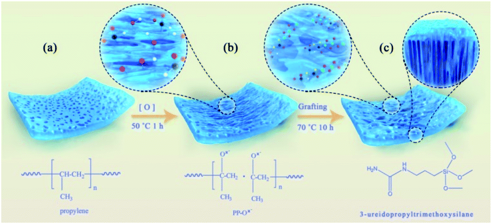 | ||
| Scheme 1 The preparation process of the functionalized separator. | ||
The morphology of all samples was observed by the scanning electron microscopy (SEM). As shown in Fig. 1a, the untreated PP separator exhibits typical monoaxial stretched surface morphology with elliptical porous. After oxidation, the surface structure of the separator PP–Ox− changed obviously and showed a significantly enlarged pore structure as compared to that of PP (Fig. 1b). As indicated by the red closed loop in Fig. 1a and b, the enlargement of the pore size is mainly caused by the fraction of PP fibers along the stretching direction under the oxidation conditions. Obviously, the strong stress positions applied to PP fibers by mechanical stretching are the most easily fractured and modified by oxidation. In addition, the water contact angle of the PP–Ox− decreases to 43.32° because of the introduction of hydrophilic oxygen-containing groups, while the untreated PP shows a contact angle of 113.49° (insert in Fig. 1a and b). In order to ensure the single-sidedness of chemical tailoring and the insulation of modified separator, the oxidation treatment occurs only on one side of the separator. Fig. 1c is a cross-sectional view of the PP–Ox−, showing that the oxidation depth is about 12 μm (PP total thickness is 25 μm). Compared with the PP–Ox−, the separator grafted with organosiloxane (PP–Ox−–U) shows a slightly decreased pore size and a bit increased fiber diameter (see in Fig. 1d). To be more specific, the surface roughness of PP fibers increases obviously, accompanied by a significantly uniform dense distribution of point matter (as indicated by arrows). These observed phenomena can reasonably be inferred from the successful grafting of organosiloxane into the PP–Ox−. The similar result can be observed on the sample PP–Ox−–S–H (Fig. 1f). As shown in Fig. 1e, EDS mapping further proves that C, N, O and Si elements are evenly distributed on the separator PP–Ox−–U. The water contact angle of the PP–Ox−–U is 91.49°, which is bigger than that of the PP–Ox− (insert in Fig. 1d). The difference of contact angle may be the increase of PP–Ox−–U surface roughness and the modification of different covering groups.
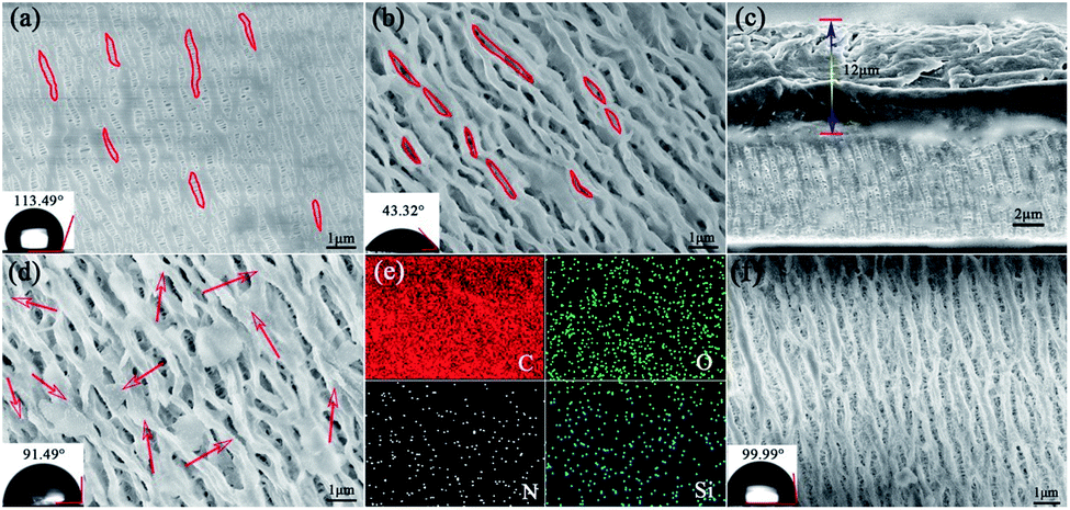 | ||
| Fig. 1 SEM images of (a) PP, (b) PP–Ox−, (c) cross-section view of PP–Ox−, (d) SEM image and (e) elemental mapping of PP–Ox−–U, and (f) SEM image of PP–Ox−–S–H. | ||
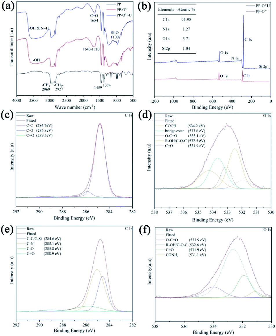
Fourier-transform infrared spectroscopy (FT-IR) was used to characterize the functionalization of organosiloxane on the separator. From Fig. 2a, the PP separator has four main characteristic peaks in the range of 2800–3000 cm−1. The peaks near 2969 cm−1 and 2874 cm−1 are asymmetric and symmetric stretching vibration of –CH3 respectively, while the peaks at 2927 cm−1 and 2840 cm−1 are caused by asymmetric and symmetric stretching vibration of –CH2 in the main chain of polypropylene.25 In comparison with PP, a very wide peak appears between 3000–3600 cm−1 after pre-oxidation treatment (PP–Ox−), which is due to the presence of hydroxyl groups. Besides, some new peaks are shown in the region 1640–1710 cm−1, which are attributed to the carbonyl groups in ketones, and carboxylic acids.26 After grafting organosiloxane, the two additional peaks at 1100 cm−1 and 1654 cm−1 appear, which are related to Si–O and C![[double bond, length as m-dash]](https://www.rsc.org/images/entities/char_e001.gif) O bands of the organosiloxane.27 In addition, the N–Hx peaks should be located in 3000–3500 cm−1, which may overlap with –OH. To further confirm the successful grafting of organosiloxane and analyze the possible grafting ways, the X-ray photoelectron spectroscopies (XPS) of the PP–Ox− and PP–Ox−–U were implemented. In Fig. 2b, XPS full-spectrum analysis of the PP–Ox−–U found N 1s and Si 2p peaks compared to that of the PP–Ox− in Fig. 2c and atomic contents were 1.27% and 1.04%, respectively. Also, the C 1s spectrum exhibits two peaks at the binding energies of 285.1 and 284.6 eV (Fig. 2e), which are ascribed to C–N, C–C/C–Si bonds in organosiloxane.26,28,29 Fig. 2d shows the O 1s high-resolution spectrum of the PP–Ox−. It can be seen that the carbon skeleton of the membrane after oxidation treatment was introduced into rich oxygen-containing functional groups including carboxylic acid, hydroxyl groups, ketone and so on, which are consistent with the peaks at 1640–1710 cm−1 in FT-IR spectrum of the PP–Ox− (Fig. 2a). These oxygen-containing functional groups can undergo esterification and amino acid reaction with amino groups and silicon hydroxyl groups in organosiloxane,30 which can be confirmed by the presence of ester groups at 533.9 eV and amide groups at 531.1 eV in O 1s spectrum of the PP–Ox−–U (Fig. 2f).31 Base on the above analysis, it is reasonable to believe that organosilane was successfully grafted onto/into the separator.
O bands of the organosiloxane.27 In addition, the N–Hx peaks should be located in 3000–3500 cm−1, which may overlap with –OH. To further confirm the successful grafting of organosiloxane and analyze the possible grafting ways, the X-ray photoelectron spectroscopies (XPS) of the PP–Ox− and PP–Ox−–U were implemented. In Fig. 2b, XPS full-spectrum analysis of the PP–Ox−–U found N 1s and Si 2p peaks compared to that of the PP–Ox− in Fig. 2c and atomic contents were 1.27% and 1.04%, respectively. Also, the C 1s spectrum exhibits two peaks at the binding energies of 285.1 and 284.6 eV (Fig. 2e), which are ascribed to C–N, C–C/C–Si bonds in organosiloxane.26,28,29 Fig. 2d shows the O 1s high-resolution spectrum of the PP–Ox−. It can be seen that the carbon skeleton of the membrane after oxidation treatment was introduced into rich oxygen-containing functional groups including carboxylic acid, hydroxyl groups, ketone and so on, which are consistent with the peaks at 1640–1710 cm−1 in FT-IR spectrum of the PP–Ox− (Fig. 2a). These oxygen-containing functional groups can undergo esterification and amino acid reaction with amino groups and silicon hydroxyl groups in organosiloxane,30 which can be confirmed by the presence of ester groups at 533.9 eV and amide groups at 531.1 eV in O 1s spectrum of the PP–Ox−–U (Fig. 2f).31 Base on the above analysis, it is reasonable to believe that organosilane was successfully grafted onto/into the separator.
 | ||
| Fig. 2 (a) FT-IR spectra of PP, PP–Ox− and PP–Ox−–U, (b) XPS full-spectra of PP–Ox− and PP–Ox−–U, XPS high-resolution spectra of (c and e) C 1s and (d and f) O 1s before and after cycling, respectively. | ||
To investigate the influence of separator modification on the battery performance, the electrochemical performance of Li–S batteries with different separators was evaluated by using KB/S composite as the cathode and Li foil as the anode. The S content in KB/S composite is 59.65 wt% measured by thermo-gravimetric analysis (TG) (Fig. S1, ESI†), which is accordant to the proportion of raw materials. The specific research results are illustrated as follows:
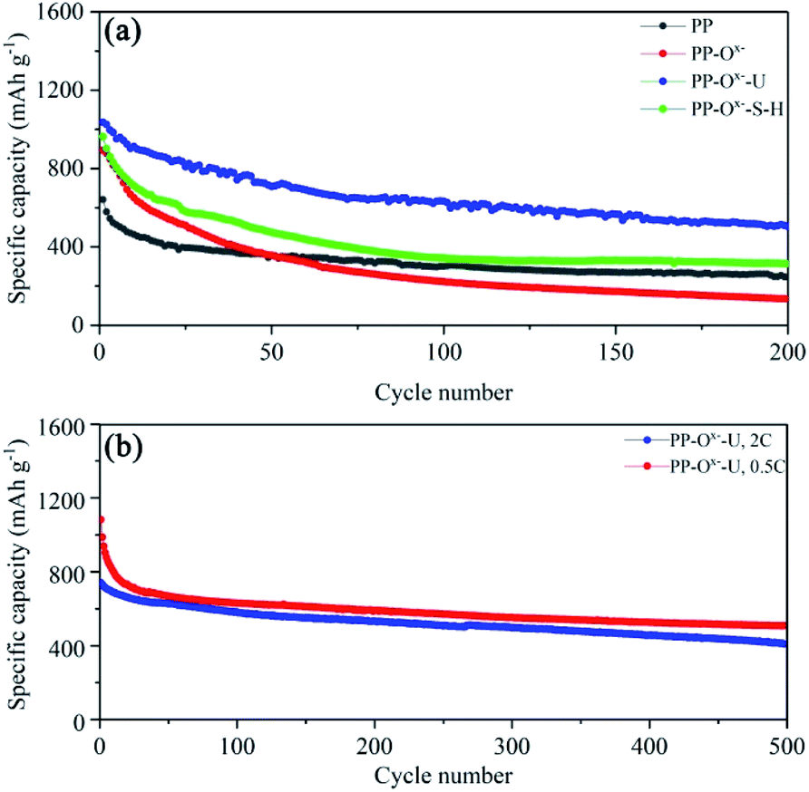
Fig. 3a displays the cycle performance of lithium–sulfur batteries with various separators. At 0.2C, the initial discharge specific capacity of the battery with PP is 616 mA h g−1, while that with the PP–Ox− is 866 mA h g−1. However, at the same current density, the battery with PP–Ox−–U shows an initial discharge specific capacity of up to 1025 mA h g−1. After 200 cycles, the capacities of the batteries with PP and the PP–Ox− quickly fade to 290 and 133 mA h g−1 respectively, while that with PP–Ox−–U possesses a highest reversible capacity of 513 mA h g−1. The main reason may be that the introduction of oxygen-containing functional groups improves the wettability of the separator (PP–Ox−). On the one hand, it accelerates the diffusion of lithium ions, displaying high initial discharge capacity, but on the other hand, it also speeds up the migration of polysulfide ions to the anode electrode, resulting in the poor cycle stability of battery with PP–Ox− after 50 cycles. When the separator grafted with organosiloxane is introduced, the battery with PP–Ox−–U shows excellent cycle stability, which may be attributed to the effective inhibition of amine and silicon hydroxyl groups on the migration of polysulfides. In addition, a similar result can be concluded on the sample PP–Ox−–S–H, which exhibits the higher initial capacity of 962 mA h g−1 than PP and maintains the higher capacity of 314 mA h g−1 after 200 cycles. It is noted that the performance difference between battery with the PP–Ox−–U and that with the PP–Ox−–S–H is due to the different molecular structure of organosiloxane. Anyhow, both are better than PP and PP–Ox−. The detailed electrochemical behavior of the batteries with PP and the PP–Ox−–U separators was further studied by cyclic voltammetry (CV) (Fig. S2†). Given the high capacity of the battery with PP–Ox−–U, the long cycles were further tested at 0.5C and 2C (Fig. 3b). At 0.5C, the Li–S battery with PP–Ox−–U can display an initial capacity of 1037 mA h g−1, and it can still maintain a high capacity of 510 mA h g−1 after 500 cycles (a low decay ratio of 0.101% per cycle). It is worth mentioning that the battery with PP–Ox−–U can also deliver a high capacity of 786 mA h g−1 even at 2C. After 500 cycles, it can retain the capacity of 410 mA h g−1 (decay ratio of 0.095% per cycle). The excellent cycling stability benefits from the grafting of organosiloxane containing amine and silanol functional groups, which can effectively intercept and entrap the migrating polysulfides during the cycling.
 | ||
| Fig. 3 Cycle performance of (a) all the samples at 0.2C, (b) PP–Ox−–U at 0.5 and 2C. | ||
To further elucidate the interaction of the PP–Ox−–U with the polysulfides, the XPS spectra of PP–Ox−–U before and after cycling were shown in Fig. 4. As depicted in Fig. 4a, the signal of sulfur is clearly detected in the XPS full-spectrum of the PP–Ox−–U after cycling, revealing the adsorption of the sulfur species on the separator. Moreover, the splitting of S 2p peaks at 162.2–168.6 eV (Fig. 4b) is rationally attributed to the varying of the complex chemical environment of sulfur after being anchored by organosiloxane.32,33 Specifically, the chemical interaction between grafted organosiloxane and polysulfides was further ascertained by the high-resolution XPS spectra of N 1s and Si 2p before and after cycling. Before cycling, N 1s spectrum of the PP–Ox−–U can be fitted to two peaks at the binding energies of 399.9 and 401.6 eV (Fig. 4c), corresponding to the –NH and –N–C bonds of amides, respectively.28,29 After cycling, the shift of N 1s peaks to lower a binding energies of 399.5 eV and 400.2 eV and appearance of a new peak at 398.8 eV (Fig. 4e) suggest that a new local environment (–NH2) of N was formed after interacting with sulfur species.34,35 This can be ascribed to the Lewis acid–base interaction, which involves unoccupied orbitals of the surface N atom and the electronegative polysulfides.24 Furthermore, a pronounced peak at 102.4 eV in the Si 2p spectrum, which corresponds to the bonding energy of C–Si–O, can be observed (Fig. 4d). After cycling, the splitting of Si 2p peaks shows two regions at 102.0 and 102.6 eV (Fig. 4f), which are the bonding of C–Si–O and Si–O to anchor polysulfides.36,37 The above analysis results are consistent with those of the S 2p. The XPS results are summarized insert in Fig. 4a, showing the element content of the PP–Ox−–U separator after cycling. Based on the above analysis, it can be concluded that the silanol and amide groups contained in the PP–Ox−–U separator have a synergistic effect, which can grasp polysulfides, relieve the shuttle effect, and improve the cycling stability of the Li–S battery.
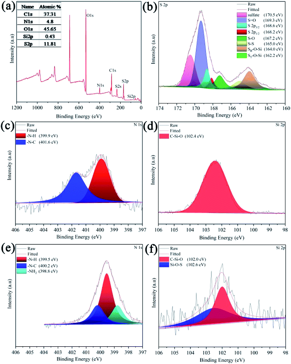 | ||
| Fig. 4 (a) XPS full-spectrum of PP–Ox−–U after cycling, (b) S 2p, XPS high-resolution spectra of (c and e) N 1s, and (d and f) Si 2p before and after cycling, respectively. | ||
To intuitively observe that polysulfides are effectively inhibited, the visualized H-type glass device with PP (top) and the PP–Ox−–U separators (bottom) were installed to examine the behavior of S62− transmission in a simulated environment within the Li–S battery during cycling (in Fig. 5). The DOL/DME solvent with and without Li2S6 (0.5 M) was injected into the left and right chamber, respectively. With PP separator, the right chamber of the device turns yellow after 30 min; subsequently, the color gradually deepens as time goes, and finally it turns brownish-yellow after 120 min (Fig. 5a–d), which can be attribute to the yellow polysulfides gradually passing through the separator from left chamber to right chamber. While with the PP–Ox−–U separator, at the same conditions, even after 120 min, no visible diffusion phenomenon of polysulfide species was observed from the H-type device (Fig. 5e–h), clearly proving that the PP–Ox−–U separator can effectively prevent the penetration of soluble polysulfide species and indicating good polysulfides blocking ability. Besides, the batteries with PP and the PP–Ox−–U are disassembled after 500 cycles. Yellow sulfur species can be observed on both sides of PP (top in Fig. 6a). Notably, the PP–Ox−–U surface facing the cathode turns yellow. However, on the PP–Ox−–U surface facing the anode, no apparent yellow sulfur species were seen, which benefits from preventing the shuttle of polysulfides (bottom in Fig. 6a). Further the SEM images of PP and the PP–Ox−–U separators facing the cathode side after 500 cycles were shown in Fig. 6b and c, respectively. It can be obviously observed that mass sulfur species accumulate on the PP surface, and most of the pores were covered (Fig. 6b). However, many macropores were still seen on the PP–Ox−–U surface, and a few mass sulfur species gather on the surface (Fig. 6c). The main reason is that the pore structure of PP–Ox−–U is enlarged by chemical tailoring under oxidation condition, so that sulfur species are not only dispersed on the surface, but also into the pores. This can confirm that the unique single-sided enlarged channel structure formed by chemical tailoring can well accommodate the deposition with intermediate polysulfides on the separator surface toward cathode chamber, delivering the high initial capacity and outstanding cycling stability of the battery with PP–Ox−–U at high current.
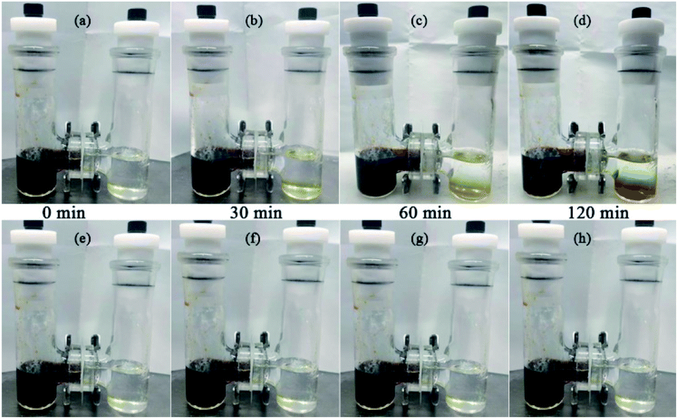 | ||
| Fig. 5 Simulation of polysulfides diffusion with PP (a)–(d) and the PP–Ox−–U (e)–(h). | ||
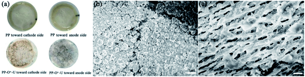 | ||
| Fig. 6 (a) Digital photos of PP (top) and the PP–Ox−–U (bottom) after cycling, SEM images of (b) PP, (c) PP–Ox−–U toward cathode side after cycling. | ||
In order to understand the stability of separators and investigate the electrode kinetics process, electrochemical impedance spectroscopies (EIS) of all samples before and after 500 cycles were shown in Fig. 7a and b, respectively. Rs, Rct and Ri represent total internal resistance (the resistance of electrolyte, electrode, and separator), charge transfer resistance and the interface resistance of the SEI layer, respectively. As shown in Fig. 7a, the battery with PP–Ox−–U demonstrates the smallest resistance values of Rs (4.5 Ω) and Rct (31.4 Ω) among all samples. The detailed impedance parameters simulated by the equivalent circuit model are summarized in Table S1.† The battery with PP shows two bigger semicircles after cycling, which mean greater charge transfer resistance (Rct) at the cathode and interface resistance (Ri).23 The second semicircle appears in the medium frequency region, obviously, which is due to the conversion of partial polysulfides into solid lithium sulfide on the separator surface, leading to a larger interface resistance (Ri) (the previous SEM confirms this in Fig. 6b).38 It is noteworthy that the smaller semicircles in the battery with the PP–Ox−–U are displayed (insert in Fig. 7b), which may be that the wettability improvement of PP–Ox−–U promotes the conductivity of ions, indicating that the interface resistance between grafted organosiloxane layer and cathode is smaller (the previous contact angle can confirm this). As for the battery with PP–Ox−, the only one semicircle indicates that the interface is not formed, which may be due to the lack of chemical anchoring of organosiloxane and the immigration of polysulfides onto the anode side. Therefore, it is believed that the PP–Ox−–U separator can not only suppress the polysulfides shuttling but also reduce the interface resistance. The charge–discharge profiles were illustrated in Fig. 7c. When the batteries are discharged at 1C, all discharge profiles exhibit two plateaus at 2.3–2.4 and 2.1 V, which correspond to the reduction of S8 to long-chain polysulfide Li2Sx (x = 4, 6 and 8) and the further reduction to Li2S2 and Li2S, respectively. It can be seen that the battery with PP–Ox−–U demonstrates the longest voltage plateau and the lowest voltage hysteresis (ΔE) among all the charge–discharge curves. The type of sulfur species loss during cycling is further analyzed by using the capacity contribution of the upper discharge plateau (QH) and the lower discharge plateau (QL). The theoretical value of QH (419 mA h g−1) reflects the transformation of solid sulfur into high-order soluble polysulfides, and QL (837.5 and 1256 mA h g−1) reflects the conversion of high-order polysulfides into insoluble polysulfides (Li2S2/Li2S).39,40 Theoretical calculation results show that QL/QH = 3 is completely converted to Li2S, while the conversion to Li2S2 leads to QL/QH = 2.41 The ratio of QL to QH determines the effective utilization of the redox species.39 The batteries with PP and PP–Ox− in Fig. 7c show 26.7% (111.8 mA h g−1) and 51.3% (214.8 mA h g−1) of the theoretical QH at 1C, respectively, while lower QL was observed (20.7% and of 44.1% of theoretical QL at 1C, respectively). At the same current density, the battery with PP–Ox−–U displays 55.7% and 49.7% of the theoretical QH and QL, respectively. Besides, the battery with PP–Ox−–U also possesses the largest QL/QH value of 2.68, while the other two samples are 2.32 and 2.58 (Table 1). These results show that the battery with PP–Ox−–U has the lowest polarization and highest utilization of the redox species compared to the additional two samples, which are mainly attributed to the fact that improvement of wettability facilitates ion's diffusion and the grafted functional groups can effectively block the transport of the dissolved polysulfides.
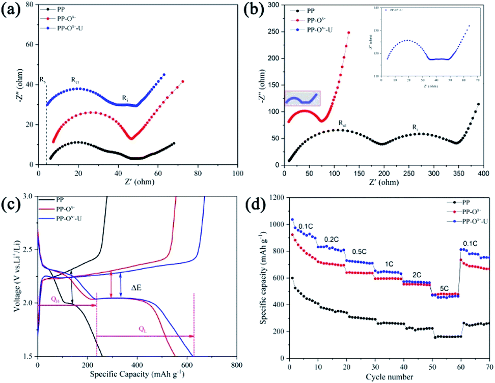 | ||
| Fig. 7 (a and b) EIS plots before and after 500 cycles, (c) the charge–discharge curves at 1C, and (d) rate performance. | ||
| Samples | QH | QL | QH practical/QH theoretical | QL practical/QL theoretical | QL/QH |
|---|---|---|---|---|---|
| PP | 111.8 | 259.9 | 26.70% | 20.70% | 2.32 |
| PP–Ox− | 214.8 | 553.6 | 51.30% | 44.10% | 2.58 |
| PP–Ox−–U | 233.4 | 624.6 | 55.70% | 49.70% | 2.68 |
In consideration of the above analysis, outstanding rate performance is also expected. As shown in Fig. 7d, the initial discharge capacity of the battery with PP is 600 mA h g−1 at 0.1C but only delivers 163 mA h g−1 at 5C. When the rate is restored to 0.1C, a reversible discharge capacity of 264 mA h g−1 was restored, which is 44.0% of the initial discharge capacity. Comparatively, the battery with PP–Ox−–U indicates a higher discharge capacity of 1037 mA h g−1 at 0.1C, and it still delivers a high capacity of 470 mA h g−1 even at 5C. Particularly, when the discharge rate is switched abruptly from 5C to 0.1C, a high reversible discharge capacity of 815 mA h g−1 was retrieved, which is 78.6% of the initial discharge capacity. This is because the PP–Ox−–U separator substantially suppresses the shuttle effect of polysulfides during the cycling process. It is worth mentioning that the rate performance of battery with PP–Ox−–U is better than that with PP–Ox− except that the PP–Ox− is slightly superior to the PP–Ox−–U at 5C. This may be because, at high current density, polysulfide ions exist for a very short time. Due to the difference in wettability (the previous contact angle confirms it), the conversion reaction between S8 and Li2S of battery with PP–Ox− is faster than that with PP–Ox−–U during the charge–discharge process.
The excellent rate performance and high specific capacity of Li–S battery with the PP–Ox−–U separator can be attributed to the fact that the grafting of organosiloxane containing amine and silanol group can effectively inhibit the shuttled polysulfides during cycling, and the improvement of wettability can promote the ionic conductivity. The unique single-sided enlarged channel structure formed by chemical tailoring can well accommodate the deposition with intermediate polysulfides on the separator surface toward cathode chamber. And the high reutilization of active materials also implies that the battery with PP–Ox−–U has achieved good effects in blocking the polysulfides diffusion. Table 2 summarizes the enhanced electrochemical performance of the lithium–sulfur battery by organosiloxane modified membrane and other modified membrane reported in the literature. The experimental results demonstrate that the Li–S battery with PP–Ox−–U in this work has competitive electrochemical performance including high capacity stability, rate performance and excellent long–term cycle stability.
| Cathodes | Initial capacity | Final capacity [mA h g−1] | Fading rate (%) | Separators | Rate | References |
|---|---|---|---|---|---|---|
| GO/S | 786 mA h g−1 | 580 after 250 cycles | 0.11% | PP–g–PAA2 | 0.2C | 23 |
| KB/S | 1204 mA h g−1 | 802 after 100 cycles | 0.33% | P-carbon-coated P-separator | 0.2C | 25 |
| KB/S | 1070 mA h g−1 | 689 after 100 cycles | 0.35% | KB@Ir-30 | 0.2C | 42 |
| KB/S | 1037 mA h g−1 | 510 after 500 cycles | 0.10% | PP–Ox−–U | 0.5C | This work |
Conclusions
A special functionalization separator for lithium–sulfur battery is prepared through PP single-sided chemical tailoring, and organosiloxane fumigation grafting. The grafted functional molecule containing rich active groups such as amine or/and silicon hydroxyl can not only build a strong interaction with polysulfides by chemical anchoring, but also improve the hydrophilicity of separator in a polar solvent, effectively improving the long cyclic stability and facilitating the transportation of lithium-ions. At the same time, the functionalization separator (PP–Ox−–U) with one side enlarged pore structure formed by chemical tailoring can also be used as a “polysulfide storage tank”. It can well accommodate the intermediate polysulfides deposited on the surface of the separator toward the cathode chamber, achieving the high initial capacity and excellent rate performance. Therefore, although the routine carbon black and S are used as the cathode, at 0.5C and 2C, the lithium–sulfur batteries with PP–Ox−–U present high initial capacity of 1037 mA h g−1 with a low capacity fading of 0.10% per cycle and 786 mA h g−1 with a low capacity fading of 0.095% per cycle after 500 cycles, respectively. Unlike the previous approach to block the polysulfides by the additional coating or interlayer, the strategy by the separator itself functionalization does not affect energy density of the battery system, which is of great significance for the future application of Li–S batteries.Conflicts of interest
The authors declare no conflict of interest.Acknowledgements
The authors gratefully acknowledge the financial support from the National Natural Science Foundation of China (51572078, 51772086, 51872087 and 51971089), the Natural Science Foundation of Hunan Province (No. 2018JJ2038) and the Major Science and Technology Program of Changsha (kq1804010).References
- P. G. Bruce, S. A. Freunberger, L. J. Hardwick and J. M. Tarascon, Nat. Mater., 2012, 11, 19–29 CrossRef CAS PubMed.
- R. Van Noorden, Nature, 2014, 507, 26–28 CrossRef CAS PubMed.
- T. Li, C. He and W. Zhang, J. Mater. Chem. A, 2019, 7, 4134–4144 RSC.
- G. Jiang, F. Xu, S. Yang, J. Wu, B. Wei and H. Wang, J. Power Sources, 2018, 395, 77–84 CrossRef CAS.
- J. Cheng, D. Zhao, L. Fan, X. Wu, M. Wang, N. Zhang and K. Sun, J. Mater. Chem. A, 2017, 5, 14519–14524 RSC.
- J. Cao, C. Chen, Q. Zhao, N. Zhang, Q. Lu, X. Wang, Z. Niu and J. Chen, Adv. Mater., 2016, 28, 9629–9636 CrossRef CAS PubMed.
- G. Yuan, G. Wang, H. Wang and J. Bai, J. Solid State Electrochem., 2015, 19, 1143–1149 CrossRef CAS.
- A. Manthiram, Y. Fu, S. H. Chung, C. Zu and Y. S. Su, Chem. Rev., 2014, 114, 11751–11787 CrossRef CAS PubMed.
- N. Díez, G. A. Ferrero, M. Sevilla and A. B. Fuertes, Sustainable Energy Fuels, 2019, 3, 3498–3509 RSC.
- J. Q. Huang, H. J. Peng, X. Y. Liu, J. Q. Nie, X. B. Cheng, Q. Zhang and F. Wei, J. Mater. Chem. A, 2014, 2, 10869–10875 RSC.
- S. Liu, Z. Wang, C. Yu, H. B. Wu, G. Wang, Q. Dong, J. Qiu, A. Eychmüller and X. W. Lou, Adv. Mater., 2013, 25, 3462–3467 CrossRef CAS PubMed.
- W. Zhou, Y. Yu, H. Chen, F. J. DiSalvo and H. D. Abruna, J. Am. Chem. Soc., 2013, 135, 16736–16743 CrossRef CAS PubMed.
- J. Xiang, Z. Guo, Z. Yi, Y. Zhang, L. Yuan, Z. Cheng, Y. Shen and Y. Huang, J. Energy Chem., 2020, 49, 161–165 CrossRef.
- J. Han, Y. Li, S. Li, P. Long, C. Cao, Y. Cao, W. Wang, Y. Feng and W. Feng, Sustainable Energy Fuels, 2018, 2, 2187–2196 RSC.
- D. Liu, Q. Li, J. Hou and H. Zhao, Sustainable Energy Fuels, 2018, 2, 2197–2205 RSC.
- A. Bhargav, S. V. Patil and Y. Fu, Sustainable Energy Fuels, 2017, 1, 1007–1012 RSC.
- J. Wutthiprom, N. Phattharasupakun, J. Khuntilo, T. Maihom, J. Limtrakul and M. Sawangphruk, Sustainable Energy Fuels, 2017, 1, 1759–1765 RSC.
- C.-H. Chang, S.-H. Chung and A. Manthiram, Sustainable Energy Fuels, 2017, 1, 444–449 RSC.
- D. An, L. Shen, D. Lei, L. Wang, H. Ye, B. Li, F. Kang and Y.-B. He, J. Energy Chem., 2019, 31, 19–26 CrossRef.
- J. Song, C. Zhang, X. Guo, J. Zhang, L. Luo, H. Liu, F. Wang and G. Wang, J. Mater. Chem. A, 2018, 6, 16610–16616 RSC.
- N. Kaisar, S. A. Abbas, J. Ding, H. A. Chen, C. W. Pao, K. M. Boopathi, A. Mohapatra, Y. T. Chen, S. H. Wu, J. Fang, S. Jou and C. W. Chu, Nanoscale, 2019, 11, 2892–2900 RSC.
- H. Shao, F. Ai, W. Wang, H. Zhang, A. Wang, W. Feng and Y. Huang, J. Mater. Chem. A, 2017, 5, 19892–19900 RSC.
- S. Song, L. Shi, S. Lu, Y. Pang, Y. Wang, M. Zhu, D. Ding and S. Ding, J. Membr. Sci., 2018, 563, 277–283 CrossRef CAS.
- Q. Dong, R. Shen, C. Li, R. Gan, X. Ma, J. Wang, J. Li and Z. Wei, Small, 2018, 14, e1804277 CrossRef PubMed.
- J. H. Ahn, H.-J. Shin, S. Abbas, K.-Y. Lee and H. Y. Ha, J. Mater. Chem. A, 2019, 7, 3772–3782 RSC.
- R. Morent, N. De Geyter, C. Leys, L. Gengembre and E. Payen, Surf. Interface Anal., 2008, 40, 597–600 CrossRef CAS.
- J. K. Premachandra, W. J. Van Ooij and J. E. Mark, J. Adhes. Sci. Technol., 1998, 12, 1361–1376 CrossRef CAS.
- C. R. Ryder, J. D. Wood, S. A. Wells, Y. Yang, D. Jariwala, T. J. Marks, G. C. Schatz and M. C. Hersam, Nat. Chem., 2016, 8, 597–602 CrossRef CAS PubMed.
- Y. Li, Y. Zhao, H. Cheng, Y. Hu, G. Shi, L. Dai and L. Qu, J. Am. Chem. Soc., 2012, 134, 15–18 CrossRef CAS PubMed.
- J. Wu, S. Ding, S. Ye and C. Lai, J. Energy Chem., 2020, 42, 27–33 CrossRef.
- P. Burg, P. Fydrych, D. Cagniant, G. Nanse and A. Jankowska, Carbon, 2002, 40, 1521–1531 CrossRef CAS.
- Y. He, Y. Qiao, Z. Chang, X. Cao, M. Jia, P. He and H. Zhou, Angew. Chem., Int. Ed., 2019, 58, 11774–11778 CrossRef CAS PubMed.
- L. Yin, G. Xu, P. Nie, H. Dou and X. Zhang, Chem. Eng. J., 2018, 352, 695–703 CrossRef CAS.
- W. Zhang, S. Wang, J. Ji, Y. Li, G. Zhang, F. Zhang and X. Fan, Nanoscale, 2013, 5, 6030–6033 RSC.
- X. Yu, Z. Wang, Z. Wei, S. Yuan, J. Zhao, J. Wang and S. Wang, J. Membr. Sci., 2010, 362, 265–278 CrossRef CAS.
- W. Xue, Q.-B. Yan, G. Xu, L. Suo, Y. Chen, C. Wang, C.-A. Wang and J. Li, Nano Energy, 2017, 38, 12–18 CrossRef CAS.
- J. Li, Y. Huang, S. Zhang, W. Jia, X. Wang, Y. Guo, D. Jia and L. Wang, ACS Appl. Mater. Interfaces, 2017, 9, 7499–7504 CrossRef CAS PubMed.
- J. Sun, Y. Sun, M. Pasta, G. Zhou, Y. Li, W. Liu, F. Xiong and Y. Cui, Adv. Mater., 2016, 28, 9797–9803 CrossRef CAS PubMed.
- J. Zhou, R. Li, X. Fan, Y. Chen, R. Han, W. Li, J. Zheng, B. Wang and X. Li, Energy Environ. Sci., 2014, 7(8), 2715–2724 RSC.
- L. Qie, C. Zu and A. Manthiram, Adv. Energy Mater., 2016, 6(7), 1502459 CrossRef.
- D. Ghosh, M. Gad, I. Lau and M. A. Pope, Adv. Energy Mater., 2018, 8, 1801979 CrossRef.
- P. Zuo, J. Hua, M. He, H. Zhang, Z. Qian, Y. Ma, C. Du, X. Cheng, Y. Gao and G. Yin, J. Mater. Chem. A, 2017, 5, 10936–10945 RSC.
Footnote |
| † Electronic supplementary information (ESI) available. See DOI: 10.1039/d0ra02833a |
| This journal is © The Royal Society of Chemistry 2020 |