 Open Access Article
Improvement of mechanical properties of in situ-prepared HTPE binder in propellants
Keke Chena,
Xiaomu Wena,
Guoping Li*ab,
Siping Pang ab and
Yunjun Luo
 *ab
*ab
aSchool of Materials Science and Engineering, Beijing Institute of Technology, Beijing, 100081, China. E-mail: girlping3114@bit.edu.cn; yjluo@bit.edu.cn
bKey Laboratory for Ministry of Education of High Energy Density Materials, Beijing, 100081, China
First published on 17th August 2020
Abstract
A new type of hydroxyl-terminal block copolymer (HTPE) binder with excellent mechanical properties was prepared using an in situ preparation method. Compared with traditional HTPE binder preparation, this method involves relatively simple operations, which not only reduces costs, but also does not require a complicated synthesis process to prepare the HTPE prepolymer intermediate. Thus, it is expected to replace the binder for HTPE propellants. The mechanical properties, crosslinking density, hydrogen bonding, and thermal performances of the prepared HTPE binders were investigated through tensile testing, low-field nuclear magnetic resonance (LF-NMR), Fourier-transform infrared spectroscopy (FTIR), and differential scanning calorimetry (DSC) analysis. The ultimate tensile strength (σm) of the in situ-prepared HTPE binder was 1.83 MPa, the fracture elongation (εb) was 371.61%, and the strength increased by 80% compared to the HTPE binders. The crosslink density (Ve) decreased with an increasing content of PEG and/or TDI. The proportion of H-bonds formed by the imino groups increased with the content of PEG and TDI and reached 81.49% at PEG and TDI contents of 50% and 80%, respectively, indicating a positive correlation between the H-bonds and σm. Based on the statistical theory of elasticity, the integrity of the curing networks showed that the contents of PEG and TDI affected the integrity of the curing networks. The DSC data of the in situ-prepared HTPE binder showed a lower glass transition temperature. Finally, compared to HTPE propellant, the strength and elongation of the in situ-prepared HTPE propellant increased by 206% and 135%, respectively. This exciting result greatly enhances the feasibility of the in situ HTPE preparation method.
1. Introduction
Hydroxyl-terminal block copolymer (HTPE) was developed in the 1990s as an insensitive replacement of hydroxyl-terminated polybutadiene-based composite solid propellants. It has a less severe response in low vulnerability testing.1–7 The HTPE prepolymer binder is typically synthesized by the active open-loop polymerization of polyethylene glycol (PEG) and polytetramethylene-ether-glycol (PTMG).8,9 It is difficult to control the block structure in this complex synthesis route with a low yield. Therefore, novel polymerization methods have drawn much attention. Holmqvist10,11 reported a polyethylene oxide–polytetrahydrofuran–polyethylene oxide (PEO–PTHF–PEO) triblock copolymer and compared it with polyethylene oxide/polypropylene oxide. Gerfried12 used an acid catalyst to obtain polytetrahydrofuran and PEG block copolymer at high temperatures under an inert atmosphere. The molecular weight dispersion coefficient was 1.5–2.0. Neumer13 produced a segmented copolymer of PTMEG and formaldehyde by an acidic-catalyzed condensation reaction of PTMEG and formaldehyde in a cyclohexylamine solution. However, this required extensive purification, including catalyst extraction and solvent drive-off. Luo14 designed a new method to prepare a new kind of PTHF–PEO–PTHF HTPE. Macromolecular polyethylene glycol was the initiator in this method, and the boroethertrifluoride complex was the catalyst. Cationic open-loop polymerization of tetrahydrofuran occurred with a trace amount of epoxy propane, and the polytetrahydrofuran ether chain was bonded directly on both sides of the PEG. However, the uncertain molecular structure resulted in a molecular chain due to the epoxy propane. Hevus15 used a commercial hydroxyl-terminated polytetrahydrofuran and polyethylene glycol producing polytetrahydrofuran/polyethylene glycol copolymer with multiple segments through coupled reactions of toluene diisocynate (TDI) and hydroxyl groups.This work is dedicated to preparing a new type of hydroxyl-terminated block copolymer (HTPE) binder with excellent mechanical properties through an in situ preparation method. As the traditional HTPE propellant binder is composed of polytetrahydrofuran and polyethylene glycol multi-blocks, the low viscosity of PEG and PTMG with low molecular weights contributed to the mixing and pouring process of the composite solid propellants. In addition, due to the lack of soft segments, the strength of the HTPE propellant is insufficient, especially under high-temperature conditions. Due to the large difference in the reactivities of the NCO groups in TDI and (polyfunctional isocyanate) N100, it is possible to achieve a more reactive TDI to preferentially react with the –OH groups in the PEG/PTMG to achieve the effect of chain extension and ensure that the binders synthesized by this method have enough molecules to achieve good mechanical properties. Therefore, the binder made by this innovative in situ preparation method has more urethane groups, which could improve the strength of both the binder and propellant. Compared with the traditional HTPE binder preparation, this method involves a relatively simple operation process, which not only lowers costs but also does not require a complicated synthesis process to prepare the HTPE prepolymer intermediate. Thus, it is expected to replace the binder for HTPE propellants. The in situ-prepared HTPE binder was directly prepared by an in situ reaction of TDI and N100 in different proportions with PEG and PTMG.
Herein, low-molecular-weight PEG and PTMG were used as the mixed segments. TDI and N100 polyisocyanate were used as the chain extender and crosslinker to obtain a HTPE based polyurethane (PU). Soft and hard segment block structures were precisely controlled during polymerization, and the mechanical strength, thermal decomposition, and other properties of the prepared binders were systemically studied to analyze the correlation with the block structure. This reaction occurred under normal temperature and pressure and a neutral chemical environment without the addition of solvent. Moreover, HTPE-based propellants prepared with this innovative method have not yet been reported.
The excellent mechanical properties of the in situ-prepared HTPE binder will be the basis of new architectures, and these polymers have potential uses in propellant applications.
2. Experimental
2.1 Materials
The details of the chemical reagents in this work and their parameters are as follows. PEG with an average relative molecular mass Mn ≈ 200 and average functionality of 2 was obtained from Xi Long Chemical Co., Ltd. PTMG was obtained from the Shanxi Province Chemical Research Institute with a number average molecular weight Mn ≈ 1000 and average functionality of 2. HTPE14 was self-prepared in our university lab with an average relative molecular mass Mn ≈ 4600 and hydroxyl value of 32.26 mg KOH per g. High-purity (>99.5 vol%) toluene diisocyanate (TDI-80/20) with 2,4-TDI and 2,6-TDI contents of 80% and 20%, respectively, was obtained from Tianjin Guangfu Fine Chemical Research Institute. Polyfunctional isocyanate (N100) with a number-average molecular weight Mn = 725 and average functionality of 3.87 was obtained from the Liming Research Institute of Chemical Industry (Henan, China). Triphenyl bismuth (TPB) (purity of 99%) was obtained from Shanghai Institute of Organic Chemistry (Shanghai Municipality, China) and was formulated into a 0.5 wt% solution with dioctyl sebacate (DOS) as the solvent. Dibutyltin dilaurate (T12) from Shanghai Institute of Organic Chemistry (Shanghai Municipality, China) was formulated into a 0.5 wt% solution with dioctyl sebacate (DOS) as the solvent. Dioctyl sebacate (DOS) was analytically pure and obtained from Tianjin Guangfu Fine Chemical Research Institute. Bonding agent LBA-278, terminal cyano, and hydroxy-substituted polyamine was provided by Luoyang Liming Chemical Research Institute. Aluminum powder (Al), supplied by Jintian Aluminum Co., Ltd., had an average particle size of 6.8 μm. Fine grain ammonium perchlorate (AP), supplied by the Dalian Potassium Chlorate Plant, had an average particle size of 102 μm. Coarse grain ammonium perchlorate (AP), supplied by Dalian Potassium Chlorate Plant, had an average particle size of 300 μm,. Cyclotrimethylenetrinitramine (RDX), supplied by Jintian Aluminum Co., had an average particle size of 88 μm.The PEG, PTMG, and HTPE binders mentioned above were vacuum dried at 60 °C for 9 h. Aluminum powder (Al), ammonium perchlorate (AP), and cyclotrimethylenetrinitramine (RDX) were dried in an oven at 60 °C for 7 d.
2.2 Preparation process
The main procedures for the preparation of the in situ-prepared HTPE binder are described as follows. Prepolymer PEG and PTMG1000 were first blended uniformly in a certain stoichiometric ratio followed by the addition of the curing agents TDI and N100 successively with 10 min of stirring for each. Finally, 0.3 wt% of the curing catalyst (the mass ratio of the TPB solution to the T12 solution was 3![[thin space (1/6-em)]](https://www.rsc.org/images/entities/char_2009.gif) :
:![[thin space (1/6-em)]](https://www.rsc.org/images/entities/char_2009.gif) 1) was added with 10 min of stirring to achieve uniform mixing. The final mixture was further stirred and vacuumed at a temperature of 40 °C for 1 h to remove the air bubbles. It was then poured into a polytetrafluoroethylene matrix for casting into binder-shaped samples.
1) was added with 10 min of stirring to achieve uniform mixing. The final mixture was further stirred and vacuumed at a temperature of 40 °C for 1 h to remove the air bubbles. It was then poured into a polytetrafluoroethylene matrix for casting into binder-shaped samples.
The main procedures for the preparation of the HTPE binder are described as follows. Prepolymer HTPE was first blended uniformly at a stoichiometric ratio followed by the addition of the crosslinker agent N100 with 10 min of stirring for each. Finally, 0.3 wt% of the curing catalyst (the mass ratio of the TPB solution to the T12 solution was 3![[thin space (1/6-em)]](https://www.rsc.org/images/entities/char_2009.gif) :
:![[thin space (1/6-em)]](https://www.rsc.org/images/entities/char_2009.gif) 1) was added with 10 min of stirring to achieve uniform mixing. The final mixture was further stirred and vacuumed at a temperature of 40 °C for 1 h to remove the air bubbles. It was then poured into a polytetrafluoroethylene matrix for casting into binder-shaped samples.
1) was added with 10 min of stirring to achieve uniform mixing. The final mixture was further stirred and vacuumed at a temperature of 40 °C for 1 h to remove the air bubbles. It was then poured into a polytetrafluoroethylene matrix for casting into binder-shaped samples.
The binders described above were placed in a desiccator for 24 h after curing in the incubator at 60 °C for 7 d. The sample preparation processes needed to be performed under ambient conditions with humidity values lower than 30% and a temperature around 25 °C. Moreover, the processing conditions, such as the stirring time, also must be well controlled. An HTPE binder was prepared using a procedure similar to that described above.
The PEG/PTMG and TDI/N100 ratios are important design parameters for obtaining chemical crosslinking in the in situ-prepared HTPE binders. In the prepared binder samples, the molar contents of PEG (χ) were varied in the range of 20–80%, and the molar content of TDI (γ) was varied in the range of 20–80%. The χ and γ values of the binder samples that were selected as curing parameters in this study are listed in Table 1.
| In situ-prepared HTPE binders with different χ | In situ-prepared HTPE binders with different γ | HTPE propellants | ||||
|---|---|---|---|---|---|---|
| Symbol | χ | Symbol | γ | Ingredients/composition | In situ-prepared HTPE propellant | HTPE propellant |
| a χ represents the ratio of –OH in the PEG to the total –OH in the PEG and PTMG; γ represents the ratio of –NCO in the TDI to the total NCO in the TDI and N100. | ||||||
| Sp20 | 20% | ST20 | 20% | AL | 18% | 18% |
| SP30 | 30% | ST30 | 30% | Fine grain AP | 32% | 32% |
| SP40 | 40% | ST40 | 40% | Coarse grain AP | 20% | 20% |
| SP50 | 50% | ST50 | 50% | RDX | 10% | 10% |
| SP60 | 60% | ST60 | 60% | Bu-NENA | 10% | 10% |
| SP70 | 70% | ST70 | 70% | Binder | 9.5% | 9.5% |
| ST80 | 80% | Bonding agent | 0.2% | 0.2% | ||
| Catalyst | 0.3% | 0.3% | ||||
The sample preparation processes needed to be performed under ambient conditions with a humidity of less than 30% and a temperature of approximately 25 °C. Moreover, the processing conditions, such as the stirring time, also needed to be well controlled. Using a process similar to that described above, an HTPE binder was also prepared for comparison, denoted as SH, whose R value (the curing parameter R denotes the equivalent ratio of isocyanate (–NCO) to hydroxyl (–OH) groups, R = 1.2) was consistent with the in situ-prepared HTPE binders. γ represents the ratio of –NCO in the TDI to the total NCO in the TDI and N100.
PEG/PTMG and other liquid ingredients (except curative) were charged into a kneading mixer with a capacity of 5 L and mixed for 30 min. Next, aluminum powder was added in two steps. Ammonium perchlorate powder and RDX were added separately so that homogenous mixing could occur. The overall mixing temperature was maintained at 50 °C. After the addition of all of the solid ingredients, the mixing was performed under a vacuum environment at 50 °C and −0.1 MPa and kneaded for 1.5 h at a kneading speed of 50 rpm. At this stage, TDI and N100 were added, and the mixture was further mixed for another 30 min followed by vacuum mixing for another 30 min to drive out entrapped air. Finally, a curing catalyst was added, and the mixture was kneaded for 1.5 h at a kneading speed of 50 rpm in a vacuum environment at 50–60 °C and −0.1 MPa. The mixture was cast into a mold and cured at 50 °C for 7 d, and the cured sample was used to evaluate its different properties. Using a process similar to that described above, a HTPE propellant was also prepared for comparison, whose R value (R = 1.2) was consistent with the in situ-prepared HTPE propellant, but the binder was different.
The propellant samples contained 80% solid filler, 9.5% binder, 10% plasticizer, and 0.5% other materials. In addition, the binder for the in situ-prepared HTPE propellant was ST80, and the binder for the HTPE propellant was SH. The specific formulations of the in situ-prepared and HTPE propellants are given in Table 1.
2.3 Measurements
A WD-4005 AGS-J electronic universal testing machine (Shimadzu Corporation, GB/T 528-1998) was used to perform tensile tests using dumbbell-shaped samples at 25 °C with a strain rate of 100 mm min−1. The crosslink density was examined with a VTMR20010V-T low-field NMR spectrometer provided by the Shanghai Newman Corporation. Fourier-transform infrared spectroscopy (FTIR) measurements were performed using a Nicolet 8700 from the Thermo Electron Corporation. These were performed with 48 scans in the middle infrared region with a spectral resolution of 2 cm−1 and spectral range 4000–500 cm−1. Binder samples with masses of 10 mg were placed in alumina pans and subjected to differential scanning calorimetry (DSC) analysis in a Setaram DSC131 under a nitrogen atmosphere at a flow rate of 40 mL min−1 with a heating temperature range of −100 to 150 °C.3. Results and discussion
3.1 Infrared spectrum
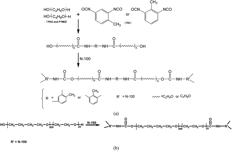
The binder plays a critical role in forming a three-dimensional network through chemical reactions. It provides combustible elements, such as carbon and hydrogen, in the combustion process and bonds with various filler components in the propellant to produce good mechanical properties. The binder generally must meet the following basic conditions: (1) the binder must be a liquid low-volatile prepolymer capable of withstanding the high vacuum during the mixing and casting of the slurry. (2) The binder must have good compatibility with other components in the propellant. (3) The binder must have a higher volume fraction of the solid filler, i.e., a lower viscosity. (4) The binder must have good curing reaction capabilities, i.e., the curing reaction can be carried out at a lower temperature (less than 60–70 °C), and the small molecule product must not be released in the reaction. The crosslinking reaction should be controllable such that the slurry has adequate fluidity during the mixing and casting and to ensure that the slurry has a sufficient pot life. (5) The binder must have a lower glass transition temperature.The prepolymers PEG and PTMG used were low-volatility liquid polymers with low viscosities, low glass transition temperatures, and good curing reaction properties. These features satisfied the requirements of solid propellants for binders. In this experiment, PEG and PTMG were used as the mixed soft segment, and the chains were extended by the reaction of –NCO groups in TDI with –OH in the polyether soft segment so that PEG and PTMG were connected by TDI hard segments. The system formed a crosslinked network structure via N100 to combine the excellent properties of the two systems. The specific reaction principles are shown in Fig. 1a. The curing reaction for synthesizing the HTPE binder is shown in Fig. 1b.
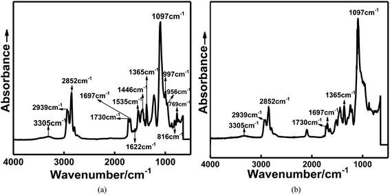
To confirm that the in situ-prepared HTPE binder had formed, the structure of the prepared binder was characterized by FTIR, as shown in Fig. 2.
Fig. 2 shows the infrared spectra of the in situ-prepared HTPE and HTPE binders. The wide absorption band at 3305 cm−1 is caused by valence vibrations of the associated amide NH groups. An amide band is found at 1535 cm−1. A doublet of the absorption bands at 1097 cm−1 appeared, indicating that the product molecular chain contained ether bonds (C–O–C), and methylene appeared at 2852 and 2939 cm−1. The stretching vibration of amine (–NH) bond on urethane linkages appeared at 3345 cm−1, and the stretching vibration of amide carbonyl (–C![[double bond, length as m-dash]](https://www.rsc.org/images/entities/char_e001.gif) O) bond appeared at 1730 cm−1 and 1697 cm−1, indicating the formation of new urethane groups. In addition, the presence of 2,4-tolylene and 2,6-tolylene moieties is confirmed by absorption bands at 769, 816, 956, and 997 cm−1 (out-of-plane and in-plane deformation vibrations of aromatic C–H bonds, respectively), 1353 cm−1 (symmetric stretching of methyl group in tolylene fragment), and 1446 and 1622 cm−1 (vibrations of the aromatic ring). These analyses show that the HTPE-based polyurethane binders were successfully synthesized. The structures of the synthesized polymers are confirmed by FTIR.
O) bond appeared at 1730 cm−1 and 1697 cm−1, indicating the formation of new urethane groups. In addition, the presence of 2,4-tolylene and 2,6-tolylene moieties is confirmed by absorption bands at 769, 816, 956, and 997 cm−1 (out-of-plane and in-plane deformation vibrations of aromatic C–H bonds, respectively), 1353 cm−1 (symmetric stretching of methyl group in tolylene fragment), and 1446 and 1622 cm−1 (vibrations of the aromatic ring). These analyses show that the HTPE-based polyurethane binders were successfully synthesized. The structures of the synthesized polymers are confirmed by FTIR.
In addition to the absence of the benzene ring structure, the main difference compared to the in situ-prepared HTPE binders were that the 2200 cm−1 peak attributed to the isocyanate absorption appears in the infrared absorption spectrum of the HTPE binders. The main reason for this difference is that the molecular weight of the HTPE prepolymer (4000) is larger than that of the in situ-prepared HTPE binder (200–400), making the synthesis reactivity of the HTPE binders are lower than that of the in situ-prepared HTPE binders, so there exists residual curing agent in the HTPE binder.
3.2 Mechanical properties
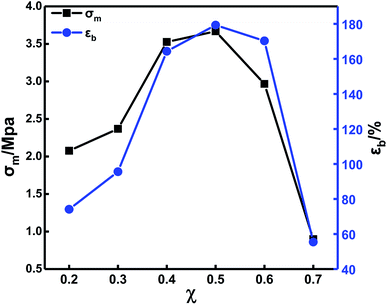
The mechanical properties of the solid propellants are determined by the binder. The curing parameters play an important role in the mechanical properties of the binder. Both PEG and PTMG are hydroxyl (–OH)-terminated polyether, which can react with isocyanate (–NCO) to form carbamates. The difference is that the PEG has a smaller molecular weight and higher reactivity. The blending of these two has a greater impact on the mechanical properties and the crosslinking network structure. Therefore, it is important to study the blending ratio of PEG/PTMG and examine its effect on the mechanical properties of the binder. First, the binder file mechanical properties were investigated by changing the PEG/PTMG ratio with TDI/N100 = 1 and R = 1.2 (the value of R was used in all the subsequent analysis.).Fig. 3 shows that the ultimate tensile strength (σm) and the fracture elongation (εb) increase with increasing PEG content. They reach maxima at a PEG content of 50%. Decreases in both σm and εb were detected with further increases in the PEG content. Compared to the PTMG, the PEG binder exhibits a small steric hindrance and a higher molecular chain activity because the PEG has a small molecular weight—this causes a higher reaction activity. Therefore, TDI preferentially extended the chain reaction with PEG in the blending system.
There are more hard segments of polyurethane elastomers with a fixed R value and a high hydroxyl value due to the PEG content and greater amount of curing agent. Thus, σm increases with increasing PEG content. The content of oxygen atoms in the segments of PEG is higher than that in the PTMG, and the flexibility of the chains is better. Therefore, εb increases as the content of PEG increases. When the content of PEG continues to increase, the content of PTMG decreases accordingly leading to defects in the crosslinked network structure and a reduction in σm and εb.
TDI is a difunctional curing agent and acts as a chain extender for PEG and PTMG. When N100 is the only polyfunctional component in the formulation, it functions as a crosslinking agent in the crosslinked network. Therefore, the change of the TDI/N100 ratio inevitably impact the crosslinking network structure in the propellant, affecting the mechanical properties.
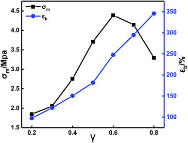
Fig. 4 shows that with increasing TDI content, σm first increases and then decreases. The εb increases continuously. In the TDI/N100 mixture, TDI has a higher activity of isocyanate groups than the N100. Thus, TDI preferentially reacts with the hydroxyl groups in PEG and PTMG to form urethane groups, leading to longer molecular chains and higher elongation. In addition, since the TDI molecule contains a benzene ring, the content of urethane groups increases with increasing TDI content. This causes micro phase separation16–18 and improvements in the mechanical properties. The further increase in the TDI content above a certain value (0.6) lead to a drastically reduced N100 content. Consequently, the density of crosslinking points and the σm of the system were reduced. By optimizing the formulation parameters of the in situ-prepared HTPE binders, a sample with good comprehensive mechanical properties (σm = 3.29 MPa, εb = 345.76%) was finally obtained.
In the present work, the corresponding values of σm and εb for the HTPE binder are 1.83 MPa and 371.61% respectively, when the curing parameter R is held constant (R = 1.2). The σm value of the in situ-prepared HTPE binder is 1.84 times that of the HTPE binders (σm = 1.78 MPa, εb = 137.79%) achieved by Mao19 and the εb is 2.52 times greater. Similar values for the HTPE binders (R = 1.2) were obtained also by Wen20 (σm = 1.6 MPa and εb = 150%). The σm of the in situ-prepared HTPE binders is significantly better than that of the HTPE binders, indicating that the in situ-prepared HTPE has potential applications in the field of solid HTPE propellants.
According to the comparative analysis, the mechanical properties of the in situ-prepared HTPE binders were superior to those of the HTPE binders. There were evident differences in the main chain structures between the two kinds of HTPE binders. The PEG and PTMG segments in the in situ-prepared HTPE binders were connected by urethane bonds formed by the hydroxyl groups of PEG and PTMG and the isocyanate in TDI, but the PEG and PTMG segments in the HTPE binders were connected by ether bonds. Because the polarity of the urethane is greater than that of the ether, the in situ-prepared HTPE binders formed hydrogen bonds more easily than the HTPE binders, and micro phase separation occurs more easily. Therefore, the mechanical properties of the in situ-prepared HTPE binders were superior to those of the HTPE binders.
3.3 Crosslink density test
For thermosetting binders and propellants, crosslinked network structures are a direct factor and have a dominant effect on the mechanical properties.21 LF-NMR is a common technique for studying the crosslinked network structure of polyurethane.22 Thus, the crosslink density of the polyurethanes in this work were examined by LF-NMR. The chemical environment and the of restraint degree of the hydrogen atoms are different in the polymer, resulting in different lateral relaxation times (T2) (i.e., the time when the transverse magnetization vector decayed to 0). In NMR, proton transitions from a higher energy level to a lower energy level occur after the RF pulse is stopped. The relaxation mechanism of hydrogen atoms is sensitive to the movement of molecular chains. Therefore, the T2 values of hydrogen atoms can be used to characterize the degree of movement and crosslinking of polymer chains. In previous work23,24 a crosslink density (XLD) analysis was done using an XLD regression model, and this model is used herein to determine the crosslink density. The expression of the XLD model is as follows:
 | (1) |
The crosslink density was obtained using the following equation after fitting each parameter using eqn (1):
 | (2) |
![[thin space (1/6-em)]](https://www.rsc.org/images/entities/char_2009.gif) 000. For 1024 points, the result is plotted in Fig. 3, which indicated that the selected parameters are reasonable.
000. For 1024 points, the result is plotted in Fig. 3, which indicated that the selected parameters are reasonable.
| Samples | T2/ms | Ve × 10−4/mol cm−3 | Mc/g mol−1 |
|---|---|---|---|
| Sp20 | 6.37 | 3.45 | 2900 |
| Sp30 | 5.33 | 3.48 | 2873 |
| Sp40 | 4.62 | 5.30 | 1890 |
| Sp50 | 3.94 | 5.85 | 1750 |
| Sp60 | 2.78 | 5.77 | 1730 |
| Sp70 | 1.61 | 6.03 | 1660 |
| ST20 | 5.09 | 5.85 | 1710 |
| ST30 | 4.92 | 5.70 | 1730 |
| ST40 | 4.06 | 5.66 | 1770 |
| ST50 | 3.94 | 5.70 | 1750 |
| ST60 | 3.62 | 5.25 | 1900 |
| ST70 | 3.50 | 5.37 | 1860 |
| ST80 | 3.89 | 5.33 | 1880 |
| SH | 3.46 | 5.07 | 1.97 |
According to Table 2, increasing the PEG content leads to an overall decrease in the T2 value of the binder. This is mainly because the increase in the PEG content in the system can increase the hard segment content, which forms more crosslinking points. More junctions will provide a stronger binding effect of the segment. Moreover, the overall T2 decreases with increasing PEG content because T2 is related to the movement ability of the molecular chain. The crosslinking density (Ve) increases continuously with increasing χ. This is because PEG has a small molecular weight but a large hydroxyl value and a large number of hydroxyl groups, which requires an increase amount of TDI/N100. However, the molecular weight between crosslinks (Mc) show the opposite variation with respect to Ve. The decrease in Mc weakens the molecular chain's ability.
Similar to PEG, the increase in γ also leads to a general decreasing trend of T2, which is related to the molecular chain's movement ability. As γ increases in the system, more TDI hard segments are mixed into the soft segment. The presence of the benzene rings in the TDI cause the segments to experience a stronger binding effect. Table 2 shows that TDI has the opposite effect on Ve to that of PEG, i.e., Ve decreases with increasing TDI. The reason for the decrease by the TDI is that the corresponding N100 polyfunctional isocyanate content decreases with increasing TDI, leading to a lower potential for the formation of crosslinking points. In situ preparation of the HTPE binder yielded a slightly higher crosslink density than that of the HTPE binder, because the molecular weights of PEG and PTMG is much smaller than that of the HTPE prepolymer.
3.4 Hydrogen bonding
The crosslinked network structure of the polyurethane binder contains not only the chemical crosslinking but also many physical crosslinks, including the entanglement of segments, hydrogen bonding between polar groups, and other interactions. Of these, hydrogen bonding can make the network structure of the polyurethane binder denser and improve the mechanical properties of the binders. For the in situ-prepared HTPE binders, H-bonds are formed either by the carbonyl (C![[double bond, length as m-dash]](https://www.rsc.org/images/entities/char_e001.gif) O) and imino (–NH–) groups on the carbamate or by the ether (–O–) and imino (–NH–) groups. Generally, the infrared absorption spectra of the carbonyl groups might be shifted toward a lower frequency upon the formation of the hydrogen bonding.25 A stronger hydrogen bonding leads to a larger shift in the absorption spectrum.
O) and imino (–NH–) groups on the carbamate or by the ether (–O–) and imino (–NH–) groups. Generally, the infrared absorption spectra of the carbonyl groups might be shifted toward a lower frequency upon the formation of the hydrogen bonding.25 A stronger hydrogen bonding leads to a larger shift in the absorption spectrum.
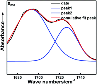
Fig. 5 shows the FTIR spectra of the carbonyl groups in the in situ-prepared HTPE binders and the HTPE binder (SH). The central wavenumber of the spectral absorption peak of the carbonyl groups is generally located in the region of 1695–1735 cm−1. Fig. 5 shows that the carbonyl absorption peak of the urethane group is clearly divided into two parts, which indicates that the spectral peak has undergone a significant frequency shift after the hydrogen bond formed. Of these, 1725 cm−1 is the absorption peak of the free carbonyl group, and 1695 cm−1 is a hydrogen-bonded carbonyl absorption peak. However, the extent to which the different absorption peaks of H-bonded and free carbonyl groups overlapped make it difficult to analyze the distinctions. These overlapping bands were resolved through multi-peak Gaussian fitting to obtain the area and peak wavenumber of each peak. The detailed solution process and final results are shown in Fig. 6 and Table 3.
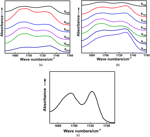 | ||
| Fig. 5 Carbonyl region of the FTIR spectra for in situ-prepared HTPE binders with different (a) χ and (b) γ and for the (c) HTPE binder. | ||
| Samples | Area (1695 cm−1) | Area (1721 cm−1) | H-bonded carbonyl (%) |
|---|---|---|---|
| Sp20 | 12.90 | 6.18 | 67.59 |
| Sp30 | 22.70 | 10.88 | 67.60 |
| Sp40 | 14.29 | 6.78 | 67.82 |
| Sp50 | 15.83 | 7.20 | 68.73 |
| Sp60 | 18.35 | 8.60 | 68.09 |
| Sp70 | 8.74 | 4.17 | 67.70 |
| ST20 | 5.70 | 2.77 | 67.30 |
| ST30 | 16.36 | 7.80 | 67.72 |
| ST40 | 17.36 | 8.07 | 68.27 |
| ST50 | 15.83 | 7.20 | 68.73 |
| ST60 | 19.43 | 8.61 | 69.29 |
| ST70 | 26.03 | 10.61 | 71.04 |
| ST80 | 38.12 | 8.66 | 81.47 |
| SH | 2.40 | 0.97 | 68.20 |
The areas of these peaks and their percentages are given in Table 3. Hydrogen bonding occurs within the in situ-prepared HTPE binders, and the central wavenumber of the carbonyl peak shifts from 1727 cm−1 to approximately 1695 cm−1, suggesting that most carbonyl groups contribute to the formation of H-bonds. Moreover, a rising trend in the percentage of H-bonded carbonyl groups occurs within the range χ = 20–50% because of the increasing concentration of carbamate (–NHCOO–) groups. The probability of bonding between the proton donating imino group (–NH–) and the carbonyl (C![[double bond, length as m-dash]](https://www.rsc.org/images/entities/char_e001.gif) O) or ether (–O–, on the PEG and PTMG backbone) groups also increases. However, when χ increases from 50% to 70%, this interaction is reduced to 69.79%. The main reason for this is that the number of short and soft segments increases, and the regular structure of the soft segments is destroyed. The compatibility of the soft and hard segments is enhanced with a further increase in the PEG content. The soft segments make the distance between some hard segments, which is not conducive to the formation of hydrogen bonds and weakens the degree of hydrogen bonding.
O) or ether (–O–, on the PEG and PTMG backbone) groups also increases. However, when χ increases from 50% to 70%, this interaction is reduced to 69.79%. The main reason for this is that the number of short and soft segments increases, and the regular structure of the soft segments is destroyed. The compatibility of the soft and hard segments is enhanced with a further increase in the PEG content. The soft segments make the distance between some hard segments, which is not conducive to the formation of hydrogen bonds and weakens the degree of hydrogen bonding.
Table 3 shows that the percentage of H-bonded carbonyl groups of the binder gradually increases with increasing γ. This is because the average molecular weights of the segments between the crosslinking points increases with increasing difunctional isocyanate content. More hard segments become embedded in the soft segments in the system, making it easier to form hydrogen bonds. The hydrogen bonding effect of the in situ-prepared HTPE binders and the HTPE binders are almost similar.
3.5 Integrity of curing networks
According to the statistical theory of the high elasticity of crosslinked structural rubber, all work done by the external forces on the system becomes the energy stored in the polyurethane binder, and the relationship between the shear modulus and the network structure parameters is as follows:| G = NkT = N′ρkT/Mc = ρRT/Mc, | (3) |
| G = (ρRT/Mc) + D. | (4) |
The correction factor A represents the comprehensive contributions to the modulus of the interactions and defects. Using eqn (4) and the existing data, the correction factors (D) of polyurethane binders with different χ and γ are calculated. The results are shown in Table 4.
| Samples | E (MPa) | Ve (10−4 mol mL−1) | Mc (g mol−1) | ρ (g cm−3) | D |
|---|---|---|---|---|---|
| Sp20 | 3.87 | 5.45 | 1840 | 1.024 | −0.4352 |
| Sp30 | 2.99 | 5.48 | 1830 | 1.024 | −0.1345 |
| Sp40 | 3.80 | 5.30 | 1890 | 1.024 | −0.0465 |
| Sp50 | 3.01 | 5.70 | 1750 | 1.024 | −0.4089 |
| Sp60 | 2.48 | 5.77 | 1730 | 1.024 | −0.6029 |
| Sp70 | 1.65 | 5.53 | 1810 | 1.024 | −0.8201 |
| ST20 | 2.29 | 5.81 | 1720 | 1.024 | −0.6761 |
| ST30 | 2.15 | 5.79 | 1730 | 1.024 | −0.7179 |
| ST40 | 2.17 | 5.66 | 1770 | 1.024 | −0.6790 |
| ST50 | 2.32 | 5.70 | 1750 | 1.024 | −0.6389 |
| ST60 | 2.39 | 5.25 | 1900 | 1.024 | −0.5041 |
| ST70 | 1.93 | 5.37 | 1860 | 1.024 | −0.6871 |
| ST80 | 1.79 | 5.33 | 1880 | 1.024 | −0.7239 |
| SH | 1.58 | 5.07 | 1970 | 1.024 | −0.7303 |
The correction factors of the in situ-prepared HTPE binders are all negative values because the measured elastic moduli are higher than those computed, which indicates that the physical crosslinked structure formed by chain entanglement and hydrogen bonding in this system is not sufficient to offset the negative effects introduced by network defects (Table 4). This is mainly because the functional distribution of curing agent N100 is relatively wide. When some isocyanate molecules with higher functionality react with the polyether to form a network structure, a cyclic structure appears, which affects the integrity of the entire crosslinked network structure. With increasing χ, the shear modulus correction factor D increases first and then decreases. It reaches a maximum value when χ is 0.5. Therefore, the most complete curing network exists in the binder with a χ value of 0.5.
Table 4 aslo shows that as the TDI content increases, the shear modulus correction factor D of the in situ-prepared HTPE binders increased continuously from −0.72 to −0.5 within the γ range 0.2–0.6, because hydrogen bonding exhibits the same trend as the content of TDI range as compensated by the network structure defects. However, excess TDI in the binder enters the crosslinking network (Ve decreases) and has negative effects on the network, even if there is a reduction in the relative content of carbamate and increased hydrogen bonding. Therefore, factor D has the opposite trend within the PEG content (γ) range of 0.6–0.8. In addition, the shear modulus correction factor D of the in situ-prepared HTPE binder is slightly higher than that of the HTPE binder, which shows that the structural integrity of the cross-linked network is better and it is more conducive to good mechanical properties. Although the correction factor remains negative, the relatively superior network which has the maximal, might be selected for application.
3.6 DSC thermal performance
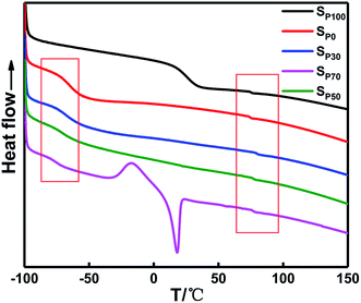
Weapons and equipment have a wide range of environmental adaptability to meet different application conditions, and the low temperature performance of solid propellants is particularly important. Relevant publications have reported that a glass transition temperature Tg < −50 °C is required for some large-scale, wall-mounted solid propellants. The low-temperature performance of propellants is mainly determined by the low-temperature performance of the binder. Therefore, the low-temperature performance of the binder is very important—especially the glass transition temperature. Therefore, in this section, the thermal performance of the in situ-prepared HTPE binder was studied and compared with that of the HTPE binder.The polyurethane structure consists of a urethane hard segment and a polyether soft segment. At room temperature, the hard segment can provide a crosslinking point. Due to its lower glass transition temperature, the soft segment is in an amorphous state, which can provide elasticity to the material.26,27 The glass transition temperature can be used to characterize the relative purities of the soft and hard segments, which reflects the degree of phase separation of these segments. The higher Tg results in a greater content of the hard segment components in the soft segment phase with a greater degree of micro-phase separation. When the Tg value is closer to the glass transition temperature of the pure soft segment, the smaller content of the hard segment component in the soft segment phase will be produced, and greater phase separation of the soft and hard segments occurs.
Fig. 7 and Table 5 show that the glass transition temperature (Tg) of the soft segments of the PEG binder (SP100) is 25.5 °C, which is much greater than that of the soft segment in the PTMG binder (SP0) with a value of −65.33 °C. The molecular weight of PEG is small, and the content of TDI required for curing and the rigidity of the molecular chain of the polyurethane increases, resulting in an increase in the Tg of the in situ-prepared HTPE binders as χ increases. The ΔTg value of the PTMG binder is the second smallest, which is closely related to the length of the chain. The in situ-prepared HTPE binders have a glass transition temperature of the soft segment that gradually decreases with increasing PEG content (χ). However, the melting peak of the PTMG occurs concurrently. With increasing PEG content (χ), the degree of phase separation of the soft segment polyether increases in the system. The mechanical properties decrease at a greater rate. The ΔTg value is smallest when χ is 0.5, indicating that the degree of mixing of the soft and hard segments is relatively large. The Tg value is the largest when χ is 0.7, suggesting that the soft and hard segments are less mixed.
| Samples | Tg,soft/°C | Tg,hard/°C | ΔTg/°C |
|---|---|---|---|
| Sp0 | −65.3 | 73.7 | 139.0 |
| Sp30 | −67.5 | 79.2 | 146.7 |
| Sp50 | −70.3 | 76.2 | 146.5 |
| Sp70 | −76.2 | 76.0 | 152.2 |
| Sp100 | 25.5 | 74.8 | 49.3 |
| ST0 | −79.3 | 73.3 | 152.6 |
| ST20 | −78.7 | 74.3 | 153.0 |
| ST40 | −73.8 | 75.2 | 149.0 |
| ST60 | −70.7 | 75.5 | 146.2 |
| ST80 | −66.5 | 74.8 | 141.3 |
| SH | −74.2 | 72.7 | 146.9 |
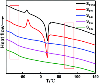
To study the effect of the TDI content on the thermodynamic behavior of the binder system, DSC tests were performed on binders with different γ values. Table 5 shows the glass transition temperature data for different γ values. The corresponding DSC and differential DSC curves are shown in Fig. 8.
Table 5 shows that the Tg of the soft segment is −79.33 °C when the TDI is absent in the system, which is close to the melting temperature of the pure PEG component. The melting endotherm of the PTMG also appears in the system. When γ is very small, the two polyether soft segments cannot be easily mixed only by relying on N100, and the phase separation degree of the soft segment polyether is greater. The melting endothermic peak of the system disappeared with increasing TDI content (γ). The soft segment polyether exhibited a single Tg, and the Tg of the soft segment gradually increased, indicating that the phase mixing degree of the soft and hard segments increased. In addition, the PEG and PTMG units passed through the TDI chemical connections, which are better blended to form a uniform system. However, the Tg of the hard segments changed slightly near 75 °C.
The endothermic peak in the system appears because the heating rate is higher than the cooling rate during the production of the sample, and the fraction of the free volume frozen in the glassy state when the melt is slowly cooled is small. Thus, the chain is not as heavy when the temperature is rapidly increased. Rows cannot quickly reach the equilibrium free volume fraction. The relaxation time of the segment rapidly decreases once the glass transition temperature is reached. The free volume suddenly increases to its equilibrium value. Thus, the DSC shows an endothermic peak.28
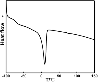
Fig. 9 and Table 5 show that the glass transition temperature of the soft segment in the HTPE binder is −74.17 °C, which is slightly lower than the glass transition temperature at −70.67 °C in the in situ-prepared HTPE binder. The similar values suggest that the in situ-prepared HTPE binder has a better degree of phase mixing and a lower glass transition temperature than the HTPE binder. Therefore, in situ-prepared HTPE binders are more viable than the HTPE binders based on the thermodynamics.
3.7 Application in propellant
From the analysis of the research results of these two binders, we can see that the mechanical properties of the in situ-prepared HTPE binder can reach those of the HTPE binder, and the tensile strength significantly improved. This laid the foundation for the application of in situ-prepared HTPE binder in propellants.The new in situ-prepared HTPE propellant was prepared according to the procedure described in Section 2.2. It is compact and free of pores and cracks. The process performance was good—the propellant slurry had a low viscosity and good leveling properties.
The mechanical properties of the in situ-prepared HTPE propellant and HTPE propellant are given in Table 6. The mechanical properties of the in situ-prepared HTPE propellant are greatly improved. The strength increased by over 200% and the elongation increased by about 135% compared to the HTPE propellant.
| Sample | σm (MPa) | εb (%) |
|---|---|---|
| In situ-prepared HTPE propellant | 0.81 | 50.1 |
| HTPE propellant | 0.26 | 21.3 |
To further study the differences between the mechanical properties of the two solid propellants, the microstructure surfaces of the in situ-prepared HTPE and the HTPE propellant specimens after tensile testing are shown in Fig. 10a and b, respectively. The HTPE propellant has a distinctly poor adhesion of the solid particle filler. More holes and bare particles are evident, indicating a greater amount of dewetting (Fig. 10b). The in situ-prepared HTPE propellant specimens did not form threads at the fracture surfaces after mechanical testing and seemed to have a significantly stronger binder–filler adhesion and fewer holes and bare particles, indicating that light dewetting occurred (Fig. 10a). The interactions of the bonding agent with the solid particle filler surfaces are presumably noncovalent by nature. This effect stems from the increase in the urethane bond density and the simultaneous increase in the cohesive energy density, which may have improved the adsorption of the binder on the polar surface of the filler particles. Thus, except for the mechanical properties of the in situ-prepared HTPE binder itself, adequate adhesion of the solid particles constituting the bulk of the composite material and the continuous binder matrix is critical for the good mechanical properties of the in situ-prepared HTPE propellant. This exciting result greatly enhances the feasibility of the proposed in situ preparation method and opens up a new realm for propellants.
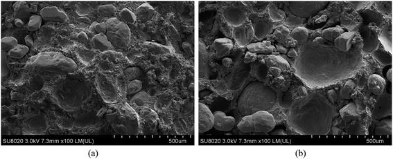 | ||
| Fig. 10 (a) Microstructure surfaces of composite solid propellants use in situ-prepared HTPE (a) and HTPE (b) as binder. | ||
4. Conclusions
We synthesized and characterized a novel in situ-prepared HTPE binder with PEG and PTMG functionalities. Uniaxial tensile tests were used to investigate their mechanical performances, and we concluded that the tensile strength of the in situ-prepared HTPE binder is significantly better than that of the HTPE binder. This indicates that the in situ-prepared HTPE has potential applications in the field of solid propellants versus HTPE.The crosslinking density of the in situ-prepared HTPE binder exhibited a large range of variation, and it increased and decreased with increasing PEG and TDI contents, respectively. The proportion of hydrogen bonding varies with the content of PEG and TDI and can reach 81.50%. Based on the statistical theory of elasticity, the integrities of the curing networks were analyzed, showing that the content of PEG and TDI affected the integrity of the curing networks.
DSC analysis of the in situ-prepared HTPE binder shows a lower glass transition point of −70.67 °C, which can meet the application conditions for the solid propellants. Compared to the HTPE propellant, the mechanical properties of the in situ-prepared HTPE propellant are greatly improved. This will lead to new architectures, and these polymers have many potential uses as propellants.
Conflicts of interest
The authors declare that they have no conflicts of interest.Acknowledgements
This work was funded by the Advanced Research Projects Agency (201920929091 and 40406010101).References
- G. Lakrishnan, A. Linan and F. Williams, J. Propul. Power, 1992, 8, 1167–1176 CrossRef.
- J. R. Goleniewski and J. A. Roberts, US Pat., 5348596, 1994.
- J. Q. Li, X. Z. Fan, Q. F. Tang, J. Z. Li, G. Q. Wang, X. N. Ren and Z. T. Mei, J. Solid Rocket Technol., 2019, 42, 597–602 Search PubMed.
- D. Q. Yan, D. D. Xu and J. G. Shi, J. Solid Rocket Technol., 2009, 32, 644–649 CAS.
- Q. F. Zhang and J. Q. Zhang, J. Energ. Mater., 2004, 12, 371–375 CAS.
- K. H. Kim, C. K. Kim, J. C. Yoo and J. J. Yoh, J. Propul. Power, 2011, 27, 822–827 CrossRef.
- X. Yang, X. Q. Zhi, B. L. Yang and J. J. Li, Chin. J. Explos. Propellants, 2016, 39, 84–89 Search PubMed.
- A. F. Zhang, H. Z. Zhang, H. C. Yang and X. D. Zhang, Chin. Sci. Bull., 1990, 35, 1881–1885 CAS.
- J. R. Goleniewski and J. A. Roberts, US Pat. 5783769A, 1998.
- G. Pruckmayr and R. B. Osborne, US Pat. 5284980A, 1994.
- I. C. De Witte and E. J. Goethals, Polym. Adv. Technol., 1999, 10, 287–292 CrossRef CAS.
- G. Pruckmayr and R. B. Osborne, US Pat. 5284980A, 1994.
- J. F. Neumer, US Pat. 5254744A, 1993.
- C. D. Wang, Y. J. Luo, M. Xia, X. M. Li and K. Z. Mao, J. Solid Rocket Technol., 2011, 34, 202–206 CAS.
- I. Hevus, A. Kohut and A. Voronov, Macromolecules, 2010, 43, 7488–7494 CrossRef CAS.
- S. Velankar and S. L. Cooper, Macromolecules, 2000, 31, 382–394 CrossRef.
- S. J. Chen, Q. Cao, B. Jing, Y. L. Cai, P. S. Liu and J. L. Hu, J. Appl. Polym. Sci., 2006, 102, 5224–5231 CrossRef CAS.
- Sudaryanto, T. Nishino, S. Asaoka and K. Nakamae, Int. J. Adhes. Adhes., 2001, 21, 71–75 CrossRef CAS.
- K. Z. Mao, M. Xia and Y. J. Luo, J. Elastomers Plast., 2016, 48, 546–560 CrossRef CAS.
- X. M. Wen, G. P. Zhang, K. K. Chen, S. Yuan and Y. J. Luo, Propellants, Explos., Pyrotech., 2020, 45, 1–12 CrossRef.
- Y. M. Ju, D. M. Kim and J. H. Lee, Biomaterials, 2000, 21, 683–691 CrossRef.
- H. G. Tattersall and G. Tappin, J. Mater. Sci., 1966, 1, 296–301 CrossRef.
- Y. J. Li, J. Li, S. Ma and Y. J. Luo, Int. J. Polym. Anal. Charact., 2016, 21, 495–503 CrossRef CAS.
- Y. Zhao, X. Zhang, W. Zhang, H. J. Xu, W. X. Xie, J. J. Du and Y. Z. Liu, J. Phys. Chem. A, 2016, 120, 765–770 CrossRef CAS PubMed.
- G. Q. Wang, C. X. Zhang, X. H. Guo and Z. Y. Ren, Spectrochim. Acta, Part A, 2008, 69, 407–412 CrossRef PubMed.
- T. R. Hesketh, J. W. C. Van Bogart and S. L. Cooper, Polym. Eng. Sci., 1980, 20, 190–197 CrossRef CAS.
- G. Wouter, S. Maria and D. Krijn, Macromolecules, 2001, 34, 1685–1693 CrossRef.
- A. Jeziorny, Acta Polym. Sin., 1986, 37, 137–141 CrossRef CAS.
| This journal is © The Royal Society of Chemistry 2020 |

