 Open Access Article
Theoretical and experimental investigations on the bulk photovoltaic effect in lead-free perovskites MASnI3 and FASnI3
Liping Peng *ab and
Wei Xiea
aCollege of Physics and Telecommunications, Huanggang Normal University, Huangzhou, 438000, P. R. China. E-mail: pengliping@hgnu.edu.cn
bCollege of Materials and Engineering Science, Huazhong University of Science and Technology, Wuhan, 430074, P. R. China
First published on 14th April 2020
Abstract
Perovskite solar cells based on the lead free hybrid organic–inorganic CH3NH3SnI3 (MASnI3) and CH4N2SnI3 (FASnI3) perovskites were fabricated, and the photoelectric conversion efficiency (PCE) was assessed. FASnI3's PCE was higher than MASnI3's efficiency. To study the different photovoltaic properties, we calculated their structural, electronic, and optical properties using density functional theory via the Perdew–Burke–Ernzerhof and spin–orbit coupling (PBE-SOC) methods. The results show that FASnI3 exhibits an appropriate band gap, substantial stability, marked optical properties, and significant hole and electron conductive behavior compared with MASnI3. The interaction of organic cations (FA+) with the inorganic framework of FASnI3 was stronger than that with MASnI3, so they affected the band length and band angle distribution, causing the structure of the FASnI3 and MASnI3 to change. The calculations also demonstrated that energy splitting was evident in FASnI3 due to the spin–orbit coupling effect, however, it was moderate in MASnI3, which was caused by the H bond effect. This research not only furthers the understanding of these functional materials, but also can assist the development of highly efficient and stable non-lead perovskite solar cells.
1. Introduction
The photoelectric conversion efficiency (PCE) of organic–inorganic perovskite solar cells (PSCs) has rapidly increased from 3.8% to 25.2%.1 Perovskite solar cells will likely be important for the next generation of solar cells. However, an important issue must be solved for their application. The lead (Pb) in perovskite materials is toxic to the human body and environmentally unfriendly, so the preparation of lead-free perovskite solar cells has become an important problem.Because tin (Sn) and Pb belong to the same family, they possess the same number of valence electrons. They both have two electrons in the outermost orbit, and the Sn is the first to replace the Pb in the perovskite field. Many studies have focused on MASnI3 perovskite materials.2–8 L. J. Wu et al. calculated an energy gap of 1.3 eV,5 similar to the experimental results.6,7 MASnI3 perovskite has a similar structure to MAPbI3 (although in different temperature ranges). Previous reports also indicated that MASnI3 has a high mobility and small effective mass.8 However, for Sn-based perovskites, the main problem is that their efficiencies and stabilities are lower than MAPbI3 perovskite solar cells. Sn-based perovskites are sensitive to oxygen and atmospheric moisture. Therefore, the instability of MASnI3 is related to the oxidation of Sn ion. Changing Sn2+ to Sn4+ may cause a structural transformation, reducing the photovoltaic performance of MASnI3.9
Some of research groups recently reported that when MA cation was replaced by FA cation, its band can reached 1.41 eV,10 and the FASnI3 had higher mobility and stability than MASnI3. Y. Liao et al. prepared low-dimensional tin-based perovskites with PEA materials. These types of perovskite solar cells have a PCE of 5.94% after 100 h in a glovebox.11 Ke et al.12 reported that the PCE of FASnI3 reached 7.14% through 10% ethylenediammonium (en) doping, and the PCE was 6.37% after storing for 1000 h. Due to the high PCE and long-term stability of lead-free perovskite, using SnF2 is an effective method of producing advanced FASnI3 film. Zong et al.13 reported that SnF2 remained in the grain boundaries of polycrystalline films when SnF2·3FACl was added to (FAPbI3)0.7(CsSnI3)0.3 precursors. Under high humidity or strong light exposure, the structural phase was stable through utilizing additive, and SnF2 played a significant role in the device, but addition of excess SnF2 has also a tendency to form a separate phase on the surface of perovskite films. In addition, some literatures14,15 have analyzed the reason why the FASnI3's PCE was higher than the MASnI3's efficiency, however, these viewpoints are more and different.
To assess the effect of replacing MA ion with FA ion, we fabricated MASnI3 and FASnI3 solar cells and measured their PCE. We then calculated the electrical structure properties of the tetragonal phase (I4/mcm space group). We also compared with the differences in the optical absorption, stability, and electron and hole transport behavior of FASnI3 and MASnI3. We measured the antibonding coupling effect between the s orbit of Sn atoms and the p orbit of FA ions and MA ions, using first-principles calculations to elucidate the photoelectric properties of FASnI3 and MASnI3.
2. Experiment and calculations
2.1 Preparation of the perovskite materials
Formamidinium iodide tin (FASnI), methylamine iodine tin (MASnI), and SnI2 were purchased from Sigma-Aldrich Company. The SnI2 and FASnI (or MASnI) (1 M![[thin space (1/6-em)]](https://www.rsc.org/images/entities/char_2009.gif) :
:![[thin space (1/6-em)]](https://www.rsc.org/images/entities/char_2009.gif) 1 M) were dissolved in a solvent mixture of N,N-dimethylformamide (DMF, Sigma-Aldrich) as the precursor solution. The precursor solution was stirred at 80 °C for 12 h. The mass concentration was 30 wt% of the polymeric precursor solution. A hole transport layer was created using PEDOT:PSS (PH1000, Sigma-Aldrich) purchased from Bayer (Germany). An electron transport layer was produced using PCBM obtained from Banhe Technology Co. The phenyl-C60-butyric acid methyl ester (PCBM) concentration was 20 mg mL−1. This was dissolved in chlorobenzene (CB, Sigma-Aldrich) and stirred at 80 °C for 6 h. ITO and silver (Ag) anodes and cathodes were used, respectively. The entire structure was ITO/PEDOT:PSS/FASnI3(or MASnI3)/PCBM/PEI/Ag, the device's structure is shown in Fig. 1.
1 M) were dissolved in a solvent mixture of N,N-dimethylformamide (DMF, Sigma-Aldrich) as the precursor solution. The precursor solution was stirred at 80 °C for 12 h. The mass concentration was 30 wt% of the polymeric precursor solution. A hole transport layer was created using PEDOT:PSS (PH1000, Sigma-Aldrich) purchased from Bayer (Germany). An electron transport layer was produced using PCBM obtained from Banhe Technology Co. The phenyl-C60-butyric acid methyl ester (PCBM) concentration was 20 mg mL−1. This was dissolved in chlorobenzene (CB, Sigma-Aldrich) and stirred at 80 °C for 6 h. ITO and silver (Ag) anodes and cathodes were used, respectively. The entire structure was ITO/PEDOT:PSS/FASnI3(or MASnI3)/PCBM/PEI/Ag, the device's structure is shown in Fig. 1.
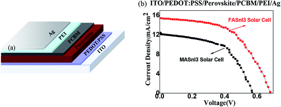 | ||
| Fig. 1 (a) Device's structure diagram, and (b) the I–V characteristics of the perovskite solar cells with the MASnI3 and FASnI3. | ||
2.2 Device fabrication
First, laser-patterned, ITO-coated glass substrates were cleaned via ultrasonic oscillation in an aqueous alkaline washing solution for 15 min. Deionized water, ethanol, and acetone were used to rinse the substrates, respectively. ITO was treated with ultraviolet light in O3 for 30 min. PEDOT:PSS was deposited by spin-coating at 5000 r.p.m. for 30 s to obtain a thickness of 40 nm. The prepared perovskite was then spin-coated on the PEDOT:PSS thin film at 1000 rpm for 10 s, followed by 4000 rpm for 35 s in a nitrogen atmosphere. The thin film was immediately annealed at 70 °C for 80 min. After cooling, PC60BM (20 mg mL−1 in chlorobenzene) was spin-coated on top of the perovskite film at 2000 rpm for 45 s, followed by spin-coating an interface-modifying layer of PEIE (0.1 wt% in anhydride 2-propanol) at 5000 rpm for 60 s. Finally, 80 nm thick Ag layers were thermally deposited as the top electrodes under a vacuum of 4 × 10⁻⁴ Pa to fabricate perovskite solar cells with an area of 9 mm2. The FASnI3 and MASnI3 devices were encapsulated by epoxy resin in a glove box for experimental measurements.2.3 Parameter setting
For our calculations, we adopted the Vienna ab initio simulation package (VASP) based on the first-principles calculations methods.16 We used the projected augmented wave (PAW) method to measure the ion–electron exchange broadband energy.17,18 The plane wave basis energy cut-off was 500 eV.19 We used the Sn 4d5s5p, I 5s5p, C 2s2p, N 2s2p, and H 1s states as the valence configurations. All of the atoms in these structures were allowed to relax to less than 1.0× 10⁻⁵ eV per atom. The Brillouinzone integrations were calculated using Monkhorst–Pack grids20 with 6 × 6 × 6 meshes. Generalized gradient approximations (GGA) combined with Perdew–Burke–Ernzerhof (PBE) functions were used for the exchange correlation.21PBE significantly underestimates the band gap of halide perovskites. For example, the calculated PBE band gap is about 0.6 eV for MAPbI3, much smaller than the experimental gap of 1.50 eV. To correct the band gap underestimation, a hybrid functional such as the Heyd–Scuseria–Ernzerhof (HSE06) functional needs to be used.22 The most advanced calculation approach is to use spin–orbit coupling (SOC + HSE06) calculation. However, so far, SOC + HSE06 calculations is very time consuming and can only be feasible for calculations with small unit cells.23,24 It is well known that the van der Waals (vdW) correction has an important effect on perovskite systems with weak interactions.25 If the effect of non-local vdW interactions on perovskite systems is neglected,26 then the change between the theoretical lattice constants and the experimental data is less than 1–2% when the non-local vdW function is employed. Therefore, to obtain accurate values, our calculations used a vdW correction based on the GGA-PBE method.27,28 In addition, the MAPbI3 has a spin–orbit coupling SOC effect since it is a spin-dependent relativistic correction in origin and is more prominent in heavy elements such as Pb and Sn atoms.29 Even et al. reported a significant SOC effect on the band structure of Pb-based perovskite with a reduced band gap by including a large splitting of the first degenerated conduction bands,30,31 so the SOC effect must be considered in the FASnI3 and MASnI3. In this work, we used PBE with the SOC method (PBE + SOC) to calculate the band gap and density of state. For the MASnI3, we adopted the lattice parameters of a tetragonal phase structure. Its lattice parameters are a = 8.73 Å, b = 8.95 Å, and c = 12.50 Å.14 For the FASnI3 perovskite, we adopted a tetragonal phase structure with lattice parameters of a = 8.79 Å, b = 8.99 Å, and c = 12.83 Å.15 Firstly, we optimized the crystal geometry structure by the energy lowest theory, after then, we calculated and analyzed the energy band and density of state base on the optimized results, although the lattice parameters don't derive their lattice vectors in a self-consistent manner,32 we think the way is reasonable. We also calculated the optical properties and dielectric function of the two perovskite materials. The optical absorption spectra was A(ω) = 1 − e−α(ω)Δz (Δz is the unit cell size), and the dielectric function was ε(ω) = ε1(ω) + iε2(ω), where ε1(ω) is the real part of the dielectric function and ε2(ω) is the imaginary part of the dielectric function, ε1(ω) was evaluated from the imaginary part ε2(ω) using the Kramers–Kronig relation, while ε2(ω) was obtained from the momentum matrix elements between the occupied and unoccupied wave functions.33,34
3. Results and discussion
3.1 I–V characteristics in perovskite solar cells with MASnI3 and FASnI3
Fig. 1 shows the current–voltage (I–V) curve characteristics of the MASnI3 and FASnI3 perovskite solar cells. The PCE of the FASnI3 perovskite solar cell is greater than that of the MASnI3. The PCE reached a maximum of 5.51%. Table 1 shows that the greater PCE in the FASnI3 was mainly due to the rapidly increased short-circuit current (Jsc). Compared with the MASnI3, the Jsc was only 12.47 mA cm−2 when the FA cation replaced the MA cation. The Jsc increased quickly, and the maximum of Jsc was 15.36 mA cm−2. This demonstrated that the interior charge transport properties increased after the FA cation replaced the MA cation. We think the effect come from the spin–orbit coupling effect, because the effect of spin–orbit coupling is different on the MASnI3 and FASnI3, when the light field interacts with the electrons, they generate the polarization field is also different, thus increasing the photocurrent density and the short circuit current in the solar cell, thus improving the PCE of the solar cell. In addition, under the same conditions, the open-circuit voltage (Voc) of FASnI3 was bigger than the MASnI3, the Voc of FASnI3 solar cell was 0.64 V, and the Voc of MASnI3 was 0.57 V. In our experiment, we found that the Voc was high in the FASnI3 without SnF2, we thought it came from the effect of the perovskite thin film morphology, because addition of SnF2 has a tendency to form a separate phase on the surface of perovskite films, it is not good for the morphology, it will produce a charge accumulation,35 the thin film morphology of FASnI3 without SnF2 is better than the thin film with SnF2, it reduced the charge accumulation at interface, and reduced background carrier density, which causes the recombination loss.| Materials | Voc (V) | Jsc (mA cm−2) | FF | PCE (%) |
|---|---|---|---|---|
| MASnI3 | 0.57 | 12.47 | 0.44 | 3.13 |
| FASnI3 | 0.64 | 15.36 | 0.56 | 5.51 |
3.2 Structures and formation energies
Fig. 2 shows the stable geometries after optimization. In the MASnI3 and FASnI3 systems, six I atoms surrounded the Sn atoms. Two I atoms are located in the apical direction and the other four in the equatorial direction. MA+ or FA+ ions filled in the octahedral cages, as demonstrated in Fig. 2. It had distorted geometries. The distortion degree of the FASnI3 was greater than that of the MASnI3 perovskite, which may have been caused by the high ionic conductivity properties, the ionic conductivity properties induce the distortion degree of perovskite main reason was the ion's accumulation effect, it can produce a strong built-in electrical field in the MASnI3 and FASnI3 bulk, at the same time, it bring an strong polarization effect, the polarization effect can change the interaction force between molecule and molecule, thus bring the structure change of single crystal, the change of crystal structure induce the distortion degree of perovskite. The optimized lattice constants and available MASnI3 and FASnI3 experimental data are shown in Table 2. There were large volume contractions of 1031.86 Å3 to 971.20 Å3 from FA+ to MA+. Specifically, the lattice constriction changed along a and c directions, which was caused by the reduction in the organic framework ion radii.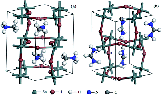 | ||
| Fig. 2 Optimized stable geometries of (a) MASnI3, (b) FASnI3 (brown: I; dark gray: Sn; gray: C; blue: N; white: H). | ||
In the b direction, the lattice structure had an elongation trend when the organic ion changed from MA+ to FA+, which was caused by the weak ionic bond interaction between the I ions and H ions. The angular values of α, β, and γ deviated from 90°, which was caused by structural deformations. The lattice parameters calculated using the PBE + SOC method were in good agreement with experimental data provided by D. B. Mitzi and K. Liang et al., with a deviation of 1–2%.36,37
To further explore the equilibrium structures of the perovskites, the bond lengths and angles of the MASnI3 and FASnI3 systems were calculated as shown in Table 3. Table 3 demonstrates that the minimum bond length of the HC–I (bond length of C–I bond) was larger than that of the HN–I (bond length of N–I bond), which indicates that the H–N atom in the organic cation (FA+ and MA+) was closer to the Sn–I chain than the H–C atom. The H–N atom had a stronger attraction to the halogen atom by vdW forces because the H–N atom had a larger dipole moment than the H–C atom. It was obvious that the hydrogen bond between the organic cation and the inorganic framework had a considerable effect on the geometry of the investigated systems (in this paper, the hydrogen bond is defined as the bond length between the ammonium hydrogen atoms and the halogen atoms with a value less than 2.8 Å). Compared with the FASnI3 and MASnI3 systems, the interaction effect of the FA+ organic cation and the inorganic framework was stronger in the FASnI3 than in the MASnI3, so it affected the bond length and bond angle's distribution, changing the structure of the FASnI3 and MASnI3. The bond lengths of the Sn–I in both the equatorial and apical directions had a similar trend to the lattice parameters. The average Sn–I bond lengths were 3.13 Å and 3.25 Å for the MASnI3 and FASnI3, respectively. Both the bond lengths and the angles of the Sn–I were significantly affected by the distribution of the MA+ and FA+.
| Type | MASnI3 | FASnI3 |
|---|---|---|
| HN–I | 2.61–3.53 | 2.81–3.73 |
| HC–I | 3.23–3.46 | 3.32–3.69 |
| Sn–I1 (equatorial) | 2.82–3.64 | 3.17–3.24 |
| Sn–I2 (apical) | 2.82–3.63 | 3.17–3.25 |
| Sn–I–Sn (equatorial) | 153–167 | 150–170 |
| Sn–I–Sn (apical) | 167–168 | 170–178 |
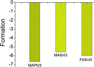
The stability of MASnI3 and FASnI3 perovskites is the bottleneck question for the development of perovskite solar cell applications. The stability can be estimated from the formation energy. Based on the UV-vis spectra and the X-ray photoelectron spectroscopy results, and the formation energy was expressed using the following equations:
| MAI + SnI2 → MASnI3 | (1) |
| FAI + SnI2 → FASnI3 | (2) |
| Ef = E(MASnI3) − E(MAI) − E(SnI2) | (3) |
| Ef = E(FASnI3) − E(FAI) − E(SnI2) | (4) |
Here, we discussed the stability only from the atom structure in the microstructure, and not discussed the stability on the macro-level. The crystal is regarded as a perfect crystal in the ideal state, which is different from the macroscopic stability. We think the internal atom structure certainly will affect the perovskite materials to the influence of external environment. MAPbI3 and FASnI3 had little difference in their formation energy values, indicating that the FASnI3 had a similar stability to the MAPbI3. Based on the analysis of the structural properties and formation energies of the MASnI3 and FASnI3 systems, it was clear that weak interactions between the cation FA+ framework had an important effect on determining the equilibrium structures and stabilities of the perovskites.
3.3 Electronic properties and effective mass
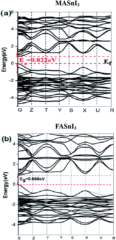
To provide a rationale for the observed band-gap and spectral variation, we investigated both structural. The energy band structure is an important factor for determining many physical properties such as absorption, photoconductivity, and electroluminescence. Fig. 4 shows the energy band structure of the MASnI3 and FASnI3 calculated using the PBE + SOC methods. The band gap of the MASnI3 obtained using the PBE + SOC method was 0.882 eV, which did not match well with the experimental result of 1.30 eV.38 The band gap of the FASnI3 calculated using the PBE + SOC method was 0.868 eV, lower than the previous experimental result of 1.41 eV10 because the PBE calculation used many approximate treatments to underrate the band gap.39 A SOC calculation performed for MASnI3 and FASnI3 at the geometry and cell parameters, while rescaling the MASnI3 and FASnI3 coordinates to the experimental MASnI3 and FASnI3 cell parameters, led to a 0.42 eV and a 0.55 eV band-gap decrease compared to MASnI3 and FASnI3, respectively, as estimated by PBE + SOC. This data suggests that out of the 0.42 eV and a 0.55 eV calculated band-gap difference, ∼0.2 eV are due to SOC effect, such as the different degree of tilting of the MI6 octahedra by the SOC effect, usually, the SOC calculation can underrate the band gap.40,41 SOC + HSE06 calculation is very time consuming and can only be feasible for calculations with small unit cells. In our study, most calculations require the use of large super cells. For these calculations, it is not possible to consider SOC + HSE06 or SOC − GW. Therefore, here we select the van der Waals (vdW) correction + PBE + SOC to the calculate of optical properties and electron and hole transport behavior of MASnI3 and FASnI3.For the spin–orbit coupling effects, the SOC had a dramatic effect on the conduction band region, with a sharp reduction in the bottom of the conduction band. This reduction was caused by the splitting of the conduction band into a two-fold degenerated state |1/2, ±1/2〉 corresponding to light electrons and four-fold degenerated states |3/2, ±3/2〉, |3/2, ±1/2〉 corresponding to heavy electrons at the G point.42 It follows that the band gaps decreased to 0.882 eV in the MASnI3 and 0.868 eV in the FASnI3, much lower than the experimental results of MASnI3 1.30 eV and FASnI3 1.41 eV.5,10 This means that the SOC had a rather strong energy-splitting effect on the band structure of the MASnI3 and FASnI3 perovskites. Comparing Fig. 4 (a) and (b), the SOC had a dramatic effect on the conduction band region with a sharp reduction in the bottom of the conduction band in the FASnI3. Fig. 4(a) clearly shows that the bands of the MASnI3's CBM and CBM + 1 (we defined the first and the second bands from the bottom of the conduction bands as CBM and CBM + 1, respectively) began to split into two bands along the Y to R directions, but both bands over lapped again in the region near the Z point. However, in the FASnI3 energy band calculated using the SOC effect (see Fig. 4(b)), both the CBM and CBM + 1 had two isolated bands along the G to Y directions after the energy splitting, and the CBM still had a single line after the influence of the SOC effect. We speculate that the SOC had a strong effect in the FASnI3. We will discuss how the SOC affected the valence bands in the density of state section.
Since the photo-generated electrons and holes in the perovskites thermally relaxed to the CBM and VBM, respectively, a small effective mass facilitated the transportation of the electrons and holes. The effective masses of the  and
and  were calculated via the following equation.43
 | (5) |
The effective masses of the MASnI3 and FASnI3 calculated using the PBE-SOC methods agreed well with previous reports.45,46 Thus, in terms of the FASnI3, broadly speaking, it had better electron and hole transport than the MASnI3 under similar conditions, so it can be considered a good choice to substitute for MASnI3.
To further understand the electronic structures of the two perovskites, the density of states were analyzed. The DOS structures obtained using the SOC calculations are shown in Fig. 5. The projected density of states (PDOS) in Fig. 5 reflected the calculation of the PBE-SOC structures. The peak intensities of their PDOS with the SOC effect were weak, which are barely visible in Fig. 5. Comparing the partial density of states (PDOS) of the MASnI3 and FASnI3 structures, a shift in the SOC-PDOS was reflected in the region near the zero point showing a shrunken band gap. This phenomenon was more obvious in the FASnI3, in which both the valence bands and conduction bands shifted toward the zero point. The FASnI3 had a larger spin–orbit coupling constant than the MASnI3. Both structures had two peaks in the valence band maximum (VBM). The peak intensities of the MASnI3 were weaker than those of the FASnI3 as obtained using the PBE + SOC calculation. The SOC also may have caused the weak energy splitting in the VBM. As shown in Fig. 5, the main contribution to the VBM was from the 5p orbitals of the I atoms with an overlap in the s orbitals of the Sn atoms, while the CBM was dominated by the p orbitals of the Sn atoms partly hybridized with the I orbitals. The MA+ and FA+ cations also contributed slightly to the CBM and VBM around the Fermi energy level (EFermi was adjusted to the zero point).
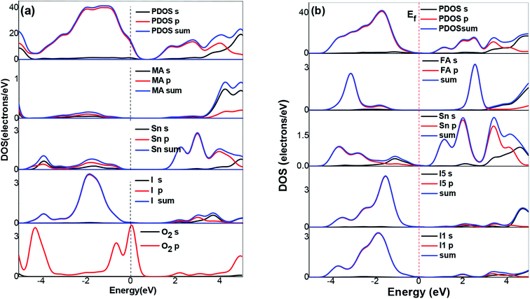 | ||
| Fig. 5 DOS structures of (a) MASnI3, (b) FASnI3. The dashed and solid lines represent the results calculated with the SOC effect, respectively. | ||
In the Partial Density of States (PDOS) in the FASnI3 perovskites, the SOC results showed a strong shift on the VBM edges. The peak splitting in the valence bands of the FASnI3 was not similar to those in the MASnI3. However, the SOC-PDOS of the FASnI3showed a complete overlap with the PDOS using the SOC correction. This means that the SOC also caused strong energy splitting in the valence bands, confirming the conclusion drawn from the FASnI3 results. More importantly, the different degrees of peak splitting in the valence bands also indicated that the SOC had some effects on the interaction between the organic cations (FA+ and MA+) and H bonds. The main contributions to the VBM were from the p orbitals in the C atoms, with an overlap in the s orbitals of the H atoms. These features can be seen in the charge densities of the VBM shown in the left and right panels of Fig. 6. FASnI3 is used as an example with more details. The green iso surfaces in the VBM were distributed in the 5p orbitals of the I and s orbitals of FA ions, while in the CBM, they were with the 4p orbitals in the Sn. This means that the electrons were distributed around the CBM and the holes were around the VBM. These results demonstrate that the electrons and holes separated effectively between the CBM and VBM since the electrons on the 5p orbitals of the I and the 4s orbitals of the Sn were excited to the 4p orbitals of the Sn under photoexcitation. Both the total charge density of the MASnI3 shown in the left panel of Fig. 6(a) and the PDOS in Fig. 5 indicate that the charge accumulated in the region between the I atoms and MA+ matrix, confirming the formation of the H–I hydrogen bonds. A similar situation also occurred in the FASnI3, as shown in Fig. 6(b). To better elucidate the coupling between the MA+ and FA+ and the Sn–I chain, contour plots of the electrostatic potential were drawn for specific surfaces as shown in Fig. 7(a and b). The coupling action was weak since there was no many electrons orbital overlap between the cation MA+ and FA+ and the I atoms. This means that there was not a strong covalent interaction between the organic molecules and the I atoms. But there were strong overlaps between the Sn and I atoms, demonstrating the strong covalent bonding in the Sn–I chains. The weak contour lines between the H and I also indicated that a weak interaction occurred between the two types of atoms, forming an H–I hydrogen bond. The electrostatic potential of the VBM was mainly the anti-bonding component of the hybridization between the s orbitals of the Sn and the p orbitals of the I, while the CBM was almost a non-bonding state dominated by the p orbitals of the Sn.
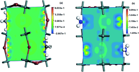 | ||
| Fig. 6 Charge density of MASnI3 and FASnI3, (a) the left panel is MASnI3 (110) surface's charge density, (b) the right panel is FASnI3 (110) surface's charge density. | ||
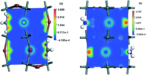 | ||
| Fig. 7 Charge difference densities of some CBM and VBM bands of (a) MASnI3 (110) surface and (b) FASnI3 (110) surface. | ||
For more insight into the electron distribution on the bands near the VBMs and CBMs of the MASnI3 and FASnI3, the charge difference densities are displayed in Fig. 7. The charged is tribution was primarily located in the Sn and I atoms, and the electron density increased as the valence bands increased in the FASnI3. Compared with the MASnI3, the densities of the FASnI3 accumulated around the p orbitals of the Sn atoms with little difference as the band energy changed, indicating that the electrons moved from the valence bands to the conduction bands, filling the holes with VBMs. As for the appropriate band gap between the CBM and VBM, it caused the electrons to inject into the conduction bands, thus increasing the photovoltaic efficiency.
3.4 Optical properties
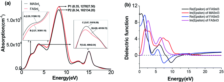
Fig. 8 shows the optical absorption coefficients of the MASnI3 and FASnI3 calculated using the equation A(ω) = 1 − e−α(ω)Δz.47 This result agrees well with those of Feng et al. using the TDDFT method.48 As shown in Fig. 8(a), the FASnI3 had the strongest absorption in the entire visible solar spectrum, and the spectrum of MASnI3 showed a blue shift with respect to the FASnI3, the FASnI3 had a large red shift, and the coefficient was better than the MASnI3. Unlike the MAPbI3, the MASnI3 and FASnI3 had weak absorption in the ultraviolet spectrum, also agreeing with the previously discussed trend in the band gap. For the absorption spectrum of the MASnI3 and FASnI3 perovskites in the visible light region, the FASnI3 absorption coefficient was better than that of the MASnI3. According to the absorption spectra of the FASnI3 in ref. 49, it has an absorption of 2.0–4.0 eV in the 310–620 nm spectrum region, the same trend as our results. The absorption of the FASnI3 was in good agreement with the experimental results. To further study the solar energy-harvesting properties, we calculated the dielectric function of the two perovskites. The real and imaginary parts of the dielectric function are shown in Fig. 8(b). For the computed structures, the dielectric spectra in the imaginary parts demonstrated two peaks below 500 nm and then showed a downward trend. Among the two imaginary parts, the computed intensities of the FASnI3 were higher than the MASnI3 structures, corresponding to the largest absorption coefficient as displayed in Fig. 8(a). For the real parts of the FASnI3, the absorption was nearly 5–7 eV, demonstrating that they had strong absorption in the ultraviolet spectrum. The second absorption was in the range of 9–10 eV in the calculated dielectric spectra. This absorption was basically located at the near ultraviolet spectrum. From the calculated dielectric spectra, the FASnI3 had a good overlap with the MASnI3 in both the imaginary and real parts. Thus, the FASnI3 exhibited good solar energy absorption ability in the visible light spectrum.4. Conclusions
In this study, we fabricated FASnI3 and MASnI3 perovskite solar cells and measured their PCE. The PCE of the FASnI3 was 5.51%, higher than that of the MASnI3. We used the SOC effect combined with the PBE function to analyze the structural, electronic, and optical properties of MASnI3 and FASnI3 perovskites. The results demonstrate that unlike the evident SOC effects in the FASnI3 compared with the MASnI3, the SOC affected the band length and band angle and reduced the organic cation radius, which both affected the equatorial and apical directions with a similar trend in the lattice parameters, changing the structure. The effect of the organic cation (FA+) and inorganic framework was stronger in the FASnI3 than in the MASnI3, affecting the band length and band angle distribution and changing the structure of the FASnI3 and MASnI3. Based on the analysis of the structural properties and the formation energies of the MASnI3 and FASnI3, it was clear that weak interactions between the cation FA+ or MA+ and the inorganic framework had an important effect on determining the equilibrium structures and the stabilities of the perovskites. In addition, the effective masses of the FASnI3 had better electron and hole transport properties than the MASnI3 under similar conditions. The optical properties and dielectric function of the FASnI3 had a similar absorption ability to the MASnI3. These results suggest that FASnI3 may be a competitive and environmentally friendly alternative to MASnI3 for efficient perovskite solar cells.Conflicts of interest
There are no conflicts to declare.Acknowledgements
The authors gratefully acknowledge financial support from the Scientific Research Project of Hubei Education Department (Grant No. D20182901), Breeding Programs Funds for Huanggang Normal University (Grant No. 04201813603), and Huanggang Science and Technology Project. (Grant No. XQYF2018000013).References
- NREL, National Renewable Energy Laboratory, https://baijiahaobaidu.com/s?id=1641007748124043683%26wfr=spider%26for=pc.
- F. Hao, C. C. Stoumpos, D. H. Cao, R. P. H. Chang and M. G. Kanatzidis, Lead-free solid-state organic–inorganic halide perovskite solar cells, Nat. Photonics, 2015, 8, 489 CrossRef.
- N. K. Noel, S. D. Stranks, A. Abate, C. Wehrenfennig, S. Guarnera, A. A. Haghighirad, A. Sadhanala, G. E. Eperon, S. K. Pathak, M. B. Johnston, A. Petrozza, L. M. Herz and H. J. Snaith, Lead-free organic–inorganic tin halide perovskites for photovoltaic applications, Energy Environ. Sci., 2014, 7, 3061 RSC.
- B. Wang, X. Xiao and T. Chen, Perovskite photovoltaics: a high-efficiency newcomer to the solar cell family, Nanoscale, 2014, 6, 12287 RSC.
- L. J. Wu, Y. Q. Zhao, C. W. Chen, L. Z. Wang, B. Liu and M. Q. Cai, First-principles hybrid functional study of the electronic structure and charge carrier mobility in perovskite CH3NH3SnI3, Chin. Phys. B, 2016, 25, 107202 CrossRef.
- F. Hao, C. C. Stoumpos, P. J. Guo, N. J. Zhou, T. J. Marks, R. P. H. Chang and M. G. Kanatzidis, Solvent-mediated crystallization of CH3NH3SnI3 films for heterojunction depleted perovskite solar cells, J. Am. Chem. Soc., 2015, 137, 11445 CrossRef CAS PubMed.
- C. C. Stoumpos, C. D. Malliakas and M. G. Kanatzidis, Semiconducting Tin and Lead Iodide Perovskites with Organic Cations: Phase Transitions, High Mobilities, and Near-Infrared Photoluminescent Properties, Inorg. Chem., 2013, 52, 9019 CrossRef CAS PubMed.
- I. Chung, B. Lee, J. He, R. P. H. Chang and M. G. Kanatzidis, All-solid-state dye-sensitized solar cells with high efficiency, Nature, 2012, 485, 486 CrossRef CAS PubMed.
- Z. Xiao, H. Lei, X. Zhang, Y. Zhou, H. Hosono and T. Kamiya, Ligand-Hole in [SnI6] Unit and Origin of Band Gap in Photovoltaic Perovskite Variant Cs2SnI6, Bull. Chem. Soc. Jpn., 2015, 88, 1250 CrossRef CAS.
- T. M. Koh, T. Krishnamoorthy, N. Yantara, C. L. Shi, L. We, P. P. Boix, A. C. Grimsdale, S. G. Mhaisalkar and N. Mathews, Formamidinium tin-based perovskite with low Eg for photovoltaic applications, J. Mater. Chem. A, 2015, 3, 14996 RSC.
- Y. Liao, H. Liu and W. Zhou, et. al., Highly Oriented Low-Dimensional Tin Halide Perovskites with Enhanced Stability and Photovoltaic Performance, J. Am. Chem. Soc., 2017, 139, 6693 CrossRef CAS PubMed.
- W. Ke, C. C. Stoumpos and M. Zhu, et. al., Enhanced photovoltaic performance and stability with a new type of hollow 3D perovskite {en}FASnI3, Sci. Adv., 2017, 3, e1701293 CrossRef PubMed.
- Y. Zong, Z. Zhou and M. Chen, et. al., Lewis-Adduct Mediated Grain-Boundary Functionalization for Efficient Ideal-Bandgap Perovskite Solar Cells with Superior Stability, Adv. Energy Mater., 2018, 1800997 CrossRef.
- T. Shi, H. S. Zhang, W. Meng, Q. Teng, M. Liu, X. Yang, Y. Yan, H. L. Yip and Y. J. Zhao, Effects of Organic Cation on the Defect Physics of Tin Halide Perovskites, J. Mater. Chem. A, 2017, 5, 15124 RSC.
- S. Tao, I. Schmidt, G. Brocks, J. Jiang, I. Tranca, K. Meerholz and S. Olthof, Absolute energy level positions in tin and lead-based halide perovskites, Nat. Commun., 2019, 10, 2560 CrossRef PubMed.
- G. Kresse and J. Furthmuller, Efficient iterative schemes for ab initio total-energy calculations using a plane-wave basis set, Phys. Rev. B: Condens. Matter Mater. Phys., 1996, 54, 11169 CrossRef CAS PubMed.
- P. E. Blöchl and A. Togni, First-Principles Investigation of Enantioselective Catalysis: Asymmetric Allylic Amination with Pd Complexes Bearing P,N-Ligands, Phys. Rev. B: Condens. Matter Mater. Phys., 1996, 50, 17953 CrossRef PubMed.
- G. Kresse and D. Joubert, From ultrasoft pseudopotentials to the projector augmented-wave method, Phys. Rev. B: Condens. Matter Mater. Phys., 1999, 59, 1758 CrossRef CAS.
- D. Vanderbilt, Soft self-consistent pseudopotentials in a generalized eigenvalue formalism, Phys. Rev. B: Condens. Matter Mater. Phys., 1990, 41, 7892 CrossRef PubMed.
- H. J. Monkhorst and J. D. Pack, Special points for Brillouin-zone integrations, Phys. Rev. B: Condens. Matter Mater. Phys., 1976, 13, 5188 CrossRef.
- J. P. Perdew, K. Burke and M. Ernzerhof, Generalized Gradient Approximation Made Simple, Phys. Rev. Lett., 1996, 77, 3865 CrossRef CAS PubMed.
- J. Heyd, G. E. Scuseria and M. Ernzerhof, Hybrid Functionals Based on a Screened Coulomb Potential, J. Chem. Phys., 2003, 118, 8207–8215 CrossRef CAS.
- W. Geng, L. Zhang, Y. N. Zhang, W. M. Lau and L. M. Liu, First-Principles Study of Lead Iodide Perovskite Tetragonal and Orthorhombic Phases for Photovoltaics, J. Phys. Chem. C, 2014, 118, 19565–19571 CrossRef CAS.
- J. Varignon, M. Bibes and A. Zunger, Origins versus fingerprints of the Jahn-Teller effect ind-electron ABX3 perovskites, Phys. Rev. Res. Int., 2019, 1, 033131 CrossRef.
- Y. Wang, T. Gould, J. F. Dobson, H. Zhang, H. Yang, X. Yao and H. Zhao, Density functional theory analysis of structural and electronic properties of orthorhombic perovskite CH3NH3PbI3, Phys. Chem. Chem. Phys., 2014, 16, 1424 RSC.
- Y. Andersson, D. C. Langreth and B. I. Lundqvist, van der Waals Interactions in Density-Functional Theory, Phys. Rev. Lett., 1996, 76, 102 CrossRef CAS PubMed.
- S. Grimme, Semiempirical GGA-type density functional constructed with a long-range dispersion correction, J. Comput. Chem., 2006, 27, 1787 CrossRef CAS PubMed.
- E. Mosconi, A. Amat, M. K. Nazeeruddin, M. Grätzel and F. De Angelis, First-Principles Modeling of Mixed Halide Organometal Perovskites for Photovoltaic Applications, J. Phys. Chem. C, 2013, 117, 13902 CrossRef CAS.
- F. Neese, Efficient and accurate approximations to the molecular spin-orbit coupling operator and their use in molecular g-tensor calculations, J. Chem. Phys., 2005, 122, 034107 CrossRef PubMed.
- J. Even, L. Pedesseau, J. M. Jancu and C. Katan, Importance of Spin-Orbit Coupling in Hybrid Organic/Inorganic Perovskites for Photovoltaic Applications, J. Phys. Chem. Lett., 2013, 4, 2999 CrossRef CAS.
- J. Even, L. Pedesseau, M. A. Dupertuis, J. M. Jancu and C. Katan, Electronic model for self-assembled hybrid organic/perovskite semiconductors: reverse band edge electronic states ordering and spin-orbit coupling, Phys. Rev. B: Condens. Matter Mater. Phys., 2012, 86, 205301 CrossRef.
- X. G. Zhao, G. M. Dalpian, Z. Wang and A. Zunger, The polymorphous nature of cubic halide perovskites, Condens. Matter, 2019, 1–20 Search PubMed.
- S. Saha, T. P. Sinha and A. Mookerjee, Electronic structure, chemical bonding, and optical properties of paraelectric BaTiO3, Phys. Rev. B: Condens. Matter Mater. Phys., 2000, 62, 8828–8834 CrossRef CAS.
- M. Cazzaniga, L. Caramella, N. Manini and G. Onida, Ab initio intraband contributions to the optical properties of metals, Phys. Rev. B: Condens. Matter Mater. Phys., 2010, 82, 035104 CrossRef.
- X. Meng, J. Lin, X. Liu, X. He, Y. Wang, T. Noda, T. Wu, X. Yang and L. Han, Highly Stable and Efficient FASnI3-Based Perovskite Solar Cells by Introducing Hydrogen Bonding, Adv. Mater., 2016, 28, 9333–9340 CrossRef PubMed.
- D. B. Mitzi and K. Liang, Synthesis, Resistivity, and Thermal Properties of the Cubic Perovskite NH2CH=NH2SnI3 and Related Systems, J. Solid State Chem., 1997, 134, 376 CrossRef CAS.
- L. Lang, J. H. Yang, H. R. Liu, H. J. Xiang and X. G. Gong, First-principles study on the electronic and optical properties of cubic ABX3 halide perovskites, Phys. Lett. A, 2014, 378, 290 CrossRef CAS.
- M. A. Green, A. Ho-Baillie and H. J. Snaith, The emergence of perovskite solar cells, Nat. Photonics, 2014, 8, 506 CrossRef CAS.
- G. E. Eperon, D. Bryant, J. Troughton, S. D. Stranks, M. B. Johnston, T. Watson and H. J. Snaith, Efficient, semitransparent neutral-colored solar cells based on microstructured formamidinium lead trihalide perovskite, J. Phys. Chem. Lett., 2014, 6, 129 CrossRef PubMed.
- P. Umari, E. Mosconi and F. D. Angelis, Relativistic GW calculations on CH3NH3PbI3 and CH3NH3SnI3 Perovskites for Solar Cell Applications, Sci. Rep., 2013, 4, 4467 CrossRef PubMed.
- Y. Ogomi, A. Morita, S. Tsukamoto, T. Saitho, N. Fujikawa, Q. Shen, T. Toyoda, K. Yoshino, S. S. Pandey, T. Ma and S. Hayase, CH3NH3SnxPb(1−x)I3 Perovskite Solar Cells Covering up to 1060 nm, J. Phys. Chem. Lett., 2014, 5, 1004 CrossRef CAS PubMed.
- A. Amat, E. Mosconi, E. Ronca, C. Quarti, P. Umari, M. K. Nazeeruddin, M. Grätzel and F. D. Angelis, Cation-induced band-gap tuning in organohalide perovskites: interplay of spin–orbit coupling and octahedra tilting, Nano Lett., 2014, 14, 6 CrossRef PubMed.
- P. W. Liang, C. C. Chueh, X. K. Xin, F. Zuo, S. T. Williams, C. Y. Liao and A. K. Y. Jen, High-Performance Planar-Heterojunction Solar Cells Based on Ternary Halide Large-Band-Gap Perovskites, Adv. Energy Mater., 2015, 5, 1400960 CrossRef.
- G. Giorgi, J. I. Fujisawa, H. Segawa and K. Yamashita, Small Photocarrier Effective Masses Featuring Ambipolar Transport in Methylammonium Lead Iodide Perovskite: A Density Functional Analysis, J. Phys. Chem. Lett., 2013, 4, 4213 CrossRef CAS PubMed.
- K. Tanaka, T. Takahashi, T. Ban, T. Kondo, K. Uchida and N. Miura, Comparative study on the excitons in lead-halide-based perovskite-type crystals CH3NH3PbBr3 and CH3NH3PbI3, Solid State Commun., 2013, 127, 619 CrossRef.
- L. P. Peng, Theoretical and Experimental Research Base on the Tin Lodide Organic–Inorganic Hybrid Perovskite (CH3NH3SnI3) Tetragonal and Orthorhombic Phases for Photovoltaics, Sci. Adv. Mater., 2018, 10, 1519 CrossRef CAS.
- G. Xie, L. Xu, L. Sun, Y. Xiong, P. Wu and B. Hu, Insight into the reaction mechanism of water, oxygen and nitrogen molecules on a tin iodine perovskite surface, J. Mater. Chem. A, 2019, 7, 5779 RSC.
- J. Feng and B. Xiao, Effective Masses and Electronic and Optical Properties of Nontoxic MASnX3 (X = Cl, Br, and I) Perovskite Structures as Solar Cell Absorber: A Theoretical Study Using HSE06, J. Phys. Chem. C, 2014, 118, 19655 CrossRef CAS.
- L. Zhang, X. G. Liu, J. F. Lia and S. McKechni, Interactions between molecules and perovskites in halide perovskite solar cells, Sol. Energy Mater. Sol. Cells, 2018, 175, 1 CrossRef CAS.
| This journal is © The Royal Society of Chemistry 2020 |

