 Open Access Article
High ionic conductivity of multivalent cation doped Li6PS5Cl solid electrolytes synthesized by mechanical milling†
Kazuhiro Hikima a,
Nguyen Huu Huy Phuc
 a,
Hirofumi Tsukasakib,
Shigeo Morib,
Hiroyuki Mutoc and
Atsunori Matsuda*a
aDepartment of Electrical and Electronic Information Engineering, Toyohashi University of Technology, 1-1 Hibarigaoka, Tempaku, Toyohashi, Aichi 441-8580, Japan. E-mail: matsuda@ee.tut.ac.jp
bDepartment of Materials Science, Graduate School of Engineering, Osaka Prefecture University, 1-1, Gakuen-cho, Naka-ku, Sakai, Osaka 599-8531, Japan
cInstitute of Liberal Arts and Sciences, Toyohashi University of Technology, 1-1 Hibarigaoka, Tempaku, Toyohashi, Aichi 441-8580, Japan
First published on 10th June 2020
Abstract
The performances of next generation all-solid-state batteries might be improved by using multi-valent cation doped Li6PS5Cl solid electrolytes. This study provided solid electrolytes at room temperature using planetary ball milling without heat treatment. Li6PS5Cl was doped with a variety of multivalent cations, where an electrolyte comprising 98% Li6PS5Cl with 2% YCl3 doping exhibited an ionic conductivity (13 mS cm−1) five times higher than pure Li6PS5Cl (2.6 mS cm−1) at 50 °C. However, this difference in ionic conductivity at room temperature was slight. No peak shifts were observed, including in the synchrotron XRD measurements, and the electron diffraction patterns of the nano-crystallites (ca. 10–30 nm) detected using TEM exhibited neither peak shifts nor new peaks. The doping element remained at the grain boundary, likely lowering the grain boundary resistance. These results are expected to offer insights for the development of other lithium-ion conductors for use in all-solid-state batteries.
Introduction
All-solid-state batteries with solid electrolytes show promise for use in next-generation batteries.1 Sulfide solid electrolytes have become promising candidates due to the strong polarizability of sulfur anions, which has led to high ionic conductivity and superior mechanical properties in comparison with oxide solid electrolytes.2,3P2S5-based solid electrolytes have been extensively investigated, where studies have found that thio-LISICONs,4–6 Li7P3S11 glass ceramics,7,8 Li10GP2S12 (LGPS) super Li ion conductors,9 and Li9.54Si1.74P1.44S11.7Cl0.3 exhibited a high ionic conductivity of 25 mS cm−1 at room temperature.10 Li6PS5X (X = Cl, Br, I) with an argyrodite-type structure has a high ionic conductivity of more than 1 mS cm−1 at room temperature (about 25 °C), wide electrochemical window, and moderate mechanical properties. A higher ionic conductivity is expected in Li6PS5X (X = Cl, Br, I) solid electrolytes when used as a cathode composite.
The ionic conductivities of Li6PS5X (where X = Cl, Br, I) range widely from 10−6 S cm−1 for Li6PS5I to 10−3 S cm−1 for Li6PS5Cl, with Li6PS5Br exhibiting intermediate conductivity.11 Thus, Li6PS5Cl has been chosen as the focus of this study. The ionic conductivity of Li6PS5X (X = Cl, Br, I) with an argyrodite-type structure has been enhanced using numerous approaches, including aliovalent substitution of S2− and/or P5+ by other cations. Aliovalent substitution of the S2− anion has been explored in several studies, revealing that the ionic conductivity of Li6PS5−xSexI is higher (0.28 mS cm−1) than the unmodified material (0.0025 mS cm−1) at room temperature.12,13 Furthermore, a Te-doped Li6.25PTe0.125S5.125Cl0.75 solid electrolyte exhibited a relatively high ionic conductivity of 4.5 mS cm−1 at room temperature,14 while another study found that Cl− substituted at the S2− site of Li6PS5Cl improved ionic conductivity to 9.4 mS cm−1 at Li5.5PS4.5Cl1.5 (ref. 15) and 6.4 mS cm−1 at Li5.7PS4.7Cl1.3.16
Aliovalent substitution of the P5+ cation with other cations has been investigated. Si-, Ge-, and Sn-substituted Li6PS5I argyrodite solid electrolytes had very high ionic conductivities of 2.0, 5.4, and 0.1 mS cm−1, respectively.17,18 The Sn substitution of P in Li6PS5I argyrodite solid electrolytes has also been reported, where Li6.24P0.823Sn0.177S4.58I0.9 exhibited a conductivity of 0.35 mS cm−1.19 Introducing a multivalent cation to a argyrodite-type Li6PS5Cl solid electrolyte for aliovalent substitution of Li+ site was recently reported,20 where the ionic conductivity of Li5.4Al0.2PS5Br almost tripled (2.4 mS cm−1) and the substitution of Al3+ to the Li+ sites was confirmed by Rietveld refinements.20
While the aliovalent substitution of cations and/or anions has been widely explored, mixed cation effects have also been found to improve conductivity in glass materials21 and polymer electrolytes.22,23 Furthermore, grain boundary engineering has been used to decrease grain boundary resistance at ionic conductors.24,25 However, the effect of introducing other cation elements into the grain boundary of argyrodite-type Li6PS5Cl solid electrolytes to improve ionic conductivity has not yet been investigated.
This study aimed to use a mechanical milling method at room temperature (no heat treatment) to introduce another cation element without causing substitution of the Li6PS5Cl crystal lattice. The effect of introducing another cation element without solid solution formation on the structure and ionic conductivity of the argyrodite-type Li6PS5Cl solid electrolyte was evaluated. The multivalent cation drastically improved the ionic conductivity at higher temperatures (above 50 °C), where the 0.98Li6PS5Cl–0.02YCl3 sample exhibited an ionic conductivity five times higher (13 mS cm−1) than Li6PS5Cl (2.6 mS cm−1) at 50 °C. However, this difference in ionic conductivity was slight at room temperature. Synchrotron XRD measurements and TEM observations revealed that the doping element remained at the grain boundary and lowered the grain boundary resistance.
Experimental
Synthesis
Samples were prepared using a mechanical milling synthesis method. Li2S (Mitsuwa Chemical, 99.9%), P2S5 (Merck Group, 99%), LiCl (WAKO FUJIFILM, 99.9%), CaS (Kojundo Laboratory, 99.99%), BaS (Aldrich, 99.99%), SrS (Aldrich, 99.99%), YCl3 (Aldrich, 99.99%), AlCl3 (Aldrich, 99.99%), and ZnCl2 (Aldrich, 99.99%) were used without further purification. A typical batch was prepared by weighing and mixing an appropriate amount of each starting material using agar and a mortar for ca. 15 min. The mixture was transferred to a zirconia pot (45 ml) with 15 zirconia balls (diameter = 10 mm). The pot was rotated at 600 rpm for 20 h using a Pulverisette 7 micro ball mill (Fritsch Co., Ltd.). The samples were recovered and characterized without a further heat treatment step. All synthesis experiments were performed in dry Ar atmosphere.Characterization
The crystal structures of the various doped powders were characterized using X-ray diffraction (XRD; Ultima IV, Rigaku Co., Ltd.). The samples were sealed in specialized holders equipped with a Be window (Rigaku Co., Ltd.) in an Ar-filled glove box to prevent exposure to air humidity. The morphology of the solid electrolyte was evaluated using field-emission scanning electron microscopy (FE-SEM) with energy dispersive X-ray spectroscopy (EDS) (JSM-7800F, JEOL Ltd.). Synchrotron X-ray diffraction measurements were conducted at the BL02B2 beamline at SPring-8 facility using a high-flux synchrotron X-ray source with a wavelength of 0.6199 Å.26 The sample was sealed under vacuum in a quartz capillary tube (diameter = ca. 0.3 mm) and images were acquired using a Debye–Scherrer diffraction camera. Field-emission transmission electron microscopy (FE-TEM) observations were conducted at an accelerating voltage of 200 kV (at room temperature JEM-2100F, JEOL Ltd.).27 Samples were mounted on an amorphous carbon film supported using a Cu grid for TEM observations in a glove box filled with inert Ar gas. Additionally, air exposure was avoided using a vacuum-transfer TEM holder (Gatan Model 648). The microstructure of the multivalent cation doped Li6PS5Cl samples was evaluated based on bright-field TEM images, hollow-cone dark-field (HCDF) images, and corresponding electron diffraction (ED) patterns. The incident electron beam was tilted at a fixed angle and was automatically rotated around the optical axis of the objective lens.28,29 Therefore, the diffraction spots in the ED pattern were accurately captured in the HCDF image. The precipitated crystalline phase was identified using the “ProcessDiffraction” software package. The ED patterns were converted to one-dimensional intensity profiles for comparison with a powder XRD pattern database.30,31Electrochemical measurements
The relationship between temperature and total conductivity was investigated using alternating-current impedance spectroscopy (SI 1260, Solartron Analytical) from 106 to 10 Hz under a dry Ar flow. Sample pellets (weight = ca. 100 mg; diameter = ca. 10 mm; thickness = ca. 1 mm) were prepared via uniaxial pressing at a pressure of 500 MPa at room temperature. The pellets were placed in a poly ether ether ketone (PEEK) holder with two pieces of carbon paper as blocking electrodes. The cell was measured under an Ar-stream in a glass tube and the temperature was gradually increased from room temperature to 110 °C and held at each testing temperature for 1 h before measuring the impedance value. The conductivity (σ) was calculated using the following formula:where l represents the length between electrodes, S denotes the surface area, and R represents the resistance value. The pellet thickness was used as the length between electrodes (l), and the surface area (S) was calculated using the diameter. Moreover, the resistance value (R) was determined at the impedance plots.
Results and discussion
Cation doping level
The element doping levels were screened based on calcium ion (Ca2+) as one of examples of multivalent cations. The XRD patterns of the (1 − x)Li6PS5Cl–xCaS (where 0 ≤ x ≤ 0.2) doped samples synthesized using the ball milling method without heat treatment were evaluated (Fig. 1). All peaks were attributed to Li6PS5Cl (ICSD #259205), indicating that the argyrodite-type phase was formed in all samples. No CaS peaks were detected at doping levels below an x value of 0.1, while a CaS peak was observed at 22° when x was 0.2 (assigned using ICSD #28902 as a reference). The argyrodite-type Li6PS5Cl structure was maintained despite the formation of CaS. The ionic radius of Ca2+ (1.00 Å) is larger than Li+ (0.59 Å). However, no peak shifts were observed in the (1 − x)Li6PS5Cl–xCaS samples within the investigated degree of substitution.32 This indicated that Ca2+ was not incorporated into the Li6PS5Cl crystal lattice and a solid solution, such as Li6−2xCaxPS5Cl, did not form during planetary ball milling without heat treatment. The lattice parameters of pure Li6PS5Cl (i.e. x = 0) was 9.862(3) Å, which was similar to reported values of 9.839(4) Å,33 confirming the formation of argyrodite Li6PS5Cl solid electrolytes during room temperature synthesis.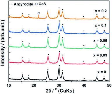 | ||
| Fig. 1 X-ray diffraction patterns of (1 − x)Li6PS5Cl–xCaS (0 ≤ x ≤ 0.2) synthesized by ball milling method. | ||
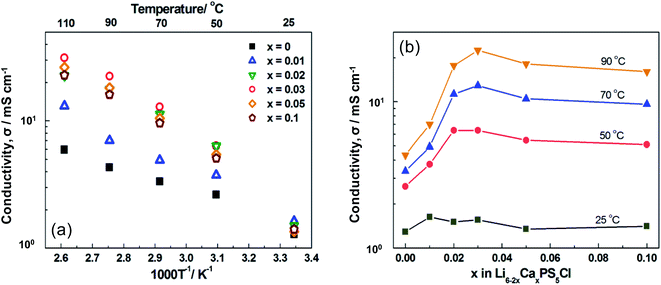
The relationship between temperature and ionic conductivity of the (1 − x)Li6PS5Cl–xCaS (0 ≤ x ≤ 0.2) doped samples was based on conductivity values calculated from the impedance plots (Fig. 2a). The impedance plots were also illustrated in Fig. S1.† These curves were characteristic of pure ionic conductors and included a spike attributed to the bulk, grain boundary, and electrode resistances of the solid electrolytes. The resistance values corresponded to the intercept of the Nyquist plot on the x-axis (e.g., when the imaginary part of the impedance is equal to zero). The ionic conductivity was calculated as the sum of the grain-boundary and bulk resistances. The ionic conductivity of the pure Li6PS5Cl solid electrolyte was 1.3 mS cm−1 at 25 °C, which was similar to a reported values of 1.33 mS cm−1.33 Meanwhile, the activation energy of 0.17 eV was lower than the previous reports of 0.30 eV.33 The ionic conductivity of Ca2+ doped Li6PS5Cl at room temperature (26 °C), where the x = 0.01, 0.02, 0.03, 0.05, and 0.1 samples, were slightly higher of 1.6, 1.5, 1.6, 1.4, and 1.4 mS cm−1, respectively. These results did not correspond with the findings a study on Li5.4Al0.2PS5Br solid electrolytes synthesized by mechanical milling methods with heat treatment.20 The Ca2+ doped Li6PS5Cl samples in which x = 0.01, 0.02, 0.03, 0.05, and 0.1 exhibited higher ionic conductivity than the undoped sample above 50 °C. Notably, the ionic conductivity of x = 0.02 was drastically improved. The x = 0.03 sample exhibited the highest ionic conductivity of 12.9 mS cm−1 at 70 °C, which was four times the conductivity of Li6PS5Cl (3.4 mS cm−1). The activation energy was calculated above 50 °C because the ionic conductivity at room temperature was relatively low along with the low linearity of the fitted curves. The activation energy slightly increased in the Ca2+ doped Li6PS5Cl compared with the pure Li6PS5Cl solid electrolyte, where the x = 0.01, 0.02, 0.03, 0.05, and 0.1 samples were 0.21, 0.23, 0.28, 0.28, and 0.27 eV, respectively. These activation energies for Ca-doped Li6PS5Cl (0.17–0.28 eV) were similar to other superionic conductors (typically, 0.2–0.3 eV).7–11
The ionic conductivity of the pure and (1 − x)Li6PS5Cl–xCaS doped samples was plotted as a function of x at different temperatures (Fig. 2b). All of the samples doped with Ca2+ had a higher ionic conductivity than pure Li6PS5Cl. The samples with x = 0.02 or 0.03 exhibited the highest ionic conductivity above 50 °C and these doping levels were explored further in multivalent cation doping.
Cation doping type
The XRD patterns of the (1 − x)Li6PS5Cl–xMX (where x = 0.02 or 0.03 and MX = BaS, SrS, YCl3, AlCl3, or ZnCl2) doped samples are given in Fig. 3. The characteristic peaks attributed to the argyrodite-type phase were observed in the patterns of all samples, confirming that the argyrodite-type Li6PS5Cl structure was maintained despite the introduction of various alkaline-earth-metal elements. Li2S was confirmed at both of the doping levels based on the diffraction peak at 2θ ≈ 27° assigned by Li2S (ICSD #196932). Although the ionic radii of Sr2+ (1.18 Å), Ba2+ (1.35 Å), Al3+ (0.39 Å), Zn2+ (0.64 Å), and Y3+ (0.90 Å) differ from Li+ (0.59 Å), no peak shifts of were observed in the BaS, SrS, YCl3, AlCl3, or ZnCl2 doped samples, as was previously observed in the Ca2+ samples (1.00 Å).32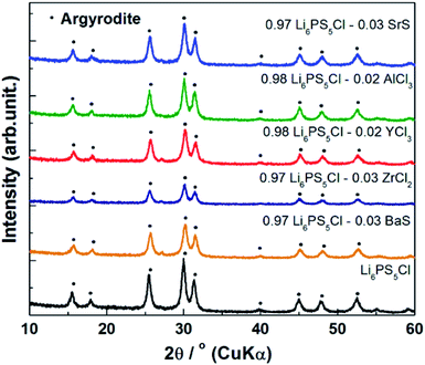 | ||
| Fig. 3 X-ray diffraction patterns of (1 − x)Li6PS5Cl–xMX (x = 0.02 or 0.03, MX = BaS, SrS, YCl3, AlCl3, ZnCl2) synthesized by ball milling method. | ||
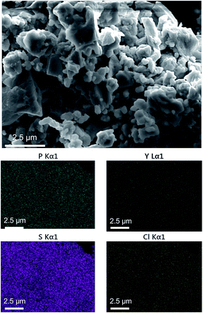
The SEM images of the 0.98Li6PS5Cl–0.02YCl3 solid electrolytes revealed particle sizes ranging from ca. 500 nm to 2 μm (Fig. 4). The distribution of Y3+ was investigated using EDS mapping images (Fig. 4), which indicated that Y3+ was well-dispersed compared with sulfur in the same regions. The SEM-EDS images of the 0.98Li6PS5Cl–0.02AlCl3 solid electrolytes are given in Fig. S2† and exhibit similar sizes, morphologies, and Al distribution. These results indicated that the other cation-doped Li6PS5Cl would have similar particle sizes, morphologies, and distribution of doping elements.
The temperature and ionic conductivity plots of the (1 − x)Li6PS5Cl–xMX doped samples indicated that the ionic conductivity of the Mg2+, Sr2+, and Ba2+ doped Li6PS5Cl was slightly higher at room temperature (Fig. 5). This difference became more substantial above 50 °C. The Sr2+, Ba2+ Al3+, and Zr2+ doped Li6PS5Cl exhibited slightly different behavior to the Ca2+ doped sample, where the Y3+ doped Li6PS5Cl consistently exhibited the highest ionic conductivity with values of 13, 22, 33, and 44 mS cm−1 at 50, 70, 90, and 110 °C, respectively. The ionic conductivity at 50 °C of the 0.98Li6PS5Cl–0.02YCl3 (13 mS cm−1) is higher than Li3PS4 (approximately 0.5 mS cm−1 at 50 °C),34 Li7P3S11 (approximately 10 mS cm−1 at 50 °C),7 Li6PS5Cl (approximately 2.6 mS cm−1 at 50 °C),33 and Li7P2S8I (approximately 2.0 mS cm−1 at 50 °C),35 although it was lower than LGPS of approximately 30 mS cm−1 at 50 °C.9 Thus, the 0.98Li6PS5Cl–0.02YCl3 has a significant advantage compared to these the state-of-the-art solid electrolytes in terms of the ionic conductivity.
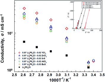 | ||
| Fig. 5 Temperature dependence of ionic conductivity of (1 − x)Li6PS5Cl–xMX (x = 0.02 or 0.03, MX = BaS, SrS, YCl3, AlCl3, ZnCl2). | ||
The activation energy slightly increased in the Y3+ doped Li6PS5Cl compared with the pure Li6PS5Cl solid electrolyte, which was 0.21 eV. This change exhibited a similar tendency to the Ca2+ doped Li6PS5Cl, which was also similar to other superionic conductors.
The impedance spectroscopies at room temperature and 50 °C of 0.98Li6PS5Cl–0.02YCl3 and Li6PS5Cl were illustrated in Fig. 5 for a direct comparison. The resistance value of the pure Li6PS5Cl solid electrolyte was 68 Ω and 34 Ω at room temperature and 50 °C, respectively. Meanwhile, the resistance value of 0.98Li6PS5Cl–0.02YCl3 significantly decreased to 21.7 Ω at 50 °C from 120 Ω at room temperature, although the absolute value depends on the sample thickness. These results also confirmed that the 0.98Li6PS5Cl–0.02YCl3 was more substantially improved than the pure Li6PS5Cl solid electrolyte between room temperature and 50 °C.
Improvement of ionic conductivity
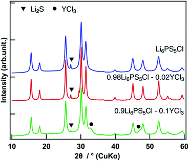
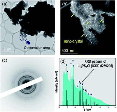
The synchrotron XRD pattern of the 0.98Li6PS5Cl–0.02YCl3 doped sample was evaluated, where the wavelength 1.541 Å was converted from 0.6199 Å in the raw data (Fig. 6). No peak shifts were observed. The Li2S starting material was observed in all doped samples and the peak intensities of Li2S were slightly different in the pure Li6PS5Cl, 0.98Li6PS5Cl–0.02YCl3, and 0.9Li6PS5Cl–0.1YCl3 samples. The 0.9Li6PS5Cl–0.1YCl3 sample exhibited diffraction peaks at 2θ ≈ 33°and 47°, which confirmed the presence of YCl3 based on the reference synchrotron XRD patterns of YCl3 (ICSD #15684). The slight variations in the amount of Li2S starting material between the pure Li6PS5Cl and 0.98Li6PS5Cl–0.02YCl3 samples had no effect on the ionic conductivity. The XRD pattern provides an indication of the average structure of the sample, thus slight changes in the local structure were not detected by XRD. Therefore, TEM was conducted to inspect the local structural changes at a nano-scale. The TEM image, HCDF image, and selected area electron diffraction patterns of the 0.98Li6PS5Cl–0.02YCl3 sample were evaluated (Fig. 7). The HCDF images revealed precipitated nanocrystals with a particle size ranging from ca. 10 to 30 nm randomly distributed throughout the sample. Considering the earlier SEM observations (Fig. 3) and previous reports on TEM observation at an atomic level, each multivalent cation doped Li6PS5Cl particle was expected to include several nanocrystals with domain boundaries.36 The TEM observation of the 0.9Li6PS5Cl–0.1YCl3 sample revealed that the size and distribution of the nanocrystals were similar to the 0.98Li6PS5Cl–0.02YCl3 sample (Fig. S3†). The electron diffraction pattern of the 0.98Li6PS5Cl–0.02YCl3 sample was compared with the XRD intensity of Li6PS5Cl (ICSD #259205) and all peaks in the pattern were attributed to Li6PS5Cl (Fig. 7d). No peak shifts were observed in pure Li6PS5Cl (ICSD #259205), further indicating that the nanocrystals observed in the HCDF images were likely Li6PS5Cl. The TEM observations indicated that a solid solution was not formed.20 These findings indicated that the doping element remained at the grain boundary between the particles and/or the domain boundary among the nanocrystals, leading to reduced grain boundary resistance. Besides, the temperature dependence of ionic conductivity (Fig. 2a and 5) was changed above 50 °C at all doped samples compared to the undoped sample, which was different from the previous report.20 This phenomenon might be affected by doping element remained at the grain boundary. There are several previous reports on the effects of grain boundary. H. Yamada et al. reported that the grain boundary resistance of a solid electrolyte (Li1.3Al0.3Ti1.7(PO4)3) was suppressed by coating a poorly conducting solid electrolyte (Li2SiO3).37 H. Xu et al. also reported on Li3OCl solid electrolytes in which the reduction of the grain boundary significantly influenced total ionic conductivity through an amorphous route.38 However, there was no direct evidence of the doping element at the grain boundary, nor of a change in grain boundary resistance, thus further analysis will be performed.Conclusion
This study explored the modification of grain boundaries for improved overall ionic conductivity of Li6PS5Cl solid electrolytes. Multivalent cation doped Li6PS5Cl was directly synthesized via mechanical milling synthesis with no heat treatment. The addition of a multivalent cation drastically improved ionic conductivity at higher temperatures (above 50 °C), where the 0.98Li6PS5Cl–0.02YCl3 sample exhibited an ionic conductivity five times higher (13 mS cm−1) than Li6PS5Cl (2.6 mS cm−1). However, the difference in ionic conductivity at room temperature was slight. The XRD pattern of the 0.98Li6PS5Cl–0.02YCl3 sample exhibited no shifts, even when using synchrotron XRD. Nanocrystals with a particle size ranging from ca. 10 to 30 nm were observed using TEM and neither peak shifts nor new peaks were observed in the electron diffraction patterns of these nanocrystals. These synchrotron XRD measurements and TEM observations revealed that the doping element remained at the grain boundary to lower the grain boundary resistance. These results are expected to offer insight for the development of other lithium-ion conductors for use in all-solid-state batteries, especially when the potential of bulk conductivity of solid electrolytes is to be completely investigated.Conflicts of interest
There are no conflicts to declare.Acknowledgements
This study was financial supported by the SOLiD-EV project (JPNP18003) of the New Energy and Industrial Technology Development Organization (NEDO). We also thank Ms. Makiko Oshida and Mr Keisuke Shinoda for their help for FE-SEM and EDS measurements at the National Institute for Materials Science (NIMS) Battery Research Platform. The synchrotron radiation experiments were performed at the BL02B2 of SPring-8 facility by Prof. Toshiyuki Matsunaga and Prof. Kentaro Yamamoto at Kyoto University with the approval of the Japan Synchrotron Radiation Research Institute (JASRI) (Proposal No. 2019B1500).References
- J. B. Goodenough and P. Singh, Review—Solid Electrolytes in Rechargeable Electrochemical Cells, J. Electrochem. Soc., 2015, 162(14), A2387–A2392 CrossRef CAS.
- M. Ribes, B. Barrau and J. L. Souquet, Sulfide glasses : glass forming region, structure and ionic conduction of glasses in Na2S-XS2 (X = Si, Ge), Na2S-P2S5 and Li2S-GeS2 systems, J. Non-Cryst. Solids, 1980, 38–39, 271–276 CrossRef CAS.
- J. L. Souquet, E. Robinel, B. Barrau and M. Ribes, Glass formation and ionic conduction in the M2S-GeS2 (M = Li, Na, Ag) systems, Solid State Ionics, 1981, 3–4, 317–321 CrossRef CAS.
- M. Murayama, Synthesis of New Lithium Ionic Conductor Thio-LISICON—Lithium Silicon Sulfides System, J. Solid State Chem., 2002, 168(1), 140–148 CrossRef CAS.
- R. Kanno, T. Hata, Y. Kawamoto and M. Irie, Synthesis of a new lithium ionic conductor, thio-LISICON–lithium germanium sulfide system, Solid State Ionics, 2000, 130(1), 97–104 CrossRef CAS.
- R. Kanno and M. Murayama, Lithium Ionic Conductor Thio-LISICON: The Li2S-GeS2-P2S5 System, J. Electrochem. Soc., 2001, 148(7), A742–A746 CrossRef CAS.
- F. Mizuno, A. Hayashi, K. Tadanaga and M. Tatsumisago, New Lithium-Ion Conducting Crystal Obtained by Crystallization of the Li2S-P2S5 Glasses, Electrochem. Solid-State Lett., 2005, 8(11), A603 CrossRef CAS.
- H. Yamane, M. Shibata, Y. Shimane, T. Junke, Y. Seino, S. Adams, K. Minami, A. Hayashi and M. Tatsumisago, Crystal structure of a superionic conductor, Li7P3S11, Solid State Ionics, 2007, 178(15–18), 1163–1167 CrossRef CAS.
- N. Kamaya, K. Homma, Y. Yamakawa, M. Hirayama, R. Kanno, M. Yonemura, T. Kamiyama, Y. Kato, S. Hama, K. Kawamoto and A. Mitsui, A lithium superionic conductor, Nat. Mater., 2011, 10, 682 CrossRef CAS PubMed.
- Y. Kato, S. Hori, T. Saito, K. Suzuki, M. Hirayama, A. Mitsui, M. Yonemura, H. Iba and R. Kanno, High-power all-solid-state batteries using sulfide superionic conductors, Nat. Energy, 2016, 1(4), 16030 CrossRef CAS.
- M. A. Kraft, S. P. Culver, M. Calderon, F. Böcher, T. Krauskopf, A. Senyshyn, C. Dietrich, A. Zevalkink, J. Janek and W. G. Zeier, Influence of Lattice Polarizability on the Ionic Conductivity in the Lithium Superionic Argyrodites Li6PS5X (X = Cl, Br, I), J. Am. Chem. Soc., 2017, 139(31), 10909–10918 CrossRef CAS PubMed.
- R. Schlem, M. Ghidiu, S. P. Culver, A.-L. Hansen and W. G. Zeier, Changing the Static and Dynamic Lattice Effects for the Improvement of the Ionic Transport Properties within the Argyrodite Li6PS5–xSexI, ACS Appl. Energy Mater., 2020, 3(1), 9–18 CrossRef CAS.
- T. Bernges, S. P. Culver, N. Minafra, R. Koerver and W. G. Zeier, Competing Structural Influences in the Li Superionic Conducting Argyrodites Li6PS5–xSexBr (0 ≤ x ≤ 1) upon Se Substitution, Inorg. Chem., 2018, 57(21), 13920–13928 CrossRef CAS PubMed.
- M. Xuan, W. Xiao, H. Xu, Y. Shen, Z. Li, S. Zhang, Z. Wang and G. Shao, Ultrafast solid-state lithium ion conductor through alloying induced lattice softening of Li6PS5Cl, J. Mater. Chem. A, 2018, 6(39), 19231–19240 RSC.
- P. Adeli, J. D. Bazak, K. H. Park, I. Kochetkov, A. Huq, G. R. Goward and L. F. Nazar, Boosting Solid-State Diffusivity and Conductivity in Lithium Superionic Argyrodites by Halide Substitution, Angew. Chem., Int. Ed. Engl., 2019, 58(26), 8681–8686 CrossRef CAS PubMed.
- C. Yu, Y. Li, M. Willans, Y. Zhao, K. R. Adair, F. Zhao, W. Li, S. Deng, J. Liang, M. N. Banis, R. Li, H. Huang, L. Zhang, R. Yang, S. Lu, Y. Huang and X. Sun, Superionic conductivity in lithium argyrodite solid-state electrolyte by controlled Cl-doping, Nano Energy, 2020, 69, 104396 CrossRef CAS.
- S. Ohno, B. Helm, T. Fuchs, G. Dewald, M. A. Kraft, S. P. Culver, A. Senyshyn and W. G. Zeier, Further Evidence for Energy Landscape Flattening in the Superionic Argyrodites Li6+xP1–xMxS5I (M = Si, Ge, Sn), Chem. Mater., 2019, 31(13), 4936–4944 CrossRef CAS.
- M. A. Kraft, S. Ohno, T. Zinkevich, R. Koerver, S. P. Culver, T. Fuchs, A. Senyshyn, S. Indris, B. J. Morgan and W. G. Zeier, Inducing High Ionic Conductivity in the Lithium Superionic Argyrodites Li6+xP1–xGexS5I for All-Solid-State Batteries, J. Am. Chem. Soc., 2018, 140(47), 16330–16339 CrossRef CAS PubMed.
- F. Zhao, J. Liang, C. Yu, Q. Sun, X. Li, K. Adair, C. Wang, Y. Zhao, S. Zhang, W. Li, S. Deng, R. Li, Y. Huang, H. Huang, L. Zhang, S. Zhao, S. Lu and X. Sun, A Versatile Sn-Substituted Argyrodite Sulfide Electrolyte for All-Solid-State Li Metal Batteries, Adv. Energy Mater., 2020, 10(9), 1903422 CrossRef CAS.
- Z. Zhang, J. Zhang, H. Jia, L. Peng, T. An and J. Xie, Enhancing ionic conductivity of solid electrolyte by lithium substitution in halogenated Li-Argyrodite, J. Power Sources, 2020, 450 CAS.
- Y. Gao and C. Cramer, Mixed cation effects in glasses with three types of alkali ions, Solid State Ionics, 2005, 176(29), 2279–2284 CrossRef CAS.
- W. Wieczorek, Z. Florjanczyk and J. R. Stevens, Composite polyether based solid electrolytes, Electrochim. Acta, 1995, 40(13), 2251–2258 CrossRef CAS.
- J. Maier, Nanoionics: ion transport and electrochemical storage in confined systems, Nat. Mater., 2005, 4(11), 805–815 CrossRef CAS PubMed.
- C. R. Stoldt and I. Lisenker, Grain Boundary Engineering in Solid-State Ionic Conductors, ECS Meeting Abstracts, 2016 Search PubMed.
- Y. Lin, S. Fang, D. Su, K. S. Brinkman and F. Chen, Enhancing grain boundary ionic conductivity in mixed ionic-electronic conductors, Nat. Commun., 2015, 6, 6824 CrossRef CAS PubMed.
- E. Nishibori, M. Takata, K. Kato, M. Sakata, Y. Kubota, S. Aoyagi, Y. Kuroiwa, M. Yamakata and N. Ikeda, The large Debye–Scherrer camera installed at SPring-8 BL02B2 for charge density studies, Nucl. Instrum. Methods Phys. Res., Sect. A, 2001, 467–468, 1045–1048 CrossRef CAS.
- H. Tsukasaki, H. Morimoto and S. Mori, Ionic conductivity and thermal stability of Li2O-Li2S-P2S5 oxysulfide glass, Solid State Ionics, 2020, 347 Search PubMed.
- B. Yao, T. Sun, A. Warren, H. Heinrich, K. Barmak and K. R. Coffey, High contrast hollow-cone dark field transmission electron microscopy for nanocrystalline grain size quantification, Micron, 2010, 41(3), 177–182 CrossRef CAS PubMed.
- A. K. Kulovits, G. Facco and J. M. K. Wiezorek, Grain size determination in nano-scale polycrystalline aggregates by precession illumination-hollow cone dark field imaging in the transmission electron microscope, Mater. Charact., 2012, 63, 17–26 CrossRef CAS.
- J. L. Lábár, Electron diffraction based analysis of phase fractions and texture in nanocrystalline thin films, part I: Principles, Microsc. Microanal., 2008, 14(4), 287–295 CrossRef.
- J. L. Labar, Consistent indexing of a (set of) single crystal SAED pattern(s) with the ProcessDiffraction program, Ultramicroscopy, 2005, 103(3), 237–249 CrossRef CAS PubMed.
- R. D. Shannon, Revised effective ionic radii and systematic studies of interatomic distances in halides and chalcogenides, Acta Crystallogr., Sect. A: Cryst. Phys., Diffr., Theor. Gen. Crystallogr., 1976, 32(5), 751–767 CrossRef.
- S. Boulineau, M. Courty, J.-M. Tarascon and V. Viallet, Mechanochemical synthesis of Li-argyrodite Li6PS5X (X = Cl, Br, I) as sulfur-based solid electrolytes for all solid state batteries application, Solid State Ionics, 2012, 221, 1–5 CrossRef CAS.
- Z. Liu, W. Fu, E. A. Payzant, X. Yu, Z. Wu, N. J. Dudney, J. Kiggans, K. Hong, A. J. Rondinone and C. Liang, Anomalous High Ionic Conductivity of Nanoporous β-Li3PS4, J. Am. Chem. Soc., 2013, 135(3), 975–978 CrossRef CAS PubMed.
- S.-J. Choi, S.-H. Lee, Y.-C. Ha, J.-H. Yu, C.-H. Doh, Y. Lee, J.-W. Park, S.-M. Lee and H.-C. Shin, Synthesis and Electrochemical Characterization of a Glass-Ceramic Li7P2S8I Solid Electrolyte for All-Solid-State Li-Ion Batteries, J. Electrochem. Soc., 2018, 165(5), A957–A962 CrossRef CAS.
- Y. Sugawara, S. Taminato, T. Hirayama, M. Hirayama, R. Kanno, Y. Ukyo and Y. Ikuhara, Interfacial Atomic Structures of Single-Phase Li2MnO3 Thin Film with Superior Initial Charge-Discharge Behavior, J. Electrochem. Soc., 2018, 165(2), A55–A60 CrossRef CAS.
- H. Yamada, D. Tsunoe, S. Shiraishi and G. Isomichi, Reduced Grain Boundary Resistance by Surface Modification, J. Phys. Chem. C, 2015, 119(10), 5412–5419 CrossRef CAS.
- H. Xu, M. Xuan, W. Xiao, Y. Shen, Z. Li, Z. Wang, J. Hu and G. Shao, Lithium Ion Conductivity in Double Anti-perovskite Li6.5OS1.5I1.5: Alloying and Boundary Effects, ACS Appl. Energy Mater., 2019, 6288–6294 CrossRef CAS.
Footnote |
| † Electronic supplementary information (ESI) available. See DOI: 10.1039/d0ra02545c |
| This journal is © The Royal Society of Chemistry 2020 |


