
 Open Access Article
 This Open Access Article is licensed under a Creative Commons Attribution-Non Commercial 3.0 Unported Licence
Bench-scale demonstration of CO2 capture with an electrochemically driven proton concentration process
Mohammad Rahimi a,
Giulia Cataliniab,
Monica Puccinib and
T. Alan Hatton*a
a,
Giulia Cataliniab,
Monica Puccinib and
T. Alan Hatton*a
aDepartment of Chemical Engineering, Massachusetts Institute of Technology, Cambridge, MA 02139, USA. E-mail: tahatton@mit.edu
bDepartment of Civil and Industrial Engineering, University of Pisa, Largo Lucio Lazzarino 2, 561226 Pisa, Italy
First published on 29th April 2020
Abstract
A thorough experimental investigation of a bench-scale apparatus of the proton concentration process with two symmetrical MnO2 electrodes is presented, with the aim of continuous desorption of CO2 from a K2CO3 solution. The electrodes were fabricated through cathodic deposition, and their chemical states, morphology, and microstructural architecture were characterized with X-ray photoelectron spectroscopy (XPS) and scanning electron microscopy (SEM). Successful formation of MnO2 film was confirmed by XPS analysis, and the SEM images showed a uniform distribution of the film across the carbon substrate surface and along the strand, with an average thickness of ∼500 nm, thus making proton ion diffusion possible. Continuous and efficient desorption of CO2 from a K2CO3 solution was obtained when electrodeposited MnO2 electrodes were used in a flow-based proton concentration process. The amount of CO2 desorbed per area of the electrode was 12-fold higher than that of a similar system. The electrochemical nature of the proton concentration process offers substantial practical advantages for the future, especially if electricity can be sustainably produced from renewable sources.
1. Introduction
Global warming resulting from the emission of greenhouse gases, particularly carbon dioxide (CO2), has drawn increasing attention in recent years. The atmospheric CO2 concentration was close to 415 ppm in May 2019, higher than the preindustrial level of approximately 300 ppm.1,2 The state-of-the-art technology for CO2 capture from large point sources, such as power plant flue gases, is amine scrubbing, followed by a thermal stripping process to regenerate the amine.3 Despite substantial advances on many fronts, this process still faces technical challenges that have hindered its deployment on very large scales; these challenges include amine degradation at high temperatures, the high energy requirement for regeneration, and high operational costs.4–6 Therefore, an opportunity exists for the development of alternative energy-efficient and economically viable CO2 capture technologies.A fundamentally different approach based on electrochemical processes has been suggested for CO2 capture. Expertise in the field of electrochemistry has been used to design systems that can selectively capture CO2 through either an adsorption process or bonding with a redox active species in an electrochemical cell. Early efforts in using electrochemistry for CO2 capture used a molten carbonate fuel cell to remove CO2 from complex gas streams.7 This approach suffered from high overall energetics and impurities (primarily water) in the separated CO2 stream, which made it unsuitable for practical large-scale applications.6 Another approach used electrochemical reduction of organic redox compounds to generate nucleophiles that could bind to the electrophilic carbon center in CO2, resulting in selective capture of CO2 from a gas mixture. Subsequently, to regenerate the organic absorbent and release pure CO2, the absorbent was oxidized electrochemically.6,8,9 Although quinone-based nucleophiles have been widely studied,8–11 other organic compounds such as bipyridine12 and thiolates13 have also been investigated. Other electrochemical approaches have recently been emerged, including electrochemically mediated amine regeneration14–17 and membrane capacitive deionization.18,19 These systems offer potentially lower energy consumption for CO2 capture and have led to a growing interest in using electrochemical processes as a promising alternative separation technique.
Carbon dioxide can also be captured using electrochemically controlled pH swings as the primary driver. These approaches take advantage of the pH sensitivity of the thermodynamic equilibrium of CO2. An increase in pH at the cathode of an electrochemical cell drives capture of CO2 as either HCO3− or CO32−, while release occurs at the anode where acidic conditions are created, leading to regeneration of free CO2.6 Two different processes, a bipolar membrane electrodialysis (BPMED)20 and a redox-mediated pH swing,21 have previously been introduced to exploit this pH responsiveness of CO2 hydration for CO2 separation. In BPMED, a voltage is applied across an alternating stack of anion-exchange membranes and water-dissociating bipolar membranes to drive CO2 capture via OH− generation and CO2 release via H+ generation. A redox-mediated pH swing using quinones has also been investigated. In that approach, CO2 was captured in the form of HCO3− at a gas-breathing cathode, where reduction of quinone to hydroquinone consumes protons, resulting in an increase in local pH. Subsequently, electromigration drives bicarbonate across the cell to the anode. At the anode, hydroquinone oxidation results in release of protons and a local pH decrease, which drives production of CO2 from HCO3−. The desorbed CO2 exits from the gas-breathing anode.21
We have recently developed an electrochemically driven proton concentration process for CO2 release based on modulation of the proton concentration in an electrochemical cell by a proton intercalating MnO2 electrode.22 The process, described in Fig. 1, consists of an absorber analogous to those used in thermal scrubbing systems and a two-compartment symmetrical electrochemical cell with MnO2 electrodes. A solution of potassium carbonate (K2CO3) in which CO2 is absorbed as bicarbonate (HCO3−) and carbonate (CO32−) is used as the absorbent. After absorption of CO2 in the absorber, the stream with high CO2 loading is sent to the anode compartment of the electrochemical cell, where deintercalation of protons from a MnO2 anode (i.e., MnOOH(s) → MnO2(s) + H+ + e−) increases the proton concentration and therefore shifts the CO2 (aq)/HCO3− (aq)/CO32− (aq) equilibrium toward CO2 formation. The desorbed CO2 is separated from the solution using a flash tank located after the anode compartment. To regenerate the absorbent, the stream is then sent to the cathode compartment, where the proton concentration is decreased as a result of proton intercalation (i.e., MnO2(s) + H+ + e− → MnOOH(s)). The regenerated solution is returned to the absorber column for further absorption.
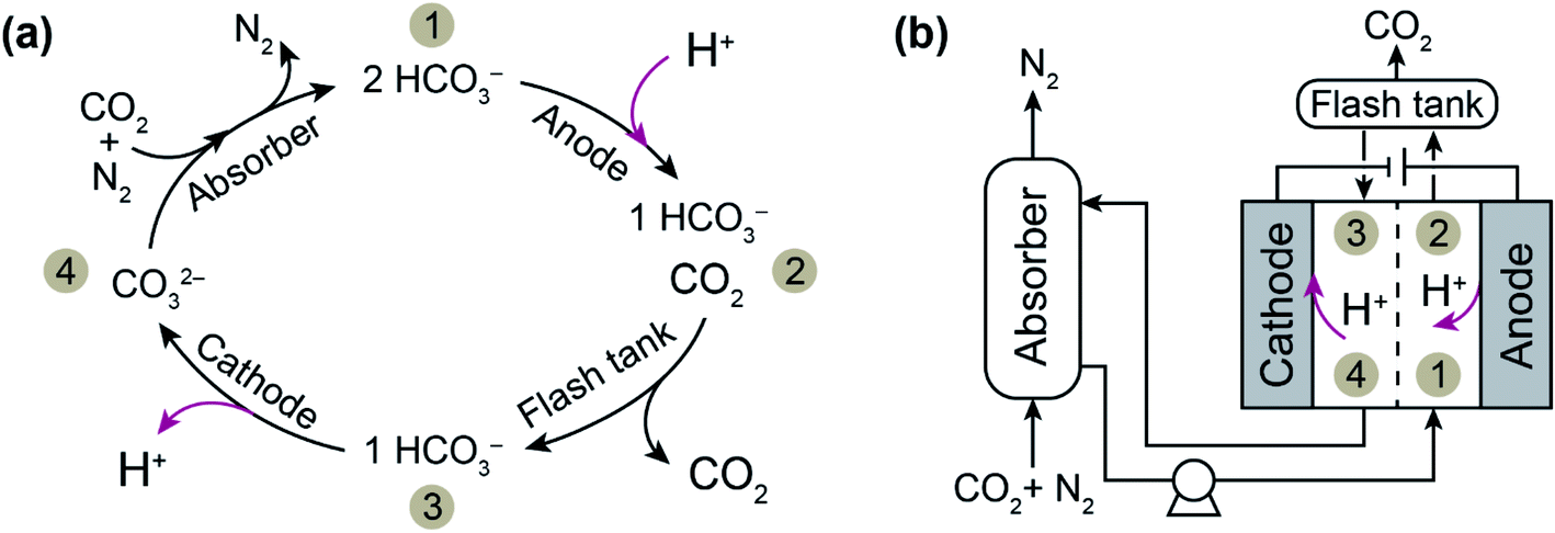 | ||
| Fig. 1 (a) The chemical (black arrows) and electrochemical (red arrows) reactions of CO2 capture with K2CO3 (denoted CO32−) as the absorbent and (b) a schematic diagram of the electrochemically driven proton concentration process. After the absorption stage, the stream is sent to the anode compartment of the electrochemical cell, where proton deintercalation from the electrode shifts the CO2 (aq)/HCO3− (aq)/CO32− (aq) equilibrium toward CO2 formation (i.e., 1 → 2), and this is followed by gas separation through a flash tank (i.e., 2 → 3). Subsequently, the absorbent is regenerated in the cathode compartment, where proton intercalation occurs (i.e., 3 → 4). | ||
The two common methods used to produce MnO2 electrodes are coprecipitation followed by casting onto a substrate23–26 and electrochemical deposition (electrodeposition) with an aqueous electrolyte containing a manganese precursor.27–30 Under different operating modes, the latter can be easily used to deposit a variety of morphologies of MnO2 with desired thicknesses.29 In addition, MnO2 electrodes produced by the electrodeposition method exhibit a high specific capacitance, a uniform distribution of the material on the substrate, and good cyclic stability.31,32 The MnO2 electrodes that we initially used for the proton concentration process were fabricated with the coprecipitation method followed by casting. This process could be further improved by using electrodeposition to prepare the electrodes.
Initial results from a proof-of-concept system demonstrated that the electrochemical work required for the proton concentration process to desorb CO2 captured from a flue gas stream is 33 kJe mol−1 CO2, thus suggesting that this process may be competitive with other electrochemical-based approaches (with energetics ranging from 31 to 49 kJe mol−1 CO2). In addition to the theoretical calculations, we demonstrated experimentally that MnO2 materials are good candidates for hosting proton ions during the oxidation–reduction (redox) reaction, enabling electrochemical modulation of the proton concentration through reversible cycles. Because the purpose of this experiment was to evaluate the proton intercalation/deintercalation rate and reversibility of MnO2 electrodes, the experiments were performed in a solution with a relatively low buffer capacity (i.e., KCl), in which the proton concentration changes could easily be seen as changes in the solution pH.
In this study, we present an experimental investigation of a bench-scale proton concentration modulation process with two symmetrical MnO2 electrodes to release the captured CO2 and regenerate the sorbent. In contrast to our previous proof-of-concept study in which we examined the electrodes in the absence of CO2, here we aimed to design a system that could continuously desorb CO2 from a K2CO3 solution. To do so, we initially developed an electrodeposition-based method to fabricate MnO2 electrodes with carbon cloth as the substrate. The fabricated electrodes were characterized to evaluate their chemical state as well as their morphological and capacitance properties. Finally, the fabricated electrodes were used in an electrochemical cell operated in a flow-based configuration to continuously desorb CO2. The kinetics of CO2 absorption by K2CO3 as the absorbent are relatively slow, but can be enhanced by the addition of rate promoters such as amino acids to the solution. It has been shown, for instance, that glycine, a common rate promoter added to K2CO3 solutions, accelerates the overall rate of absorption of CO2 by a factor of 22.33,34 Thus, we also considered using glycine as a rate promoter and studied its effect on the electrochemical performance of the system.
2. Materials and methods
2.1. Electrode fabrication
The electrodes were prepared through cathodic electrodeposition of MnO2 on carbon cloth (AvCarb Material Solutions) as the substrate, with a three-electrode cell (4 cm long and 3 cm in diameter) equipped with a Ag/AgCl (+0.211 V vs. SHE; RE-5B; BASi) reference electrode and a platinum counter electrode.35–37 The reference electrode was placed between the other two electrodes inserted on each side, and the electrolyte was mixed with a stirrer at 600 rpm. To uniformly distribute the potential over the electrode surface and collect the generated current, we inserted a piece of stainless steel (100 × 100 mesh; McMaster-Carr, OH) behind the electrode, attached with conductive carbon tape (Ted Pella Inc.). The cathodic electrodeposition was conducted with a solution of 0.02 M KMnO4 (Sigma-Aldrich) with or without (as discussed below) additional 0.1 M K2SO4 as the supporting electrolyte, and 0.01 M H2SO4 (Sigma-Aldrich) to acidify the solution.The electrodeposition was carried out under galvanostatic conditions with a current density of 1 mA cm−2 applied with a potentiostat (PARSTAT PMC-1000, Princeton Applied Research, USA) for 1 hour at room temperature. The effects of time and current density were further investigated by performing the electrodeposition at additional current densities of 1.5 and 2 mA cm−2 and deposition times of 2 and 3 hours. The quantity of deposited MnO2 was calculated according to mass changes of the electrodes, and the deposition coulombic efficiency was defined as the ratio between the amount of material deposited on the substrate and the expected value, on the basis of the charge transferred during the process.
MnO2 electrodes were also fabricated with a coprecipitation method followed by casting on a carbon substrate. Briefly, MnO2 powder was produced by coprecipitation of KMnO4 and MnSO4 precursors. The resulting MnO2 precipitate was mixed with a certain ratio of carbon black and polyvinylidene fluoride to form a composite. A solution of 1-methyl-2-pyrrolidinone was added to the composite, and the resulting slurry was cast onto carbon cloth substrate with a leveled glass plate. A detailed fabrication procedure based on this technique can be found in our previous report.22 This technique is denoted “casting” hereafter.
2.2. Electrode characterization
The electrodeposited electrodes were characterized with X-ray photoelectron spectroscopy (XPS) to evaluate their chemical states. The XPS analysis was performed on a Thermo Scientific K-Alpha+ XPS equipped with an Al (Kα) source with a spot size of 400 μm. The binding energies were calibrated with respect to the C 1s peak at 284.5 eV. High-resolution spectra were collected with a step size of 0.1 eV and an accumulation of ten scans. The film thickness and morphology, as well as the microstructural architecture of the deposited MnO2 materials on the carbon substrate, were observed through scanning electron microscopy (SEM) with a Zeiss Merlin high-resolution instrument.The capacitance properties of the fabricated MnO2 electrodes were investigated with the cyclic voltammetry (CV) technique. CV was performed in a three-electrode configuration with an Ag/AgCl reference electrode and a platinum wire as counter electrode. As the working electrode, a circular MnO2 electrode (3 mm in diameter) was attached to the glassy carbon electrode (3 mm in diameter; BASi) with conductive carbon tape. CVs were run over the potential range of 0.2 to 0.8 V with a scan rate of 1 or 2 mV s−1 and with 0.1 M K2SO4 as the electrolyte. In a separate set of experiments (data not shown here), we investigated the effect of scan rate on the pseudocapacitance behavior, especially on the material capacitance, and concluded that to evaluate the actual capacitance, it is necessary to run the CV tests at low scan rates (e.g., 1–5 mV s−1 as repeatedly reported in literature23,27,38). At higher scan rates there is less time for processes to equilibrate, thus only a small proportion of the material (primarily near the surface) can be accessed for charge storage, resulting in an underestimation of the material capacitance. As the scan rate decreases, the longer equilibration times allow more of the material to be utilized for charge storage via slower equilibrium processes, such as bulk charge storage.39 The capacitance was normalized by either the mass of active material (i.e., specific capacitance) or the geometrical surface of the electrode (i.e., geometrical capacitance). The normalized capacitance was calculated with a previously described procedure.40
The electrochemical characteristics of the electrodes were further investigated with proton intercalation experiments. A constant voltage of 1 V vs. Ag/AgCl was applied to the MnO2 electrode for 1 hour, and the generated current, which originated from the proton intercalation, as previously shown,22 was monitored. The amount of charge intercalated was calculated by integration of the generated current over time (i.e., 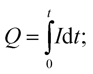 Q: charge intercalated (C), I: generated current (A), t: time (s)). The intercalation experiment was carried out with a three-electrode cell whose constituents were the same as those used in the electrodeposition process, except for the electrolyte solution, which was 0.5 M KHCO3 (Sigma-Aldrich) and 0.5 M KCl.
2.3. Flow cell configuration and operation
A flow-based electrochemical setup was developed to investigate the use of the fabricated MnO2 electrodes for the proton concentration process. The configuration used here was inspired by those used in flow batteries, in which electrolytes from two reservoir tanks are pumped into the chambers of an electrochemical cell and then back to the reservoir. The cell consisted of cathode and anode chambers, each 2 mm thick, separated by an anion-exchange membrane (Selemion AMV, Asashi Glass, Japan). The projected surface area of the electrode was 25.8 cm2 (4 in2), but plastic baffles were used to construct the flow path in the chamber; hence, the available surface area of the electrode was 17.5 cm2. Two identical MnO2 electrodes attached to stainless steel were used as the electrodes, which were placed at the end of each chamber. A peristaltic pump (Ismatec® Reglo Peristaltic Pumps) with four independent controllable channels with plastic tubes (Cole-Parmer PVC) with an internal diameter of 1/16 inch was used to circulate the anolyte and catholyte between the corresponding chambers and reservoir tanks. The solution pH of the anolyte, where CO2 is desorbed, was monitored at the exit of the anode with a pH probe (Orion™ PerpHecT™ ROSS™) calibrated before the experiment. Fig. 2 illustrates a schematic together with an image of the flow-based setup developed to study the proton concentration process.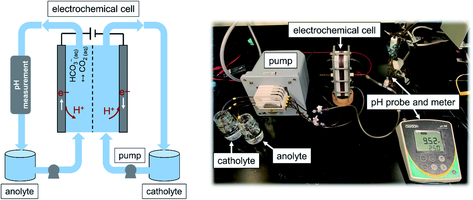 | ||
| Fig. 2 A schematic diagram (left panel) and image of the flow-based configuration (right panel) developed to study the proton concentration process. An electrochemical cell with two identical MnO2 electrodes with an effective projected area of 17.55 cm2 was used. The amount of CO2 desorbed was calculated by subtraction of the CO2 content of the anolyte at a given time from the initial content. The CO2 content was measured with a titration method. | ||
The experiment was carried out under a potentiostatic mode in which the cell was operated at a constant voltage (E) of 1 V, and the polarity was changed (i.e., E = −1 V) every 2 hours with a potentiostat. While the potential was applied, the generated current density (normalized to the geometrical area of the electrode) was recorded. Every one hour, the CO2 content of the anolyte was measured with a titration method that we previously developed.16 The amount of CO2 desorbed was calculated by subtraction of the CO2 content at a given time from the initial content. The experiment started with the same electrolyte for the anolyte and catholyte, containing 0.5 M K2CO3 absorbent and 0.5 M KCl as the supporting electrolyte. The electrolyte was saturated with 15 mol% CO2 mixed with 85 mol% N2 (Airgas, USA). As the experiment proceeded, the CO2 content of the anolyte was expected to decrease, whereas that in the catholyte was expected to remain the same.
3. Results and discussion
3.1. MnO2 electrode development
| MnO4− + e− → MnO42−, E0 = 0.56 V | (1) |
| MnO4− + 4H+ + 3e− → MnO2 + 2H2O, E0 = 0.60 V | (2) |
| MnO4− + 8H+ + 5e− → Mn2+ + 4H2O, E0 = 1.51 V | (3) |
These three reactions can be distinguished by their electrolyte acidity: reactions (2) and (3) are more favorable under acidic conditions. In addition, reduction reactions (1) and (2) (i.e., E0, presented versus a standard hydrogen electrode) require lower potentials than that needed for reaction (3). Therefore, to tune the selectivity of the MnO4− reduction through reaction (2) over the other two reactions, a MnO4− solution together with K2SO4 as the supporting electrolyte was used to increase the conductivity, hence decreasing the potential required for the deposition, and additional H2SO4 to reduce the pH was considered. The effects of adding a supporting electrolyte and additional acid on the solution conductivity, deposition overpotential, and capacitive behavior are shown in Fig. 3. The conductivity values showed a significant improvement when the supporting electrolyte was added to the MnO4− solution (2.6 mS cm−1 for MnO4− and 17.0 mS cm−1 for MnO4− + K2SO4; Fig. 3a). This finding was consistent with a lower overpotential being required for the electrodeposition when the supporting electrolyte was used (Fig. 3b). When additional H2SO4 was used to decrease the electrolyte pH, the conductivity slightly improved to 19.5 mS cm−1, mainly because of the additional ions introduced. The deposition overpotential significantly decreased from 0.73 V (for MnO4− + K2SO4) to 0.11 V when the electrolyte was further acidified, possibly because of improved kinetics of the electrodeposition reaction at lower pH values, similarly to that previously reported.42
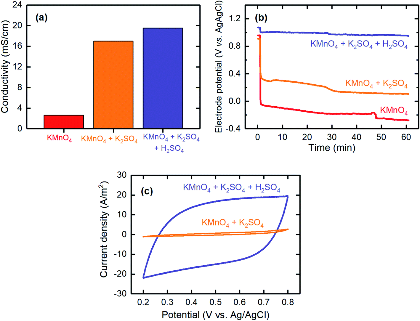 | ||
| Fig. 3 The effects of adding K2SO4 as the supporting electrolyte and acidifying the electrolyte with H2SO4 on the (a) conductivity, (b) electrode potential profile, and (c) CV of the electrodeposited electrodes prepared by cathodic deposition. The electrodes were electrodeposited galvanostatically with a current density of 1 mA cm−2 for 1 hour. The CV tests were conducted in a potential range between 0.2 and 0.8 V (vs. Ag/AgCl) at a scan rate of 1 mV s−1 and with 0.1 M Na2SO4 as the electrolyte. | ||
CV was used to evaluate the capacitive behavior of the electrodeposited electrodes. The CV results for the electrode fabricated with the acidified KMnO4 solution with K2SO4 supporting electrolyte showed a fairly rectangular shape, thereby confirming the pseudocapacitance behavior of the electrodes and indicating that these electrodes are a good candidate for proton intercalation/deintercalation reactions. However, the electrode fabricated in the absence of acid resulted in significantly lower current densities during the CV measurement, thus suggesting that it had a poor pseudocapacitance behavior (Fig. 3c). Therefore, it was necessary to acidify the electrolyte to improve the pseudocapacitance behavior of the electrodeposited electrodes.
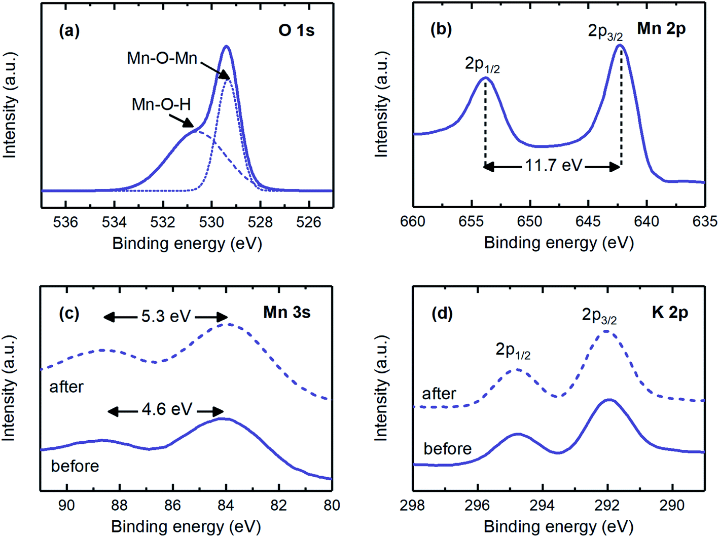 | ||
| Fig. 4 (a) O 1s, (b) Mn 2p, (c) Mn 3s, and (d) K 2p XPS spectra for the electrodeposited MnO2 electrodes. The dashed line, labeled “after”, in the Mn 3s and K 2p spectra corresponds to the electrode after reduction at 1 V for 1 hour. | ||
The main electrochemical reaction involved when MnO2 electrodes were polarized was studied by investigating the Mn 3s and K 2p spectra. The Mn 3s spectrum was evaluated to study the redox reaction, as the peak separation is an indication of the oxidation state of manganese. A peak separation of 4.6 eV was in agreement with that expected for the manganese oxidation state of +4 (i.e., Mn4+), whereas after the proton intercalation (i.e., reduction reaction) experiment, this separation increased to 5.3 eV, corresponding to the oxidation state of +3 (i.e., Mn3+; Fig. 4c).23 The K 2p spectrum was observed for the electrodeposited electrodes (Fig. 4d). The hypothetical reasons for these results may be that either some potassium ions were trapped during the MnO2 matrix formation as deposition progressed23 or these ions were involved in the matrix of the produced electrode, e.g., KxMnO2 (x ∼ 0.3).43,44 The former possibility is more likely, because the findings from the O 1s and Mn 2p spectra implied that the chemical states of the electrodeposited electrode were very similar to those of the coprecipitation method, in which pure MnO2 was produced. The peak energy separation, the location, and the intensity of the K 2p spectrum remained unchanged when the electrodes were reduced, thus suggesting that potassium intercalation was not significant. Given that the oxidation state of manganese changed from +4 to +3 during the reduction reaction, and potassium ions were not effectively involved in the redox reaction, we concluded that the main electrochemical reaction on the fabricated MnO2 electrodes was the proton-coupled reduction of MnO2 to MnOOH (i.e., MnO2(s) + H+ + e− → MnOOH(s)), thus making this electrode a good candidate for the proton concentration process, in which selective intercalation of protons is required.
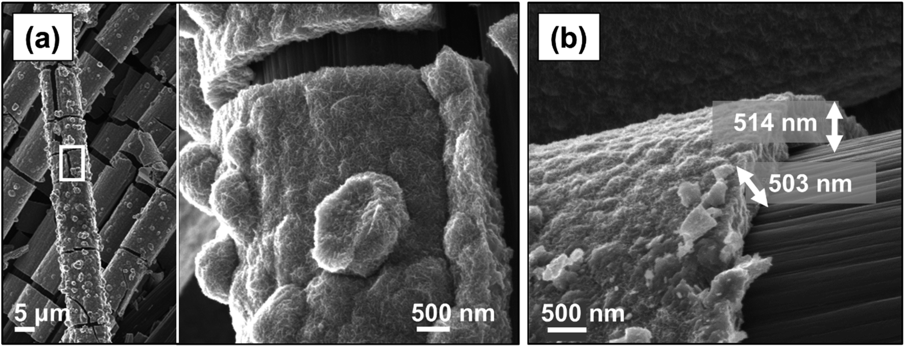
The morphological properties of the electrodeposited electrodes were investigated with SEM. As shown in Fig. 5a, MnO2 formed uniformly over the surface of the carbon cloth substrate without any observable particle agglomeration. The electrodeposited materials tended to cover the individual strands of the carbon cloth conformally (Fig. 5b), and their thickness ranged from 400 nm to 600 nm (Fig. 5c). Previous studies on the charge storage mechanism in MnO2 electrodes have indicated that only a thin layer, less than 500 nm, of this material is involved in the redox reaction;23 therefore, the thin MnO2 film produced here is effectively accessible for the proton intercalation process. Fig. 5d shows the corresponding high magnification SEM image indicating the formation of a nano-sized rosette-like structure with microporous architecture, similar to those previously observed.28,29,31 This structure provides a very high active surface area,45,46 which appears to be a promising feature for applications as electrodes, because such a microstructure would ensure maximum utilization of the MnO2 material within the diffusion length of the proton ions.
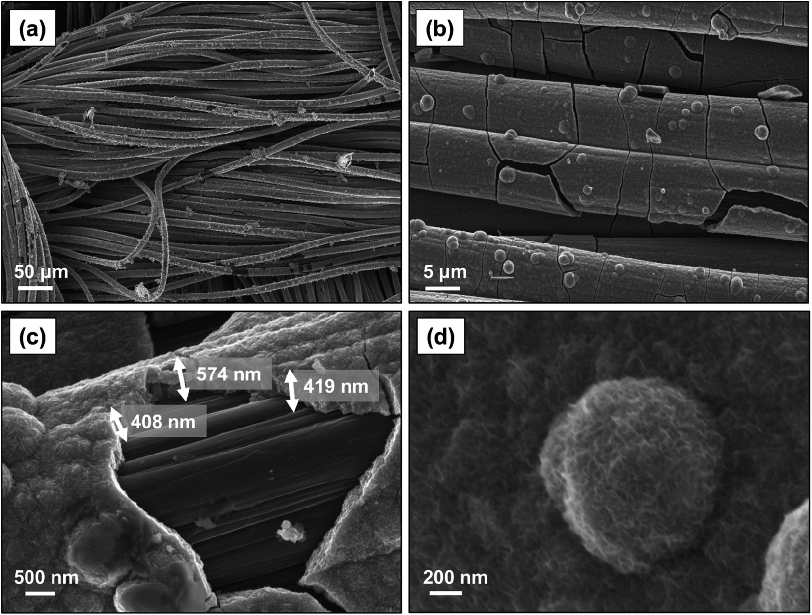 | ||
| Fig. 5 SEM images with various magnifications of MnO2 coated on carbon cloth substrate via cathodic electrodeposition at a current density of 1 mA cm−2 for 1 hour. | ||
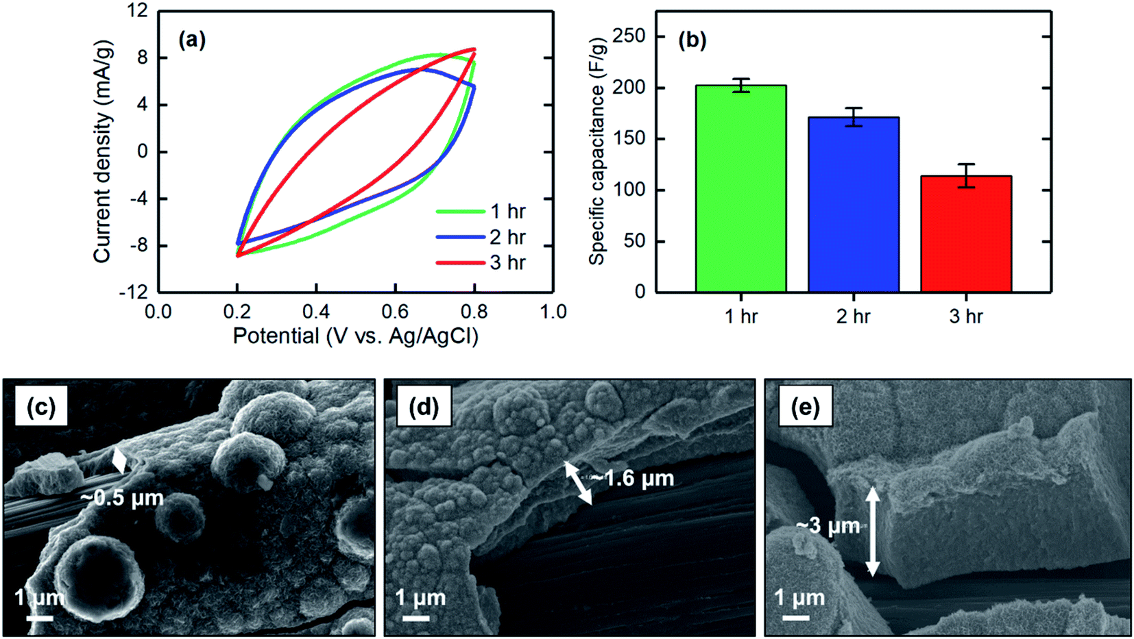 | ||
| Fig. 6 (a) CV at a scan rate of 2 mV s−1, (b) corresponding specific capacitance, and SEM images of the MnO2 electrodes electrodeposited at 1 mA cm−2 for (c) 1 hour, (d) 2 hours, and (e) 3 hours. | ||
The specific capacitances of electrodes electrodeposited at different current densities of 1, 1.5, and 2 mA cm−2 were measured. When the current density increased, the specific capacitance decreased, with values of 202 ± 7 F g−1 for 1 mA cm−2 to 81 ± 12 F g−1 for 2 mA cm−2 (Fig. 7a and b). This finding can be explained based on the low-magnification SEM images of the electrodeposited MnO2 coatings. As shown in Fig. 7c–e, the current density at which the electrodeposition was performed mainly affected the bulk properties of the materials formed on the carbon substrate. Electrodeposition at a current density of 1 mA cm−2 resulted in a uniform and smooth film along the carbon strands, whereas the film began to cleave when the current density increased to 1.5 mA cm−2. A further increase to 2 mA cm−2 resulted in formation of a grainy surface apparently lacking strong adhesion between the grains, thus making the deposited film physically unstable and likely less accessible for proton intercalation. Therefore, to obtain a uniform and stable film in which proton ions can be effectively intercalated, lower current densities are desirable.
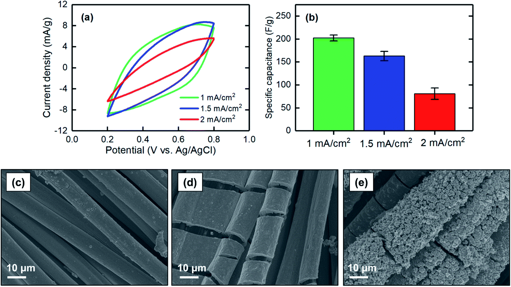 | ||
| Fig. 7 (a) CV at a scan rate of 2 mV s−1, (b) corresponding specific capacitance, and SEM images of the MnO2 electrodes electrodeposited at (c) 1 mA cm−2, (d) 1.5 mA cm−2, and (e) 2 mA cm−2 for 1 hour. | ||
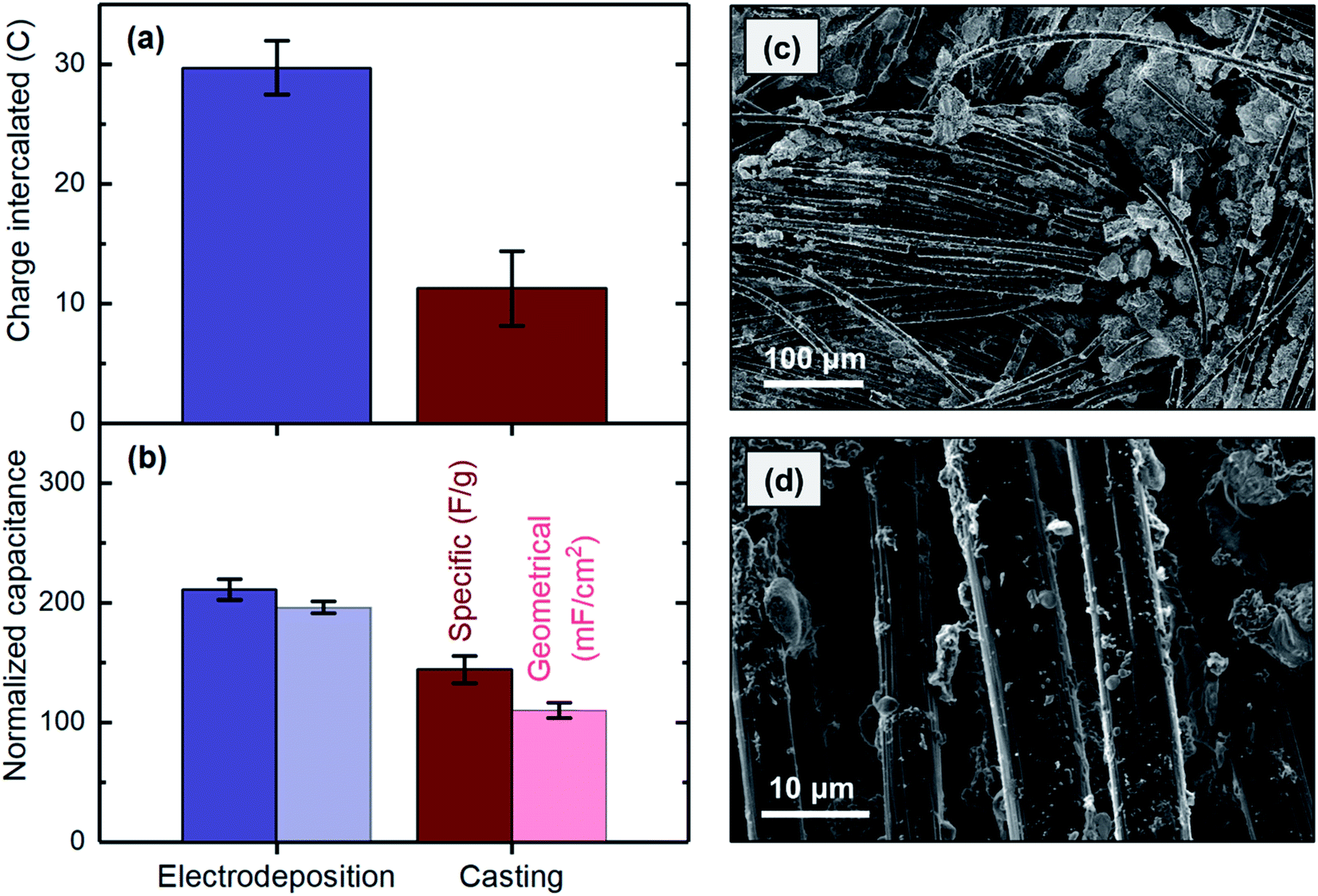 | ||
| Fig. 8 Comparing (a) charge intercalated and (b) capacitances of the electrodes fabricated with electrodeposition (blue) and casting (green) methods. (cand d) SEM images of an electrode prepared by casting. | ||
SEM analysis was used to study the distribution properties, e.g., uniformity, of MnO2 cast onto the carbon cloth substrate. Formation of MnO2 agglomerations between the carbon strands was clearly observed in several areas (Fig. 8c) but was not observed when the materials were uniformly electrodeposited on the surface (Fig. 5a). This finding is likely due to the difficulty in evenly distributing the materials on the substrate during the casting process, which usually involves drop casting or brushing a composite containing MnO2 on the substrate. In contrast, during the electrodeposition process, a uniform potential distribution developed along the substrate, thus resulting in a smooth and uniform film of MnO2. Lower layers of the agglomerations formed during the casting process might not be accessible as the thickness exceeds the diffusion length of proton ions. This possibility could explain the higher capacitance obtained for the electrodeposited electrode. In addition, individual carbon strands showed substantial bare spots with no MnO2 when the material was applied to the surface by casting (Fig. 8d), whereas the strands were fully covered after the electrodeposition (Fig. 5b). This finding originated from the differences in the nature of these two methods. During the casting process, accessing individual micrometer-thick strands is not feasible, because the material is applied to the bulk of the substrate. In electrodeposition, in contrast, the same electrical potential is developed along each strand in the substrate matrix, thus resulting in the strands becoming fully covered by MnO2. Therefore, to obtain MnO2 electrodes in which materials are uniformly distributed across the substrate surface and along the strand that can be effectively used for proton intercalation, the electrodes must be prepared by electrodeposition rather than by casting.
3.2. Continuous CO2 desorption
The electrodeposited MnO2 electrodes developed here were used in a flow-based proton concentration process to drive the release of CO2 from the solution. A constant potential of 1 V was applied, and the polarity was changed every 2 hours for four cycles. The results showed that the current generated was highly responsive to the potential, as when the polarity was changed, the current immediately responded. We experimentally demonstrated that CO2 can be effectively desorbed through the proton concentration process, as the experimental values of CO2 desorbed matched well with those expected on the basis of the current generation (Fig. 9). The expected CO2 desorption values were estimated based on the proton intercalation efficiency (i.e., moles of proton intercalated per mole of electron) of 0.7, as reported in previous investigations.23,47 A comparison of the experimental and expected values indicated that an average desorption efficiency of 81 ± 9% was achieved. The source of inefficiency might be due to the re-absorption of the desorbed gas by the electrolyte, as predicted in our previous investigation.16 During the desorption, CO2 loading (defined as CCO2/CCO2_initial) decreased and reached the final value of ∼0.6, indicating ∼80% desorption of the initially absorbed CO2 by the K2CO3 absorbent during the electrochemical process. It should be noted that a CO2 loading of 0.5 indicates 100% desorption, as half of the total initial CO2 was introduced by the K2CO3 absorbent.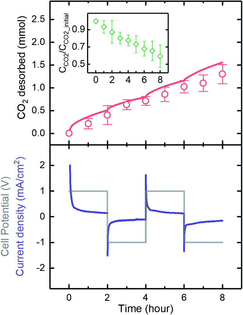 | ||
| Fig. 9 The current response (bottom panel), and the CO2 desorbed values (top panel; line: expected and red symbols: experimental) of a flow-based proton concentration process with two MnO2 electrodes. The inset graph on the top panel indicates the CO2 concentration at any time compared to that of the initial total CO2 concentration. A constant potential of 1 V was applied, and the polarity was changed every 2 hours for four cycles. | ||
The amount of CO2 desorbed in each cycle (∼0.4 mmol) was significantly higher than that released in a membrane capacitive deionization unit with three-fold larger electrodes (MCDI; ∼0.1 mmol),48 mainly because of the higher capacity of the electrodes used in the proton concentration process. The MnO2 electrode behaves as a pseudocapacitor with higher capacitance than offered by the pristine carbon electrodes used in MCDI, which rely only on the establishment of electrical double layers at the electrode surfaces to store charges. The CO2 capture rate with MCDI was estimated to be about 50 times lower than that of state-of-the-art adsorption materials such as zeolites,48,49 while the proton concentration process developed in this work yielded a significantly increased capacity, only 4 times lower than that of the state-of-the-art systems. Further growth of capacitive-based systems for CO2 capture to ensure that they are competitive with more established technologies will be spurred on by optimization of electrode properties and process configurations.
After the desorption experiment, i.e., 8 hours, the morphology and microstructure architecture of the electrodes were studied with SEM analysis. The results demonstrated that the nano-sized rosette-like structure of the MnO2 film was maintained, thus suggesting that the successive oxidation/reduction reactions on the electrode did not affect the morphology of the electrode coatings (Fig. 10a). In addition, the thickness of the MnO2 film on the carbon strand after the experiment (Fig. 10b; ∼500 μm) was comparable to that before the experiment (Fig. 5c). The electrode was weighed after the experiment and showed ∼5% loss of the material, owing to some parts of the film that were not physically very stable being washed away during the experiment. In this context, minor detachments of the film from the carbon strands were observed in the SEM images. This detachment could probably be avoided by using a binder (e.g., polyvinylidene fluoride) during the electrodeposition process.
 | ||
| Fig. 10 SEM images of the electrode used for the CO2 desorption experiment. | ||
We also investigated the effects of using a promoter on the performance of the proton concentration process. Because K2CO3 was used as the absorbent, and its kinetics of CO2 absorption are slow, using a promoter is essential for future development when the absorption stage is integrated into the electrochemical cell. Here, we performed investigations with glycine, which was previously shown to be an effective promoter,34,50,51 to understand the impact on cell performance. The CV results showed that glycine was electrochemically inactive, as no peaks were observed at the operational potential range of the proton concentration process (Fig. 11a). This inactivity is essential, because otherwise, reduction or oxidation of the promoter would decrease not only performance over time as a rate promoter but also coulombic efficiency, as the current generated would be consumed by this parasitic reaction rather than the proton intercalation/deintercalation process. In addition, we found that the promoter did not affect the current generated when the electrode was polarized to a negative (intercalation) or positive (deintercalation) potential, thus suggesting that it did not interfere with the electrochemical reactions (Fig. 11b). Therefore, glycine can be safely used as the promoter in future development of the proton concentration process.
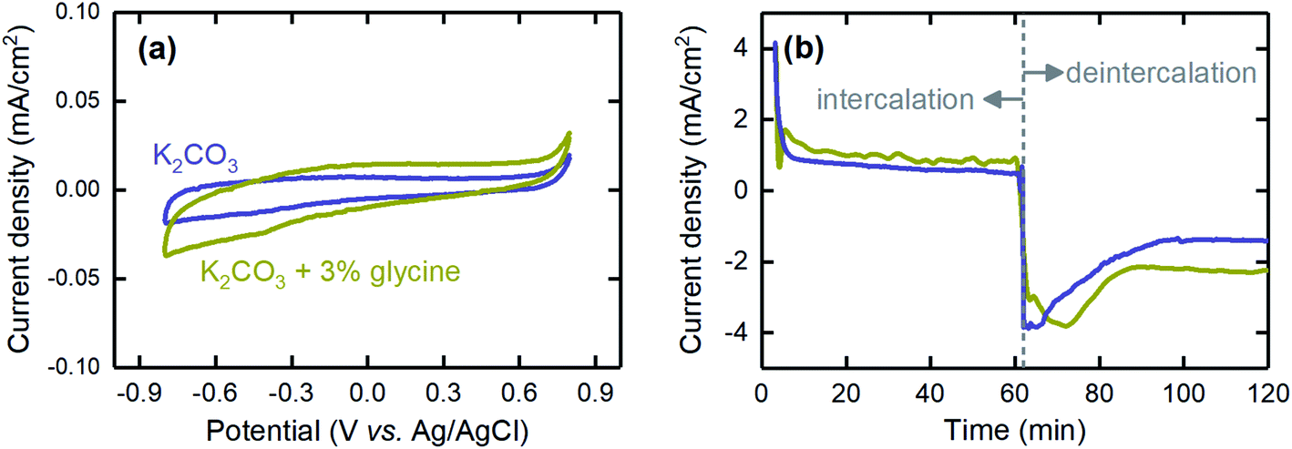 | ||
| Fig. 11 The effects of using glycine, as the absorption rate promoter, on (a) the CV profile and (b) the current generated when the electrode was polarized with a negative (intercalation) or positive (deintercalation) potential. The blue and olive lines represent K2CO3 absorbent with and without glycine, respectively. | ||
4. Conclusions
A bench-scale demonstration of CO2 capture and release due to proton release from appropriately polarized MnO2 electrodes has been demonstrated. The electrodes were fabricated through cathodic deposition from a solution of KMnO4 as the precursor. Our results indicated that it is essential to use K2SO4 as the supporting electrolyte and to acidify the solution with H2SO4 to efficiently obtain MnO2 during the electrodeposition process. The electrodeposited MnO2 materials were uniformly distributed across the substrate surface and along the strands of the carbon cloth, with an average thickness of ∼500 nm, a value within the critical diffusion length of proton ions. The electrodeposited electrodes resulted in a higher charge intercalation capacity as well as specific and geometrical capacitances, as compared with those of the electrodes fabricated through a coprecipitation and casting approach. By implementing the optimized electrodeposited MnO2 electrodes in a flow-based proton concentration process, we showed that CO2 can be continuously and efficiently desorbed from a K2CO3 solution saturated with 15 mol% CO2.The proton concentration process is in an early stage of development, and many aspects of the process could be further improved. Future developments could focus on building an integrated system in which the absorption stage is connected to the electrochemical cell, and CO2 could be absorbed and desorbed in one setup. In addition, other pseudocapacitors that potentially host protons together with new chemistries (e.g., absorbents, supporting electrolytes, or promoters) could be considered. Overall, the developed proton concentration process using an industrially relevant absorbent is an attractive electrochemical-based technology that could effectively capture CO2.
Conflicts of interest
There are no conflicts to declare.Acknowledgements
The authors would like to acknowledge Dr Katherine Phillips for conducting the XPS tests and Dr Miao Wang from the Department of Chemical Engineering at MIT for providing the electrochemical cell and for useful discussions. We also thank Dr David Calabro from ExxonMobil Research and Engineering Company for useful discussions. The research was supported financially by ExxonMobil.References
- C.-H. Yu, C.-H. Huang and C.-S. Tan, Aerosol Air Qual. Res., 2012, 12, 745–769 CrossRef CAS.
- K. Hashimoto, in Global Carbon Dioxide Recycling, Springer, 2019, pp. 5–17 Search PubMed.
- G. T. Rochelle, Science, 2009, 325, 1652–1654 CrossRef CAS PubMed.
- T. N. G. Borhani, A. Azarpour, V. Akbari, S. R. W. Alwi and Z. A. Manan, Int. J. Greenhouse Gas Control, 2015, 41, 142–162 CrossRef CAS.
- M. Bui, C. S. Adjiman, A. Bardow, E. J. Anthony, A. Boston, S. Brown, P. S. Fennell, S. Fuss, A. Galindo and L. A. Hackett, Energy Environ. Sci., 2018, 11, 1062–1176 RSC.
- J. H. Rheinhardt, P. Singh, P. Tarakeshwar and D. A. Buttry, ACS Energy Lett., 2017, 2, 454–461 CrossRef CAS.
- R. Huebscher and A. D. Babinsky, SAE Trans., 1969, 78, 2164–2170 Search PubMed.
- B. Gurkan, F. Simeon and T. A. Hatton, ACS Sustainable Chem. Eng., 2015, 3, 1394–1405 CrossRef CAS.
- S. Voskian and T. A. Hatton, Energy Environ. Sci., 2019, 12, 3530–3547 RSC.
- P. Scovazzo, J. Poshusta, D. DuBois, C. Koval and R. Noble, J. Electrochem. Soc., 2003, 150, D91–D98 CrossRef CAS.
- D. H. Apaydin, E. D. Głowacki, E. Portenkirchner and N. S. Sariciftci, Angew. Chem., Int. Ed., 2014, 53, 6819–6822 CrossRef CAS PubMed.
- R. Ranjan, J. Olson, P. Singh, E. D. Lorance, D. A. Buttry and I. R. Gould, J. Phys. Chem. Lett., 2015, 6, 4943–4946 CrossRef CAS PubMed.
- P. Singh, J. H. Rheinhardt, J. Z. Olson, P. Tarakeshwar, V. Mujica and D. A. Buttry, J. Am. Chem. Soc., 2017, 139, 1033–1036 CrossRef CAS PubMed.
- M. C. Stern, F. Simeon, H. Herzog and T. A. Hatton, Energy Environ. Sci., 2013, 6, 2505–2517 RSC.
- M. C. Stern and T. A. Hatton, RSC Adv., 2014, 4, 5906–5914 RSC.
- M. Wang, S. Hariharan, R. A. Shaw and T. A. Hatton, Int. J. Greenhouse Gas Control, 2019, 82, 48–58 CrossRef CAS.
- M. Wang, M. Rahimi, A. Kumar, S. Hariharan, W. Choi and T. A. Hatton, Appl. Energy, 2019, 255, 113879 CrossRef CAS.
- L. Legrand, O. Schaetzle, R. De Kler and H. Hamelers, Environ. Sci. Technol., 2018, 52, 9478–9485 CrossRef CAS PubMed.
- L. Legrand, Q. Shu, M. Tedesco, J. Dykstra and H. Hamelers, J. Colloid Interface Sci., 2020, 564, 478–490 CrossRef CAS PubMed.
- M. D. Eisaman, L. Alvarado, D. Larner, P. Wang, B. Garg and K. A. Littau, Energy Environ. Sci., 2011, 4, 1319–1328 RSC.
- J. D. Watkins, N. S. Siefert, X. Zhou, C. R. Myers, J. R. Kitchin, D. P. Hopkinson and H. B. Nulwala, Energy Fuels, 2015, 29, 7508–7515 CrossRef CAS.
- M. Rahimi, G. Catalini, S. Hariharan, M. Wang, M. Puccini and T. A. Hatton, Cell Reports Physical Science, 2020, 1, 100033 CrossRef.
- M. Toupin, T. Brousse and D. Bélanger, Chem. Mater., 2004, 16, 3184–3190 CrossRef CAS.
- J. Li, X. Wang, Q. Huang, S. Gamboa and P. Sebastian, J. Power Sources, 2006, 160, 1501–1505 CrossRef CAS.
- B. Zhao, M. Lu, Z. Wang, Z. Jiao, P. Hu, Q. Gao, Y. Jiang and L. Cheng, J. Alloys Compd., 2016, 663, 180–186 CrossRef CAS.
- T. E. Kibona, G. N. Shao, H. T. Kim and C. K. King'ondu, Nano-Struct. Nano-Objects, 2019, 17, 21–33 CrossRef CAS.
- P. Simon and Y. Gogotsi, in Nanoscience And Technology: A Collection of Reviews from Nature Journals, World Scientific, 2010, pp. 320–329 Search PubMed.
- P. Walker, M. Mauter and J. Whitacre, Electrochim. Acta, 2015, 182, 1008–1018 CrossRef CAS.
- I.-T. Kim, N. Kouda, N. Yoshimoto and M. Morita, J. Power Sources, 2015, 298, 123–129 CrossRef CAS.
- A. Kovalyk, O. Tananaiko, A. Borets, M. Etienne and A. Walcarius, Electrochim. Acta, 2019, 306, 680–687 CrossRef CAS.
- Y.-C. Chen, Y.-K. Hsu, Y.-G. Lin, Y.-K. Lin, Y.-Y. Horng, L.-C. Chen and K.-H. Chen, Electrochim. Acta, 2011, 56, 7124–7130 CrossRef CAS.
- C.-C. Hu, C.-Y. Hung, K.-H. Chang and Y.-L. Yang, J. Power Sources, 2011, 196, 847–850 CrossRef CAS.
- S. Park, H.-J. Song, M.-G. Lee and J. Park, Korean J. Chem. Eng., 2014, 31, 125–131 CrossRef CAS.
- H. Thee, N. J. Nicholas, K. H. Smith, G. da Silva, S. E. Kentish and G. W. Stevens, Int. J. Greenhouse Gas Control, 2014, 20, 212–222 CrossRef CAS.
- M. Rahimi, A. D'Angelo, C. A. Gorski, O. Scialdone and B. E. Logan, J. Power Sources, 2017, 351, 45–50 CrossRef CAS.
- M. Rahimi, T. Kim, C. A. Gorski and B. E. Logan, J. Power Sources, 2018, 373, 95–102 CrossRef CAS.
- X. Zhu, T. Kim, M. Rahimi, C. A. Gorski and B. E. Logan, ChemSusChem, 2017, 10, 797–803 CrossRef CAS PubMed.
- M. V. K. Azhagan, M. V. Vaishampayan and M. V. Shelke, J. Mater. Chem. A, 2014, 2, 2152–2159 RSC.
- M. F. Dupont and S. W. Donne, J. Power Sources, 2016, 326, 613–623 CrossRef CAS.
- W. Shi, X. Zhou, J. Li, E. R. Meshot, A. D. Taylor, S. Hu, J.-H. Kim, M. Elimelech and D. L. Plata, Environ. Sci. Technol. Lett., 2018, 5, 692–700 CrossRef CAS.
- P. Atkins, Physical Chemistry, W.H. Freeman and Company, New York, 1997 Search PubMed.
- C. Castledine and B. Conway, J. Appl. Electrochem., 1995, 25, 707–715 CrossRef.
- R. Chen and M. S. Whittingham, J. Electrochem. Soc., 1997, 144, L64–L67 CrossRef CAS.
- C. Vaalma, G. A. Giffin, D. Buchholz and S. Passerini, J. Electrochem. Soc., 2016, 163, A1295–A1299 CrossRef CAS.
- M. Mazloumi, M. Attarchi, A. Lak, M. S. Mohajerani, A. Kajbafvala, S. Zanganeh and S. Sadrnezhaad, Mater. Lett., 2008, 62, 4184–4186 CrossRef CAS.
- M. Feilizadeh, M. Rahimi, S. E. Zakeri, N. Mahinpey, M. Vossoughi and M. Qanbarzadeh, Can. J. Chem. Eng., 2017, 95, 1228–1235 CrossRef CAS.
- S.-L. Kuo and N.-L. Wu, J. Electrochem. Soc., 2006, 153, A1317–A1324 CrossRef CAS.
- L. Legrand, O. Schaetzle, R. de Kler and H. V. Hamelers, Environ. Sci. Technol., 2018, 52, 9478–9485 CrossRef CAS PubMed.
- J. Merel, M. Clausse and F. Meunier, Ind. Eng. Chem. Res., 2008, 47, 209–215 CrossRef CAS.
- Z. Zhang, Y. Li, W. Zhang, J. Wang, M. R. Soltanian and A. G. Olabi, Renewable Sustainable Energy Rev., 2018, 98, 179–188 CrossRef CAS.
- G. Hu, K. H. Smith, Y. Wu, S. E. Kentish and G. W. Stevens, Energy Fuels, 2017, 31, 4280–4286 CrossRef CAS.
| This journal is © The Royal Society of Chemistry 2020 |