
 Open Access Article
 This Open Access Article is licensed under a Creative Commons Attribution-Non Commercial 3.0 Unported Licence
Catalytic characteristics of a Ni–MgO/HZSM-5 catalyst for steam reforming of toluene
Wei Wua,
Qizhou Fan *ab,
Baojun Yi*ab,
Bichen Liua and
Rujiao Jianga
*ab,
Baojun Yi*ab,
Bichen Liua and
Rujiao Jianga
aCollege of Engine, Huazhong Agricultural University, No. 1, Shizishan Street, Hongshan District, Wuhan, 430070, PR China. E-mail: qizhoufan@mail.hzau.edu.cn; bjyi@mail.hzau.edu.cn; Fax: +86 27 87282120; Tel: +86 27 87282120
bKey Laboratory of Agricultural Equipment in the Mid-lower Yangtze River, Ministry of Agriculture and Rural Affairs, Wuhan, 430070, PR China
First published on 2nd June 2020
Abstract
Steam reforming is a potential technology for the conversion of biomass pyrolysis tar into gaseous products. In this study, HZSM-5 was selected as the nickel-based catalyst support and toluene was chosen as the tar model compound. Ni was replaced with MgO to improve the coking resistance of the catalyst. The effects of Ni and MgO loading on toluene conversion and gaseous product generation rate were investigated. The low Ni-loading Ni/HZSM-5 catalyst exhibited poor catalytic activity, whereas a high Ni-loading catalyst displayed poor coking resistance. The addition of the MgO promoter enhanced the steam reforming performance of the Ni/HZSM-5 catalyst with a low loading of active metal Ni (3 wt%). The optimal MgO loading was found at 6 wt%. By characterizing the catalyst before and after the reaction, we found that MgO would enter the wall and pores of the support, resulting in increased pore size and decreased specific surface area. Ni and MgO were combined to form NiO–MgO solid solution active centers, which enhanced the catalytic reforming performance. Moreover, more MgO loading increased the alkaline strength of the catalytic surface, enhanced the adsorption of CO2, and improved the resistance to carbon deposition. This study revealed the feasibility of replacing Ni with MgO and the potential mechanism of maintaining similar catalytic performance. This study also laid the theoretical foundation for the industrial application of nickel-based catalysts.
1. Introduction
Renewable energy has received increasing attention due to the depletion of fossil fuel energy and the deterioration of the environment.1 The use of biomass is a carbon-neutral process.2 Of all the biomass conversion processes, gasification is one of the most promising conversion processes.3 However, tar production is an inevitable problem during biomass gasification. Tar is produced by the condensation of monocyclic or polycyclic aromatic compounds, other oxygen-containing hydrocarbons and complex polycyclic aromatic hydrocarbons.4 Condensation of tar is prone to cause blockages in pipes or engines, reducing system efficiency and increasing maintenance costs.5 Therefore, the reduction or removal of biomass tar is crucial for biomass gasification.Steam reforming has been considered as a potential technology to convert tar into H2 and CO.6 A great deal of literature has reported that the metal loading catalysts have effect on biomass tar steam reforming.7 In particular, nickel-based catalysts have been widely used in biomass tar catalytic reforming owing to their high activity.8,9 As an important class of crystalline aluminosilicates, HZSM-5 have also been widely used as a support for Nickel-based catalyst due to the well-defined pore structures, extremely high surface area, and high surface acidity.10 HZSM-5 has been used as a support for steam reforming of Ni-based catalysts.11 Tang et al.12 investigated the performance of HF modified HZSM-5 supported nickel catalysts in steam reforming of toluene and biomass pyrolysis tar. And the results indicated that less acid sites is key to anti-coke property, 9%Ni/HF modified HZSM-5 exhibited a high carbon deposition resistance. It was reported that as a promoter, alkaline earth metal oxides could adjust the catalyst surface acidity to increase the catalyst surface activity.13 Ahmed et al.14 examined the steam reforming performance of Ni/zeolite, Ni–Fe/zeolite, and Ni–Fe–Mg/zeolite catalysts with toluene as tar model compound. The addition of Mg enabled Ni–Fe metal alloys to form more alkaline catalytic sites, thus enhancing tar reforming reactions.
In terms of catalytic performance and cost savings, nickel-based catalysts has significant advantages in tar catalytic reforming with Ni loading generally ranging from 1 to 20 wt%.15–17 Although, commercial reforming catalysts typically contained Ni loading of 20%, with some Ni loadings reaching 50%.18 However, more nickel loading tends to cause nickel accumulation, which made a lot of nickel ineffective and caused unnecessary waste.19 Meanwhile, the use of nickel-based catalysts was usually associated with problems during steam reforming process, in which the formation of coke on the catalyst surface results in catalyst deactivation.20 Generally, the adjustment of the active metal loading amount and the molar ratio of active metal/promoter could improve the steam reforming performance of the catalyst. For example, the increased Ni loading was reported to result in higher catalytic activity and stability.21 However, for Ni-based catalysts with promoters, stable peak catalytic activity was generally obtained by increasing the ratio of Ni/promoter. Chen et al.22 reported that a Ni–MgO/HZSM-5 catalyst with a Ni/MgO ratio of 3![[thin space (1/6-em)]](https://www.rsc.org/images/entities/char_2009.gif) :1 (Ni loading 6 wt%, MgO loading 2 wt%) exhibited the highest catalytic activity and the lowest coke deposition rate. Kazuya et al.23 revealed that Ni–MgO/Al2O3 catalyst with a Ni/MgO ratio of 6:1 (Ni loading 12 wt%, MgO loading 2 wt%) displayed the highest tar catalytic activity and stability. At present, modification of Ni-based catalysts by adding small amount of MgO to improve the catalytic performance of the catalysts has become a common practice.
:1 (Ni loading 6 wt%, MgO loading 2 wt%) exhibited the highest catalytic activity and the lowest coke deposition rate. Kazuya et al.23 revealed that Ni–MgO/Al2O3 catalyst with a Ni/MgO ratio of 6:1 (Ni loading 12 wt%, MgO loading 2 wt%) displayed the highest tar catalytic activity and stability. At present, modification of Ni-based catalysts by adding small amount of MgO to improve the catalytic performance of the catalysts has become a common practice.
In order to reduce costs and improve coking resistance of catalysts, replacing Ni with MgO. This study examined the effect of Ni, MgO loading on the conversion of toluene and the distribution of gaseous products by using HZSM-5 as the Ni-based support and toluene as a tar model compound. Then, the mechanism of catalyst Ni/HZSM-5 with MgO as a promoter was investigated by characterizing the catalyst before and after the reaction. This work lays a theoretical foundation for the industrial application of catalyst Ni–MgO/HZSM-5.
2. Materials and methods
2.1 Materials and catalyst preparation
The HZSM-5 catalyst (Si/Al = 50) purchased from the Catalyst Plant of Nankai University was used for the catalyst support. Nickel nitrate hexahydrate Ni(NO3)2·6H2O and crystalline powder of magnesium nitrate hexahydrate Mg(NO3)2·6H2O (analytical grade, Sinopharm Chemical Reagent Co., Ltd.) were used as Ni and MgO precursors. The Ni/HZSM-5 catalyst was prepared by the initial wet impregnation method. HZSM-5 was immersed in a certain amount of Ni (NO3)2·6H2O aqueous solutions with the loading of Ni of 3 wt%, 6 wt%, 9 wt%, respectively. The Ni–MgO/HZSM-5 catalyst was prepared by co-impregnation method. HZSM-5 was immersed in a certain amount of mixed aqueous solution of Ni (NO3)2·6H2O and Mg(NO3)2·6H2O with the loading of Ni of 3 wt%, the loading of MgO of 3 wt%, 6 wt%, and 9 wt%. Afterwards, the resultant aqueous solution was placed in a magnetic stirrer, and stirred at a constant temperature of 80 °C for evaporation, and then the sample was dried in an oven at 105 °C for 24 h. The dried catalyst was calcined at 600 °C for 3 hours in the air. The calcined catalyst was broke and sieved to a particle size of 100–200 μm. Prior to the activity test, these catalyst materials were reduced at 600 °C for 3 h in the H2.2.2 Catalytic activity test
The steam reforming reaction of toluene was carried out in a fixed bed tubular flow reactor, as shown in Fig. 1. The inside diameter of the quartz reactor was 20 mm. The two ends of the catalyst were supported by quartz wool, and 0.5 g of the catalyst was loaded into the center of the quartz reaction tube. The temperature of the reactor was controlled by a temperature controller, and the catalytic reaction temperature was 700 °C. N2 was used as the carrier gas for the catalytic system. A syringe pump and a peristaltic pump were used to inject a mixture of toluene at a feed rate of 0.033 mL min−1 and water at a feed rate of 0.118 mL min−1 into an evaporator. The temperature of the steamer was 150 °C, and the reactants were mixed with N2. N2 was carried into the reactor at a flow rate of 30 mL min−1 controlled by a mass flow meter. According to Zou et al., the catalytic activity of nickel-based catalyst on toluene was studied at 2 h.15 The catalytic reaction time were chosen at 2 h. The toluene-catalyzed reforming reaction was performed for 2 hours under the following conditions: a S/C ratio of 3, a reaction temperature of 700 °C, a weight hourly space velocity (WHSV) of about 3600 mL (gcat h)−1. After condensation in a water bath, the reaction products were collected with an air bag. The product gas volume was measured with a wet flow meter. After a catalytic reaction time of 20 min, the product gas was analyzed by a flue gas analyzer. The average value and standard deviation of the product gas from two repeated experiments was calculated to obtain an error bar. For the case of large error, we carried out the third experiment.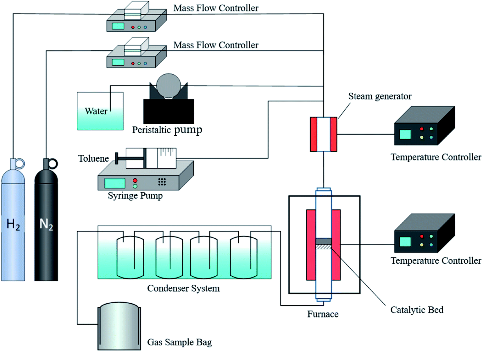 | ||
| Fig. 1 Schematic of the catalytic steam reforming device. | ||
Gaseous products were composed of H2, CO, CO2, and CH4. The main reactions were as follows:24
Steam reforming
| C7H8 + 7H2O → 7CO + 11H2 | (1) |
| C7H8 + 14H2O → 7CO2 + 18H2 | (2) |
Water gas reaction
| CO + H2O ⇌ CO2 + H2 | (3) |
Methane steam reforming
| CH4 + H2O ⇌ CO + 3H2 | (4) |
Carbon formation
| C7H8 → 7C + 4H2 | (5) |
Boudouard reaction
| 2CO ⇌ CO2 + C | (6) |
The conversion rate of toluene into CO, CO2 and CH4 was calculated by using the following formula.
 | (7) |
2.3 Catalyst characterization
D8 Advance (Bruker, Germany) was used to analyze the structure and phase of the catalyst with X-ray diffractometer. The test conditions were as follows: tube voltage of 40 kV, tube current of 30 mA, Cu target Kα rays, measurement range of 10–80°, and scan step size of 2° min−1.The determination of specific surface area and pore structure parameter was performed on ASAP2020 series automatic static physical adsorption instrument from Micromeritics Company in the United States. Before test, the sample was vacuum degassed at 300 °C for 4 hours in order to remove the moisture and impurity gases adsorbed in the sample. N2 was adsorbed and desorbed to obtain a nitrogen adsorption and desorption isotherm. The specific surface area of the catalyst was calculated according to the BET equation. The single-point pore volume at the relative pressure p/p0 = 0.995 was taken as the pore volume, and the pore size distribution was calculated by using the BJH method based on the desorption branch data of N2 adsorption–desorption isotherm.
Scanning electron microscopy (SEM) analysis was performed by using a Hitachi S-4800 electron microscope from Japan to characterize the microscopic morphology of the catalyst. The sample was evenly adhered to the sample stage with double-sided tape. After being sprayed with gold, sample was observed under an electron microscope with its acceleration voltage of 20 kV.
The H2-programmed temperature reduction (H2-TPR) test was performed on the TP-5080 chemical adsorption instrument (from Tianjin Xianquan Industry and Trade Development Co., Ltd.) to investigate the reduction properties of catalysts. The catalyst loading was set as 50 mg. Pre-treatment was conducted at 300 °C for 30 min in pure Ar to remove impurities. After cooling to room temperature, the catalyst was purged in 10% H2/Ar gas mixture at a flow rate of 30 mL min−1 until the baseline stabilized. The temperature rose to 900 °C at the rate of 10 °C min−1.
The CO2 temperature-programmed desorption (CO2-TPD) test was performed on a Tianjin TP-5076 chemisorption instrument to examine the basicity of the catalyst. The catalyst loading was set as 50 mg. He was used as the carrier gas. The catalyst was heated at the rate of 10 °C min−1 in a 10% H2/Ar atmosphere with a flow rate of 30 mL min−1, and the temperature was reduced for 1 hour to reach 600 °C. The catalyst was purged for 30 min, cooled down to 50 °C, adsorbed with pure CO2 (99.9%) for 30 min, was re-purged with helium for 30 min, and then temperature was raised to 900 °C at a rate of 10 °C min−1.
Thermogravimetric analysis (TGA) was performed to develop the TG and DTG thermogravimetric curves on a SDTQ600 TA synchronous thermal analysis (USA) analyzer. The thermogravimetric analyzer was used to examine the oxidation characteristics of carbon deposits on the catalyst before and after the reaction. Air was the oxidizing medium, and high-purity nitrogen was the protective gas. The air flow rate was 100 mL min−1. The test catalyst sample amount was about 10 mg, and temperature was raised to 900 °C at the heating rate of 10 °C min−1.
3. Results and discussion
3.1 Effect of Ni loadings
The effect of xNi/HZSM-5 catalyst on toluene steam reforming was evaluated under fixed bed and fixed experimental conditions. Catalytic experiments were performed at 700 °C, S/C ratio of 3, and WHSV of 3600 mL (gcat h)−1. Fig. 2a showed the change in toluene conversion rates of xNi/HZSM-5 catalyst with catalytic time at various loading doses. For 3Ni/HZSM-5 catalyst, the toluene conversion rate reached a maximum of 41.8% at the reaction time of 40 min, and then decreased to 36.4% after 120 min of reaction, indicating that the low Ni-loading catalyst had poor catalytic activity. The possible reason for this might lie in the lack of Ni active ingredients and the formation of coke during the catalytic reaction. When Ni loading was increased from 3 wt% to 6 wt%, the catalytic efficiency of toluene significantly was increased. For 6Ni/HZSM-5 catalyst, the toluene conversion rate maintained at 71.1% until the end of the reaction. The toluene conversion rate was continuously increased with the increase of the nickel loading. When the Ni loading was 9 wt%, the toluene conversion rate reached a maximum of 82.4%. However, after 60 min catalysis reaction by 9Ni/HZSM-5, the toluene conversion rate was significantly decreased to 76.5% at the end of the reaction, suggesting that the catalytic activity was reduced. The decrease in activity of catalyst might be caused by excessive Ni loading, which increased the particle size of Ni and decreased the specific surface area of the catalyst. The large size of Ni particles would accelerate coke formation, thus resulting in the decrease in catalytic activity of catalyst. It was reported that as the active metal loading increased, Ni particles on the surface of the catalyst were agglomerated, which reduced the resistance to carbon deposition of the catalyst and led to inactivation.25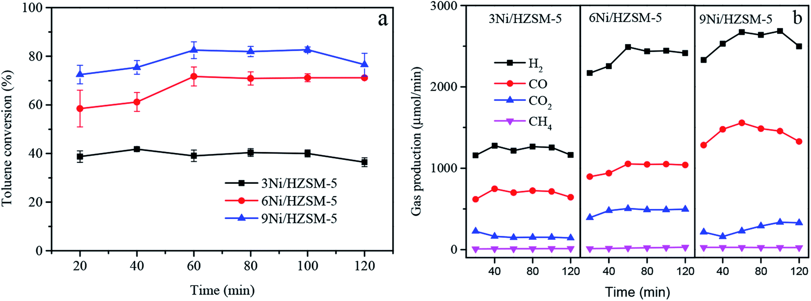 | ||
| Fig. 2 Effect of Ni loadings (a) toluene conversion and (b) product rate. | ||
Fig. 2b showed the generation rate of gaseous products over time with different Ni-loadings of Ni/HZSM-5 catalysts in the process of toluene steam reforming. The main gaseous products of toluene steam reforming consisted of H2, CO, CO2, and CH4. This indicated that reactions (1) to (6) might occur simultaneously in the toluene steam reforming. The ability of Ni-based catalyst to activate C–H and C–C bonds in hydrocarbon molecules was a critical factor for catalytic performance.26 The 3Ni/HZSM-5 catalyst exhibited the lowest gas generation rate with initial H2 and CO production rate of 1158 μmol min−1 and 617 μmol min−1, respectively. With the increase in Ni loading, H2 and CO production rates were increased in the process of toluene catalytic reforming. The 9Ni/HZSM-5 catalyst had the highest gas yield with initial H2 and CO production rate of 2332.6 μmol min−1 and 1283.7 μmol min−1, respectively. However, it was worth noting that the yield of H2 and CO were decreased after the 60 minute catalysis reaction by 9Ni/HZSM-5, and the yield of CO2 continued to increase. For 9Ni/HZSM-5 catalyst, carbon formation reaction (eqn (5)) and CO disproportionation reaction (eqn (6)) were increased in a positive direction, resulting in CO decrease and CO2 increase. In this experiment, the low Ni-loading Ni/HZSM-5 catalyst exhibited a poor steam reforming performance. The increase of Ni loading improved the catalytic activity of Ni/HZSM-5 catalyst.
3.2 Effect of MgO loadings
In order to investigate the effect of alkaline earth metal MgO replacing Ni on the performance of Ni/HZSM-5 catalyst in toluene steam reforming, three MgO loadings (3 wt%, 6 wt%, 9 wt%) were examined. The 9Ni/HZSM-5 catalyst with the highest catalytic activity was selected for comparison with 3Ni–MgO/HZSM-5 in order to explore optimal Ni substitute effect by MgO. As shown in Fig. 3a, the addition of MgO improved the catalytic activity of the 3Ni/HZSM-5 catalyst. As MgO loading increased, the toluene conversion rate was first increased, and then decreased. The initial toluene conversion rate of 3Ni–3MgO/HZSM-5 catalyst (70.1%) was close to that of 9Ni/HZSM-5 catalyst (71.5%), indicating that the steam reforming capacity of 3Ni–3MgO/HZSM-5 catalyst has reached the equal level of 9Ni/HZSM-5 catalyst. This might be attributed to the formation of (Ni, Mg)O solid solution active centers between Ni and MgO to improve the catalyst activity.27 The catalytic activity of the catalyst continued to increase with the increase in MgO loading. When the loading of MgO was 6%, the toluene conversion rate reached a maximum of 94.2%, and after 120 min, toluene conversion rate remained high (93.06%). The 3Ni–6MgO/HZSM-5 catalyst showed superior catalytic activity and stability. However, if the loading of MgO was further increased after 6% MgO loading, the toluene conversion rate was decreased. After 60 min catalysis reaction by 3Ni–9MgO/HZSM-5, the toluene conversion rate was decreased from 86.7% to 83.1%.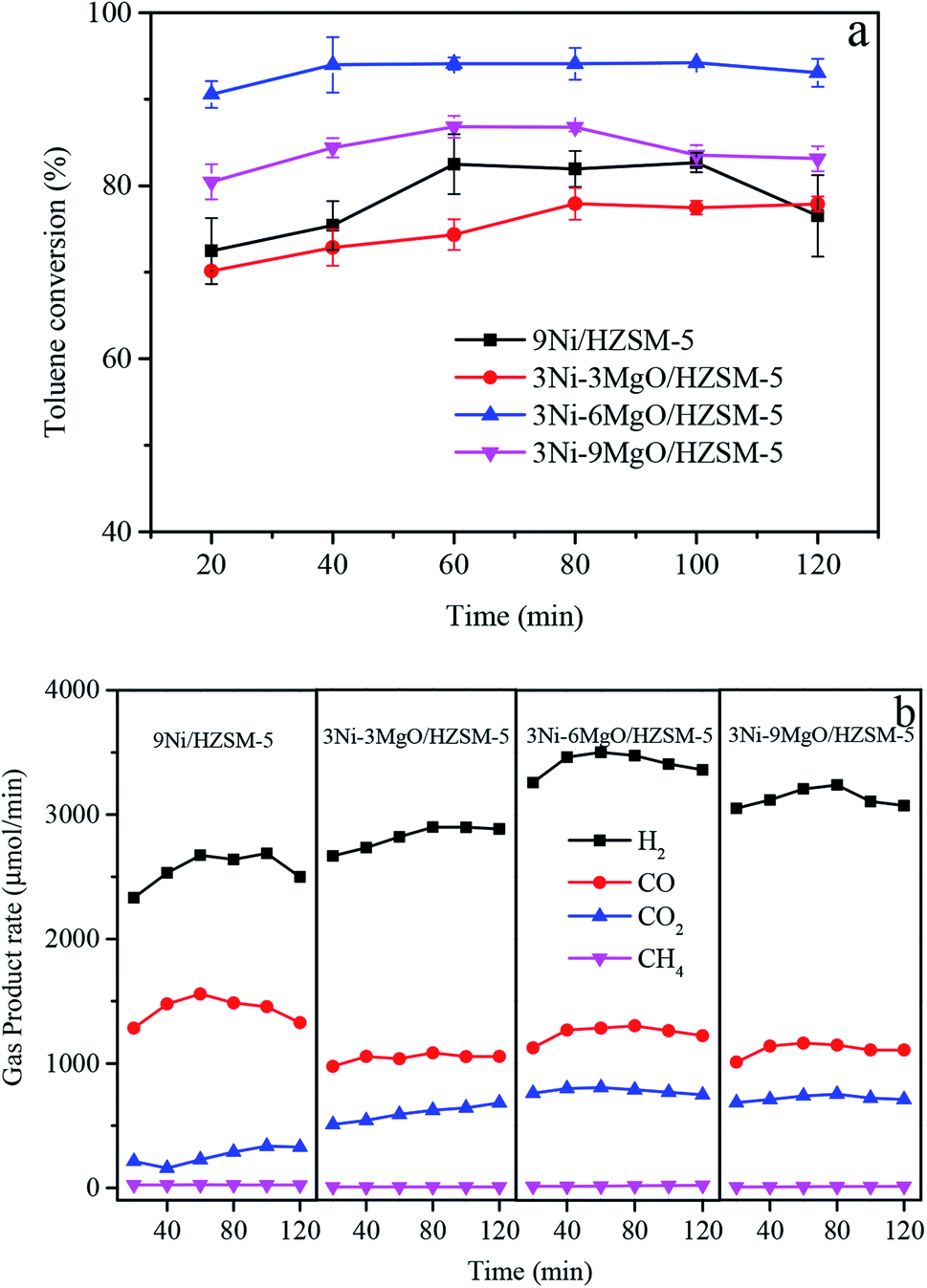 | ||
| Fig. 3 Effect of MgO loadings (a) toluene conversion and (b) product rate. | ||
Fig. 3b showed the generation rate of gaseous products over time with different MgO-loadings of 3Ni–MgO/HZSM-5 catalysts in the process of toluene steam reforming. For the 9Ni/HZSM-5 catalyst, H2/CO was relatively low, and there existed some unconverted toluene, suggesting that the steam reforming ability of high Ni-loading catalyst was limited. When the loading of MgO was increased from 3% to 6%, the initial H2, CO, and CO2 yields were increased from 2665.1 μmol min−1 to 3257.6 μmol min−1, from 974.1 μmol min−1 to 1126.5 μmol min−1, and from 507.1 μmol min−1 to 761.4 μmol min−1, respectively. However, it should be noted that when the loading of MgO was increased from 6% to 9%, the generation rates of all gas components were significantly decreased. The initial rate of H2 was decreased to 3048.5 μmol min−1, that of CO to 1007.8 μmol min−1, and that of CO2 to 681.8 μmol min−1. The 3Ni–6MgO/HZSM-5 catalyst exhibited the optimal syngas yield and toluene conversion rate. The above results indicated that when the MgO loading was increased to 6%, the catalytic reforming reaction on the surface of the catalyst was promoted (eqn (1)–(3)), and that the performance of steam reforming and water–gas shift reaction were enhanced, thus resulting in the increase in toluene conversion rate and H2 yield. However, excessive MgO loading (9%) might cause agglomeration of crystals or clogging of catalyst support pores. This study revealed that 3Ni–MgO/HZSM-5 catalyst of replacing Ni with MgO exhibited high catalytic performance and comparabled to the catalytic activity of 9Ni/HZSM-5 with high Ni loading. The optimal MgO loading of 6%.
3.3 Crystal form analysis
In order to investigate the effect of MgO replacing Ni on the crystal structure of the catalyst, crystal forms of catalysts were analyzed. The XRD patterns of the Ni/HZSM-5 and Ni–MgO/HZSM-5 catalysts before and after toluene steam reforming were shown in Fig. 4. In the fresh and used Ni/HZSM-5 catalysts, the characteristic peaks of Ni (2θ = 44.6°, 52.0°, 76.4°) were observed. The three peaks could be assigned to diffractions of the (111), (200), and (220) planes of metallic Ni, respectively.28 After the reaction, the characteristic peak intensity of Ni/HZSM-5 catalyst increased obviously. In Table 1, the crystal sizes of the Ni particles are calculated by the Scherrer equation using the peak at 2θ = 52°. For the Ni/HZSM-5 catalyst, the crystal size of Ni before and after the reaction increased significantly. Especially for 9Ni/HZSM-5, the crystal size of Ni increased from 21.9 nm to 31.4 nm. It was worth mentioning that the characteristic peak of graphitic carbon (2θ = 26.6°) was observed in the XRD patterns of spent 9Ni/HZSM-5, which indicated that the reaction produced a large amount of carbon deposition and covered the catalyst crystal surface.29 Since the radius of Ni2+ ions (0.070 mm) and Mg2+ (0.065 mm) were nearly the same, the two types of ions easily formed a solid solution.30 Therefore, the diffraction angles of MgO, NiO, and NiO–MgO solid solutions were basically similar. The characteristic peak of MgO (2θ = 36.8°, 42.9°, 62.4°) and that of NiO–MgO solid solution (2θ = 43.1°, 62.5°) were observed in the XRD patterns of fresh 3Ni–MgO/HZSM-5, and these two peaks were very close. Only one diffraction peak of Ni (2θ = 52.0°) was observed on the surface of Ni–MgO/HZSM-5 catalyst, which indicated that Ni was dispersed on the catalyst surface or Ni and MgO interacted to form NiMgO solid solution. The crystal size of Ni in the 3Ni–3MgO/HZSM-5 catalyst is 13.1 nm, which reaches the nanometer level. The 3Ni–6MgO/HZSM-5 catalyst with the highest catalytic activity had similar Ni crystal size before and after the reaction, which were 15.6 nm and 18.3 nm, respectively. This indicated that the crystal size of the catalyst after MgO replaced Ni had certain advantages for the catalyst activity.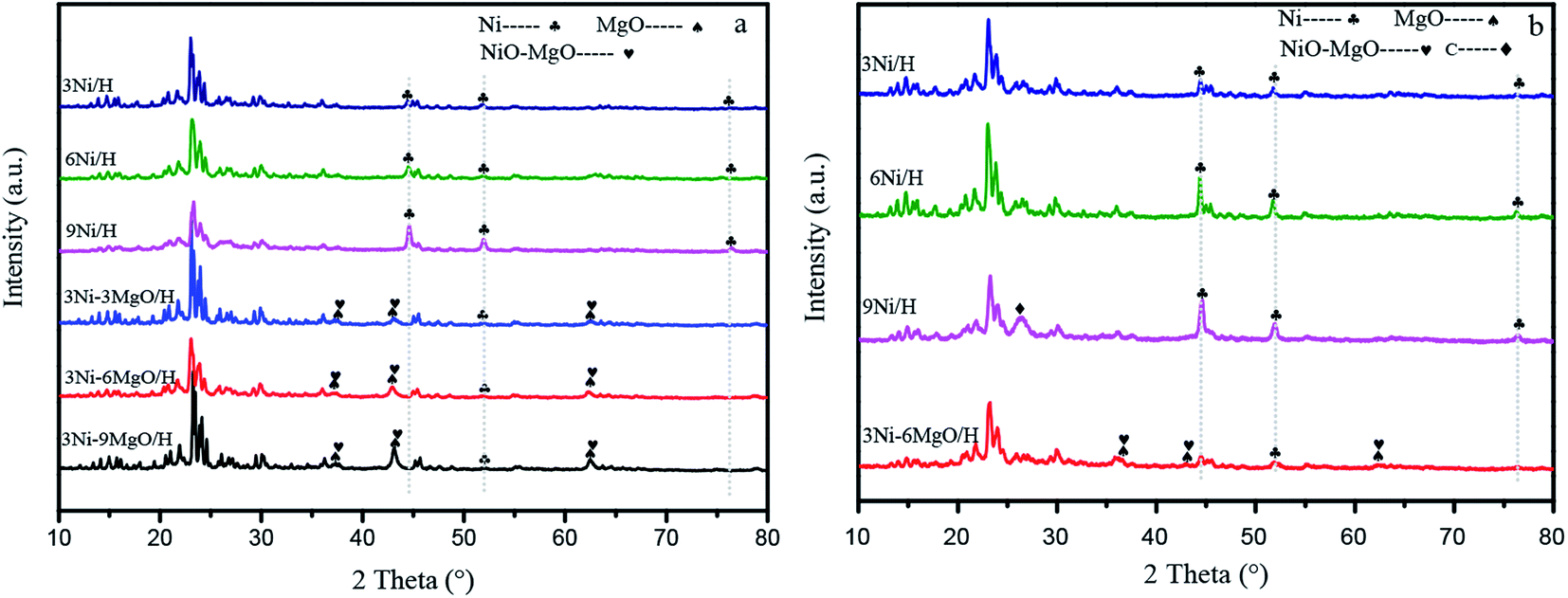 | ||
| Fig. 4 XRD patterns of (a) fresh and (b) used catalysts. | ||
| Catalyst | Ni crystal size (nm) | |
|---|---|---|
| Before reaction | After reaction | |
| 3Ni/HZSM-5 | 16.1 | 21.6 |
| 6Ni/HZSM-5 | 18.3 | 23.3 |
| 9Ni/HZSM-5 | 21.9 | 31.4 |
| 3Ni–3MgO/HZSM-5 | 13.3 | — |
| 3Ni–6MgO/HZSM-5 | 15.6 | 18.3 |
| 3Ni–9MgO/HZSM-5 | 22.7 | — |
3.4 Pore structure analysis
Table 2 showed the specific surface areas and pore structure parameters of 3Ni–MgO/HZSM-5 catalysts with different MgO loadings. As shown in Table 2, the pore structure of 3Ni/HZSM-5 catalyst was similar to that of the original HZSM-5, indicating that the incorporated Ni was evenly dispersed on the catalyst surface. With the addition of MgO, the specific surface area and micropore volume of the catalyst were gradually decreased. However, the mesopore volume, total volume, and pore diameter of the catalyst were gradually increased. These observation results might be attributed to MgO's entering the wall and pores of the carrier and combining with the active site Ni. In addition to specific surface area, pore volume, and pore size, micropore volume was another factor related to metal agglomeration.31 High pore volume contributed to reducing metal agglomeration and increasing active sites and gas exchange during catalytic reforming.32 When the MgO loading increased from 3% to 6%, no significant change in micropore volume was observed, indicating that the ability of catalyst to adsorb the reactants did not change. When the loading was increased to 9%, the significant change in pore structure was observed as follows: the micropore volume was decreased from 0.08 m3 g−1 to 0.06 m3 g; the BET surface area was decreased from 260 m2 g−1 to 184 m2 g; and the pore particle size increased from 2.3 nm to 3.9 nm. The results showed that excessive addition of MgO (9%) lowered micropore volume and specific surface area, thus inhibiting the adsorption of reactants and metal dispersion on the catalyst, finally resulting in the reduction in the catalytic activity.| Catalyst | SBET (m2 g−1) | Vtotal (cm3 g−1) | Vmicro (cm3 g−1) | Vmeso (cm3 g−1) | Pore size (nm) |
|---|---|---|---|---|---|
| HZSM-5 | 278 | 0.16 | 0.10 | 0.05 | 2.3 |
| 3Ni/HZSM-5 | 260 | 0.15 | 0.10 | 0.05 | 2.3 |
| 3Ni–3MgO/HZSM-5 | 232 | 0.16 | 0.08 | 0.07 | 2.8 |
| 3Ni–6MgO/HZSM-5 | 200 | 0.15 | 0.08 | 0.07 | 3.1 |
| 3Ni–9MgO/HZSM-5 | 184 | 0.18 | 0.06 | 0.11 | 3.9 |
3.5 Surface topography analysis
Fig. 5 showed SEM images before and after MgO added to the Ni-based catalyst. The MgO loading had an obvious effect on the overall morphology of the catalyst. The 3Ni/HZSM-5 catalyst had a smooth crystal structure surface with a small amount of fine particles attached (Fig. 5a). These fine particles might be the active sites of metallic Ni. The addition of MgO led to significant change in the morphology of the catalyst. Some large particles appeared on the surface of 3Ni–3MgO/HZSM-5 catalyst (Fig. 5b), which might be the formed NiO–MgO solid solution. These large particles facilitated the interaction between the catalyst and toluene, thus improving the catalytic reaction performance. The surface of the 3Ni–6MgO/HZSM-5 catalyst became dense, and obvious layered structures were observed on catalyst surface (Fig. 5c), which might provide more sites for catalytic reactions. A great amount of mental agglomeration was observed on 3Ni–9MgO/HZSM-5 catalyst surface (Fig. 5d). With the addition of MgO, number of particles was significantly increased on the catalyst surface. Some small holes or micropores were fused to form mesopores and macropores, eventually leading to an increase in the pore size. This was consistent with the results of pore structure analysis. However, the excessive MgO loading caused metal agglomeration, which led to the blockage of the pores, preventing the reaction gas from diffusing into the catalyst support, eventually resulting in a reduction in catalytic activity.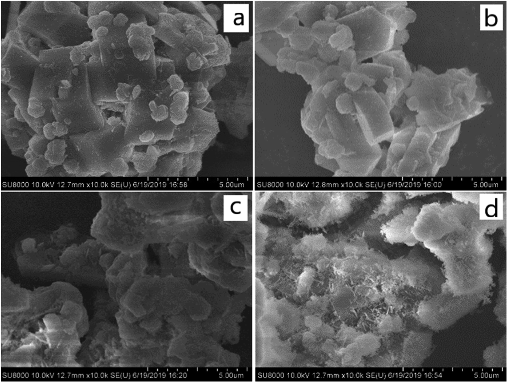 | ||
| Fig. 5 Surface morphology of Ni-based catalyst with and without MgO load. (a) 3Ni/HZSM-5; (b) 3Ni–3MgO/HZSM-5; (c) 3Ni–6MgO/HZSM-5; (d) 3Ni–9MgO/HZSM-5. | ||
3.6 Catalyst reduction analysis
In order to reveal the effect of MgO replacing Ni on Ni species on the surface of Ni/HZSM-5 catalyst, H2-programmed temperature reduction (H2-TPR) test was performed. As shown in Fig. 6, the reduction peak of Ni/HZSM-5 catalyst appeared at 430 °C.33 TPR chart of the Ni–MgO/HZSM-5 catalyst displayed one broad peak at about 518 °C, another broad peak at about 667 °C, and one strong peak at about 876 °C. One previous study reported that when temperature was above 600 °C, some NiO gradually diffused into the MgO lattice, which might form a NiO–MgO solid solution, that when temperature was above 1000 °C, some NiO was reduced to form a NiO–MgO solid solution, since Ni2+ was dissolved in the MgO lattice.34 This was consistent with our findings that the addition of MgO changed the Ni reduction temperature of the 3Ni/HZSM-5 catalyst and the shift of some NiO reduction peaks towards high temperature. These results might be attributed to the Ni and MgO interacted to form NiMgO solid solution. The reduction peak of 3Ni–6MgO/HZSM-5 catal was observed at 850–900 °C, which indicated the existence of NiO and MgO solid solutions. Besides, within the temperature range of 450–650 °C, the Ni–MgO/HZSM-5 catalyst showed a low intensity Ni species peak, indicating that Ni particles were highly dispersed on the surface of MgO and they were on the nanometer scale.35 These highly dispersed nano-sized Ni particles might contribute to enhancing catalytic reforming of Ni–MgO/HZSM-5 catalysts.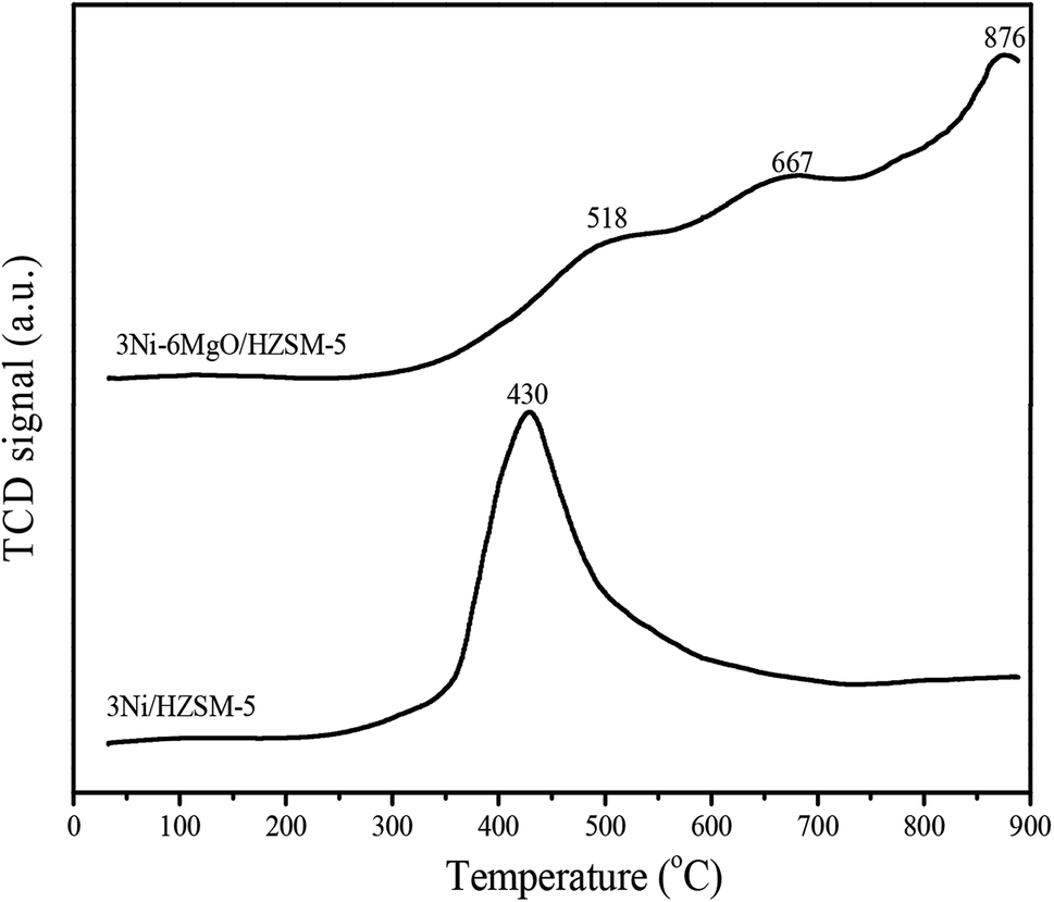 | ||
| Fig. 6 H2-TPR of 3Ni/HZSM-5 and 3Ni–6MgO/HZSM-5 catalysts. | ||
3.7 Catalyst alkaline analysis
In order to investigate the effect of the MgO replacing Ni on the strength of the basic sites of the Ni/HZSM-5 catalyst, a CO2-TPD analysis was performed. Theoretically, basic sites on the catalyst surface could promote the chemical adsorption of CO2, thus accelerating the Boudouard reaction in the reverse direction (2CO ⇌ CO2 + C) and reducing the formation of coke on the catalyst surface.36 The CO2-TPD curves of the two catalysts were shown in Fig. 7. The desorption peak of CO2 at the low-intensity basic site appeared within the range of 100–350 °C, which was attributed to the bicarbonate derived from the interaction of CO2 and weakly basic hydroxyl.37 In the CO2-TPD spectrum of 3Ni/HZSM-5, the CO2 desorption peak at a weakly alkaline site appeared at about 135 °C. The CO2 desorption peak of MgO-loading 3Ni–6MgO/HZSM-5 catalyst appeared at 148 °C, and shifted slightly to a high temperature region. According to the area of the CO2 desorption peak, the basic strength of 3Ni–6MgO/HZSM-5 was higher than that of 3Ni/HZSM-5. The results showed that MgO load enhanced the surface basicity of the catalyst and improved the catalyst's ability to adsorb CO2. The improved steam reforming performance of the 3Ni–6MgO/HZSM-5 catalyst revealed by Ni–MgO/HZSM-5 catalytic activity test results might be attributed to the high basic strength. The increase in the basicity of the catalyst contributed to enhancing the steam–carbon reaction and reducing the formation of coke on the surface of catalyst.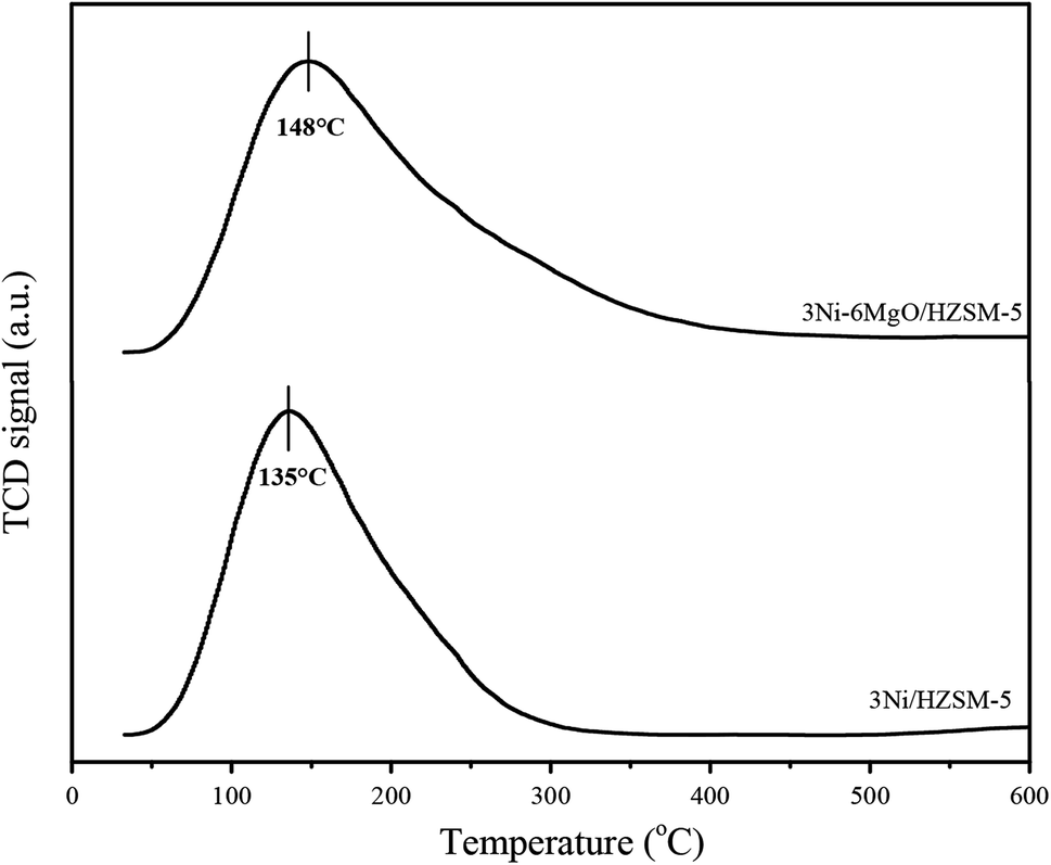 | ||
| Fig. 7 CO2-TPD of 3Ni/HZSM-5 and 3Ni–6MgO/HZSM-5 catalysts. | ||
3.8 Carbon deposition analysis of spent catalyst
In order to investigate the effect of MgO replacing Ni on the carbon deposition resistance of the catalyst, Thermogravimetric analysis (TGA) was performed with spent Ni/HZSM-5 and Ni–MgO/HZSM-5 catalysts. As showed in Fig. 8, the thermogravimetric curve consisted of three stages. The first stage was the drying stage at 0–200 °C, during which water vapor on the catalyst surface was volatilized and the thermogravimetric curve was decreased. The second stage was the oxidation stage at 350–450 °C, during which Ni simple substance was oxidized to NiO, and the increase in weight resulted in the rise of the thermogravimetric curve. The third stage was within temperature range of 500–700 °C, during which the coke on the catalyst surface burned and the thermogravimetric curve was significantly decreased. For Ni/HZSM-5 catalyst, the carbon deposition on the catalyst surface was increased with the increased Ni loading. The great amount of formed coke (up to 18 wt%) was observed on the surface of 9Ni/HZSM-5, indicating severe carbon deposition problem of 9Ni/HZSM-5 catalyst. By adding MgO, the coke content on the catalyst surface was significantly reduced. With the increase of MgO loading, coke formation was first decreased, and then increased. When MgO loading was 6%, the minimum amount of coke (only 0.46 wt%) was formed on the catalyst surface. Compared with the single-metal Ni/HZSM-5 catalyst, the MgO-modified Ni–MgO/HZSM-5 catalyst exhibited better carbon deposition resistance, which might be attributed to the fact that the addition of basic MgO increased the catalyst's ability to chemisorb CO2, thus contributing to the removal of amorphous carbon.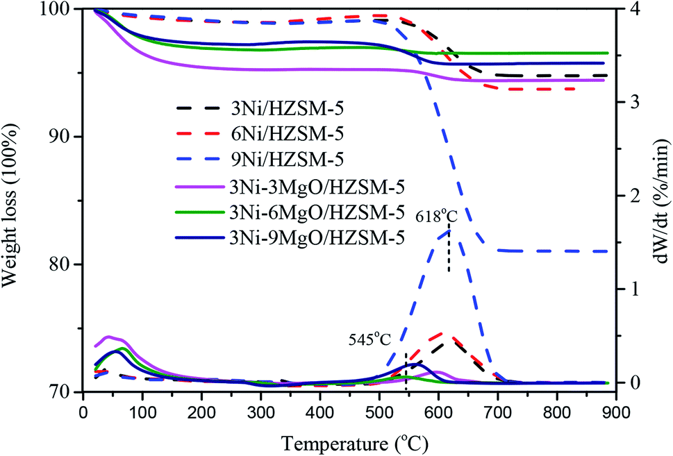 | ||
| Fig. 8 TGA graphs of spent Ni/HZSM-5 and 3Ni–MgO/HZSM-5 catalysts. | ||
In the DTG curves of Ni/HZSM-5 and Ni–MgO/HZSM-5 catalysts, only a wide carbon oxidation peak was observed in the range of 400–800 °C after the reaction. The wide peak at about 625 °C exhibited maximum intensity. The previous study indicated that the carbon deposited on the catalyst surface fell into two types: amorphous carbon and filamentous carbon. Amorphous carbon with low activity was oxidized at a temperature below 500 °C.38 Carbon oxidized at 500–650 °C was filamentous carbon.39 Our results showed that the coke on the surface of the catalyst after the reaction was mainly filamentous. In addition, the combustion temperature of carbon deposited on Ni/HZSM-5 catalyst was higher than that of carbon deposited on the catalyst modified by MgO, indicating that the addition of MgO converted the ordered carbon on the catalyst surface into disordered carbon.
The comparisons of catalytic performances were listed in Table 3. Hence, the 3Ni–6MgO/HZSM-5 catalyst in our work showed a good catalytic performance for toluene steam reforming. Compared with higher Ni-loading catalysts in the reference, MgO replaced Ni has a similar catalytic activity. Compared with the Ni–Mg catalysts in the references, the catalytic performance of 3Ni–6MgO/HZSM-5 catalyst was equivalent and the coking rate was significantly reduced.
| Catalyst | Reaction conditions | Conversion/% | Coking rate/% | References |
|---|---|---|---|---|
| 3Ni–6Mg/HZSM-5 | S/C = 3, T = 973 K | 92.8 | 0.46 | This work |
| 3Ni/olivine | S/C = 3.5, T = 1063 K | 59 | 4.5 | 9 |
| 10Ni/γ-Al2O3 | S/C = 1.6, T = 923 K | 51 | 0.1 | 20 |
| 20Ni/γ-Al2O3 | S/C = 1.6, T = 923 K | 62 | 0.71 | 20 |
| 30Ni/γ-Al2O3 | S/C = 1.6, T = 923 K | 99 | 1.21 | 20 |
| 3Ni–1Ce–1Mg/olivine | S/C = 1, T = 1063 K | 93 | 3 | 9 |
| 10Ni/MgO–Al2O3 | S/C = 0.42, T = 1073 K | 100 | — | 16 |
| 12Ni–5Ce/Mg(Al)O | S/C = 0.5, T = 1073 K | 96.8 | 8.5 | 17 |
4. Conclusion
In this work, a low Ni-loading Ni/HZSM-5 catalyst added with alkaline earth metal MgO exhibited excellent performance in the steam reforming of toluene. After part of Ni was replaced with MgO, the excellent steam reforming performance of catalyst was achieved. When the MgO loading was 6%, the optimal catalytic performance was obtained, and the conversion rate of toluene was as high as 92.8%. Compared with the single-metal Ni/HZSM-5 catalyst, the MgO-modified Ni–MgO/HZSM-5 catalyst exhibited better carbon deposition resistance. The minimum amount of coke (only 0.46 wt%) was formed on the 3Ni–6MgO/HZSM-5 catalyst surface. The high catalytic performance of Ni–MgO/HZSM-5 might be attributed to the combination of Ni and Mg to form NiO–MgO solid solution active centers, thus enhancing the catalytic reactivity. The excellent anti-carbon deposition capability of the Ni–MgO/HZSM-5 catalyst might be attributed to the increased basicity on the catalyst surface due to the addition of MgO, which in turn increased catalyst's ability to adsorb CO2. Further, the MgO addition contributed to promoting the steam–carbon reaction and inhibiting cracking and polymerization reactions, thereby reducing carbon deposition on the catalyst surface. This study revealed the feasibility of replacing Ni with MgO and the potential mechanism of maintaining similar catalytic performance. This study also laid the theoretical foundation for the industrial application of nickel-based catalysts.Conflicts of interest
There are no conflicts to declare.Acknowledgements
This research was financially supported by Special Fund for Agro-Scientific Research in the public interest (201503135-11), the Major Projects of Technical Innovation of Hubei Province (2019ACA153) and the Fundamental Research Funds for the Central Universities (201910504073). The authors also acknowledge the extended help from the Analytical and Testing Center of Huazhong Agricultural University (HZAU).References
- S. R. Sinsel, R. L. Riemke and V. H. Hoffmann, Renewable Energy, 2020, 145, 2271–2285 CrossRef.
- Y. Zhu, B. Yi, Q. Yuan, Y. Wu, M. Wang and S. Yan, RSC Adv., 2018, 8, 19917–19929 RSC.
- D. H. Heo, R. Lee, J. H. Hwang and J. M. Sohn, Catal. Today, 2016, 265, 95–102 CrossRef CAS.
- M. L. Valderrama Rios, A. M. González, E. E. S. Lora and O. A. Almazán del Olmo, Biomass Bioenergy, 2018, 108, 345–370 CrossRef CAS.
- L. Devi, K. J. Ptasinski and F. J. J. G. Janssen, Biomass Bioenergy, 2003, 24, 125–140 CrossRef CAS.
- X. Ji, B. Liu, W. Ma, G. Chen, B. Yan and Z. Cheng, J. Anal. Appl. Pyrolysis, 2017, 123, 278–283 CrossRef CAS.
- G. Garbarino, A. Lagazzo, P. Riani and G. Busca, Appl. Catal. B Environ., 2013, 129, 460–472 CrossRef CAS.
- Q. Dong, H. Li, S. Zhang, X. Li and W. Zhong, RSC Adv., 2018, 8, 40873–40882 RSC.
- R. Zhang, H. Wang and X. Hou, Chemosphere, 2014, 97, 40–46 CrossRef CAS PubMed.
- Z. Zhang, L. Liu, B. Shen and C. Wu, Renew. Sustain. Energy Rev., 2018, 94, 1086–1109 CrossRef CAS.
- Y. Kathiraser, J. Ashok and S. Kawi, Catal. Sci. Technol., 2016, 6, 4327–4336 RSC.
- W. Tang, J.-P. Cao, F.-L. Yang, X.-B. Feng, J. Ren, J.-X. Wang, X.-Y. Zhao, M. Zhao, X. Cui and X.-Y. Wei, Energy Convers. Manage., 2020, 212, 112799 CrossRef CAS.
- J. Meng, Z. Zhao, X. Wang, J. Chen, A. Zheng, Z. Huang, G. Wei and H. Li, J. Energy Inst., 2019, 92, 1765–1778 CrossRef CAS.
- T. Ahmed, S. Xiu, L. Wang and A. Shahbazi, Fuel, 2018, 211, 566–571 CrossRef CAS.
- X. Zou, T. Chen, P. Zhang, D. Chen, J. He, Y. Dang, Z. Ma, Y. Chen, P. Toloueinia, C. Zhu, J. Xie, H. Liu and S. L. Suib, Appl. Energy, 2018, 226, 827–837 CrossRef CAS.
- B. Yue, X. Wang, X. Ai, J. Yang, L. Li, X. Lu and W. Ding, Fuel Process. Technol., 2010, 91, 1098–1104 CrossRef CAS.
- C. H. Zhang Yuwena, X. Lu, W. Ding and G. Zhou, Rare Met., 2009, 28, 582–589 CrossRef.
- V. Claude, J. G. Mahy, J. Geens and S. D. Lambert, Materials Today Chemistry, 2019, 13, 98–109 CrossRef CAS.
- A. A. Aboul-Enein, F. S. Soliman and M. A. Betiha, Int. J. Hydrogen Energy, 2019, 44, 31104–31120 CrossRef CAS.
- V. Claude, J. G. Mahy, S. Douven, S. L. Pirard, C. Courson and S. D. Lambert, Materials Today Chemistry, 2019, 14, 100197 CrossRef CAS.
- J. Shao, J. Zhang, X. Zhang, Y. Feng, H. Zhang, S. Zhang and H. Chen, Fuel, 2018, 224, 138–146 CrossRef CAS.
- G.-Y. Chen, C. Liu, W.-C. Ma, B.-B. Yan and N. Ji, Energy Fuels, 2015, 29, 7969–7974 CrossRef CAS.
- K. Nakamura, T. Miyazawa, T. Sakurai, T. Miyao, S. Naito, N. Begum, K. Kunimori and K. Tomishige, Appl. Catal. B Environ., 2009, 86, 36–44 CrossRef CAS.
- G. Oh, S. Y. Park, M. W. Seo, Y. K. Kim, H. W. Ra, J.-G. Lee and S. J. Yoon, Renewable Energy, 2016, 86, 841–847 CrossRef CAS.
- Z. Li, X. Hu, L. Zhang, S. Liu and G. Lu, Appl. Catal., A, 2012, 417–418, 281–289 CrossRef CAS.
- X. Zou, Z. Ma, H. Liu, D. Chen, C. Wang, P. Zhang and T. Chen, Fuel, 2018, 217, 343–351 CrossRef CAS.
- H. Yu, Y. Liu, J. Liu and D. Chen, Fuel, 2019, 254, 115622 CrossRef CAS.
- C. Shen, W. Zhou, H. Yu and L. Du, Chin. J. Chem. Eng., 2018, 26, 322–329 CrossRef CAS.
- E. Savuto, R. M. Navarro, N. Mota, A. Di Carlo, E. Bocci, M. Carlini and J. L. G. Fierro, Fuel, 2018, 224, 676–686 CrossRef CAS.
- Z. Alipour, M. Rezaei and F. Meshkani, J. Energy Chem., 2014, 23, 633–638 CrossRef.
- Z. Liu, R. Che, A. A. Elzatahry and D. Zhao, ACS Nano, 2014, 8, 10455–10460 CrossRef CAS PubMed.
- Z.-Y. Lim, C. Wu, W. Wang, K.-L. Choy and H. Yin, J. Mater. Chem. A, 2015, 4, 153–159 RSC.
- X. Li, B. Yan, J. Zhang, N. Xu, J. Tao, R. Zhang, B. Liu, Z. Sun and G. Chen, Int. J. Hydrogen Energy, 2018, 43, 649–658 CrossRef CAS.
- F. Arena, A. Licciardello and A. Parmaliana, Catal. Lett., 1990, 6, 139–149 CrossRef CAS.
- H. Arbag, Int. J. Hydrogen Energy, 2018, 43, 6561–6574 CrossRef CAS.
- X. Luo, Y. Hong, F. Wang, S. Hao, C. Pang, E. Lester and T. Wu, Appl. Catal. B Environ., 2016, 194, 84–97 CrossRef CAS.
- S. M. Pudi, P. Biswas and S. Kumar, J. Chem. Technol. Biotechnol., 2015, 91, 2063–2075 CrossRef.
- D. Liu, X. Y. Quek, W. N. E. Cheo, R. Lau, A. Borgna and Y. Yang, J. Catal., 2009, 266, 380–390 CrossRef CAS.
- N. Cakiryilmaz, H. Arbag, N. Oktar, G. Dogu and T. Dogu, Int. J. Hydrogen Energy, 2018, 43, 3629–3642 CrossRef CAS.
| This journal is © The Royal Society of Chemistry 2020 |