
 Open Access Article
 This Open Access Article is licensed under a Creative Commons Attribution-Non Commercial 3.0 Unported Licence
Stable green and red dual-color emission in all-inorganic halide-mixed perovskite single microsheets†
Manyi Zhonga,
Zhuang Zhaoa,
Yuan Luoa,
Fang Zhou*c,
Yuehua Penga,
Yanling Yina,
Weichang Zhou *ab and
Dongsheng Tangab
*ab and
Dongsheng Tangab
aSchool of Physics and Electronics, Key Laboratory of Low-dimensional Quantum Structures and Quantum Control of Ministry of Education, Hunan Normal University, Changsha 410081, People's Republic of China. E-mail: wchangzhou@hunnu.edu.cn
bKey Laboratory for Matter Microstructure and Function of Hunan Province, Synergetic Innovation Center for Quantum Effects and Application, Hunan Normal University, Changsha 410081, People's Republic of China
cDepartment of Basic Course, Hunan Police Academy, Changsha 410138, People's Republic of China. E-mail: zhoufang@smail.hunnu.edu.cn
First published on 13th May 2020
Abstract
Recently, all-inorganic perovskites have attracted tremendous attention due to their excellent optoelectronic properties and extensive potential applications. However, these perovskites usually show a single emission wavelength because of the high ionic migration. Herein, we synthesized all-inorganic halide-mixed perovskite CsPbBrxI3−x microsheets with high crystal quality using the anti-solvent solution method and observed extraordinary green and red dual-color emission in single CsPbBrxI3−x microsheets. Power dependent PL spectra reveal excitonic and defect related recombination features of CsPbBr3 and CsPbI3 for the green and red emission. Temperature dependent PL spectra indicated a distinctive exciton–phonon coupling strength in CsPbBrxI3−x microsheets compared with pure CsPbBr3 and CsPbI3. The PL dynamics showing longer emission lifetime further confirmed this conclusion. Our work not only provides a novel strategy to produce stable dual-color emission integration, but also promotes the fundamental insight into the emission dynamics and exciton/free carrier related photophysics in all-inorganic halide-mixed perovskites.
1 Introduction
In the last decade, lead halide perovskites have attracted a great deal of attention due to their excellent properties including long charge carrier diffusion length, high absorption coefficient, remarkable PL quantum yield, high defect tolerance and tunable bandgap over the entire visible spectral region.1–6 Benefiting from these merits, lead halide perovskites have been expected to be promising building blocks for high-performance electronic and optoelectronic devices.4,7–11 At present most of these perovskites show single-color emission.1,2,9,10,12 However, dual-colors or multi-colors integrated emission in a single perovskite is desired due to its significant application in a wide range such as white emission, color display, integrated optics etc.Three pathways have been applied to realize the dual-colors emission in cesium lead halide perovskites. Firstly, impurity doping is the straightforward method to endow semiconductor with novel optical and electronic functionalities. It have been reported that lead-halide perovskite nanocrystals exhibited the band-edge and dopant Mn ions emission simultaneously.13–15 The dual-colors emission intensity could be tuned by the dopant concentration. Secondly, addition of surface ligands also could introduce a new emission peak due to the interaction between the surface ligands and the host lattice. By adjusting the content of ligands on surface, the intensity of the emission peaks can be regulated effectively.16 Lastly, the spatially resolved CsPbX3 nanowire hetero-junctions can exhibit evident dual-colors or multicolors emission.6,17–20 Although achieving much harvest, these approaches to realize the dual-colors emission still have some shortcomings. For example, Mn2+ doping is nerveless for CsPbBr3 and CsPbI3. The surface ligands are restricted to the nanometer scale crystals while the heterogeneous structures suffered from the complex implementation.6,13–20 Therefore, hunting for efficient approach to realize the dual-colors emission in cesium lead halide perovskites is needed. Very recently, light-induced phase segregation is prevalent for organic–inorganic and all-inorganic halide-mixed perovskites. Under light irradiation, the halide-mixed perovskites degenerated into multi-domains with diverse composition and band gap due to the net migration of ions through halogen vacancies,21–29 yielding two or multi- PL peaks integration. Unfortunately, this phenomenon is unstable and the domains will recover to the original uniform phase quickly after turn off the light illumination.27–30
In this work, we exhibit the stable green and red dual-colors emission from a simple anti-solvent solution method synthesized CsPbBrxI3−x micro-sheet. Power and temperature dependent PL spectra were performed to reveal the green and red emission origin from the excitonic and defect related recombination of CsPbBr3 and CsPbI3, respectively. Further analysis of FWHM and peak intensity extracted from the temperature-dependent PL revealed the distinctive exciton–phonon coupling strength of two emission bands. Lattice stress induced by the I-rich domains may play an important contribution to this distinct change. These results not only provide a novel strategy to satisfy the need of multi-colors emission integration, but also promote the fundamental insight into the emission dynamics and exciton/free carriers related photophysics in all-inorganic halide-mixed perovskites.
2 Experimental section
2.1 Chemical reagents
All the chemicals and reagents, CsBr (99.5%, Aladdin), CsI (99.9%, Aladdin), PbBr2 (99.0%, Aladdin), dimethyl sulfoxide (DMSO, 99.9%, Macklin), N,N-dimethylformamide (DMF, 99.9%, Macklin), islpropanol (99.9%, Macklin), were used as received without any further purification.2.2 Synthesis procedures
Firstly, 0.1 mmol CsI and 0.2 mmol PbBr2 powder were dissolved into 4 mL of DMF. 0.1 mmol CsBr was dissolved into 2 mL of DMSO. Then, the CsI–PbBr2 and CsBr solution were mixed together. Finally, 50 μL of the as-prepared mixed solution was dripped on a silicon slice, which was placed next to a glass dish containing 9 mL islpropanol. Another glass dish with diameter of 10.5 cm was placed upside down to cover the silicon slice and the glass dish. The schematic diagram was shown in Fig. S1a.† The whole equipment was kept at 60 °C until all the solvent evaporated up. After tens of minutes, yellowish-brown precipitation can be observed by naked eye. The precipitated CsPbBrxI3−x microsheets were directly used for further characterization. Additional 5 μL γ-butyrolactone or 1,2-propylene carbonate was helpful for optimize the product. It is needed to note that all these processes were performed under atmospheric environment in the ultra-clean chamber.2.3 Structure and optical characterizations
Optical microscopy (Olympus BX53, integrated into the Raman spectrometer) and scanning electron microscopy (SEM, FEI Nova nanoSEM-450) were used to characterize the size and morphology of as-synthesized product. The chemical composition analysis was carried out using the energy-dispersive spectrometry (EDS, Oxford X-max 20, attached on the SEM). Powder X-ray diffraction (PXRD) measurement was performed at room temperature by Bruker D8 Discover diffractometer to determine the crystallographic phase structure. The steady-state PL spectra of individual microsheet were obtained using a high-resolution Raman spectrometer (LabRAM HR Evolution, Horiba JY) with 532 and 355 nm continuous wave (CW) lasers as excitation light sources. Here, the laser power is 0.2 mW and numerical aperture (NA) of the object is 0.8. The diameter of light spot equals to 1.22 λ/NA. The back scattered PL was collected. Liquid nitrogen cryogenic platform (Linkam THMS 600) was used for the temperature-dependent measurement. The time-resolved PL (TRPL) was collected by the time-correlated single-photon counting (TCSPC) system (PicoQuant GmbH, Picoharp 300) with a picosecond pulsed laser diode (Picoquant PDL 800-B, λ = 375 nm, 10–80 MHz) as the excitation source.3 Results and discussion
The CsPbBrxI3−x micro-sheets were synthesized by a simple anti-solvent solution method (as shown in Fig. S1a†). Here, isopropanol was chosen as the anti-solvent because it can form a neat morphology and would not damage apparently the optoelectronic performance of halide perovskites. As shown in Fig. S1b,† a large amount of CsPbBrxI3−x micro-sheets with yellowish-brown color have been obtained. The optical and SEM images in Fig. 1a and b confirmed the rectangular sheet-like morphology with a uniform yellowish-brown color and smooth surface. The width and length are tens of micrometers. Fig. S1c and d† showed the morphology of other samples. The chemical composition of as-synthesized micro-sheets was characterized by EDS. The micro-sheet was constituted by Cs, Pb, and halides (Br and I) with a ratio nearly to 1![[thin space (1/6-em)]](https://www.rsc.org/images/entities/char_2009.gif) :1:3 (Fig. 1c), although the proportion of iodine is only 1.47%. EDS mapping was further performed to investigate the element distribution. Fig. 1d–g showed the uniform distribution of Cs, Pb, Br and I. PXRD was used to determine the crystal structure. These observed diffraction peaks correspond to the (200), (110), (100) lattice planes of monoclinic phase CsPbBrxI3−x.31–33 The high intensity of (200) might indicate the preferential growth direction. The absence of diffraction peaks of PbBr2, CsBr, CsPbI3, and Cs4PbBr6 demonstrates the high purity and high crystalline of the as-synthesized CsPbBrxI3−x micro-sheets.33–35 It is noted that the minor iodine has little effect on the crystal structure. However, the inclusion of this minor iodine has important effect on the optical properties. The absorption spectrum of CsPbBrxI3−x micro-sheets shows an additional low-energy shoulder extending to 665 nm (∼1.85 eV) compared to CsPbBr3,32,36 demonstrating the remarkable variation of electronic band structure with even little iodine addition (the black curve in Fig. 1i). After consecutive irradiation (λ = 445 nm) for 90 min, the absorption spectrum shows a negligible change (the red curve in Fig. 1i), indicating that the irradiation did not induce large change in crystal structure or phase composition. Both the slight loss of green region and increase of the low-energy shoulder band show a signature of phase segregation, which is prevalent in organic–inorganic halide-mixed perovskites.21,26,37,38
:1:3 (Fig. 1c), although the proportion of iodine is only 1.47%. EDS mapping was further performed to investigate the element distribution. Fig. 1d–g showed the uniform distribution of Cs, Pb, Br and I. PXRD was used to determine the crystal structure. These observed diffraction peaks correspond to the (200), (110), (100) lattice planes of monoclinic phase CsPbBrxI3−x.31–33 The high intensity of (200) might indicate the preferential growth direction. The absence of diffraction peaks of PbBr2, CsBr, CsPbI3, and Cs4PbBr6 demonstrates the high purity and high crystalline of the as-synthesized CsPbBrxI3−x micro-sheets.33–35 It is noted that the minor iodine has little effect on the crystal structure. However, the inclusion of this minor iodine has important effect on the optical properties. The absorption spectrum of CsPbBrxI3−x micro-sheets shows an additional low-energy shoulder extending to 665 nm (∼1.85 eV) compared to CsPbBr3,32,36 demonstrating the remarkable variation of electronic band structure with even little iodine addition (the black curve in Fig. 1i). After consecutive irradiation (λ = 445 nm) for 90 min, the absorption spectrum shows a negligible change (the red curve in Fig. 1i), indicating that the irradiation did not induce large change in crystal structure or phase composition. Both the slight loss of green region and increase of the low-energy shoulder band show a signature of phase segregation, which is prevalent in organic–inorganic halide-mixed perovskites.21,26,37,38
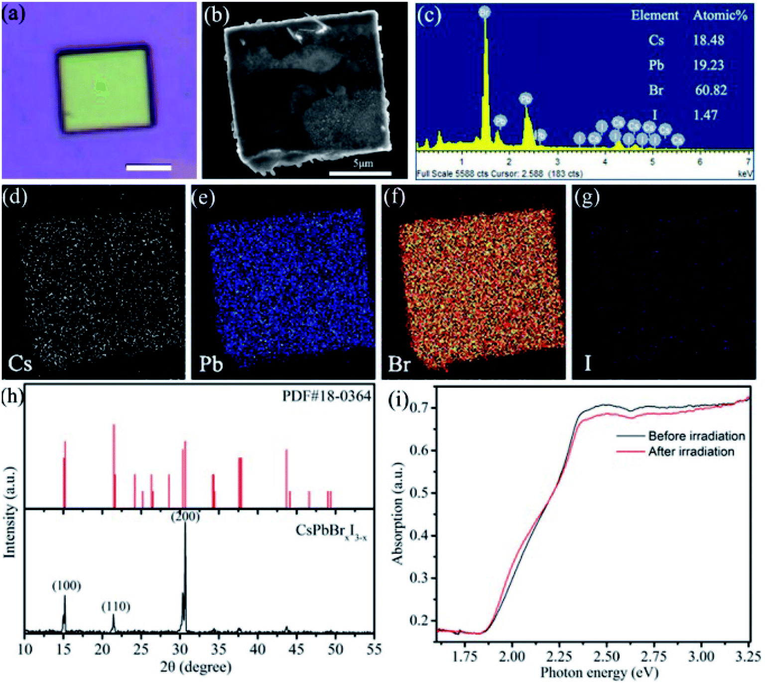 | ||
| Fig. 1 (a–c) Optical image, SEM and EDS of a single CsPbBrxI3−x microsheet. Scale bar in (a) is 5 μm. (d–g) EDS mappings of element Cs, Pb, Br and I. (h) PXRD patterns of CsPbBrxI3−x microsheets. (i) Absorption spectra of CsPbBrxI3−x microsheets before and after the light irradiation (λ = 445 nm). | ||
Fig. 2a is the evolution of PL spectra with illumination time for a single CsPbBrxI3−x microsheet, showing the dual-colors emission. The peak shift of high energy (2.3–2.4 eV) is negligible while its intensity reduces a little. Meantime, the low energy peak redshifts continually from ∼1.88 eV to ∼1.78 eV with increased intensity. It's reported that the cubic bulk CsPbI3 has a band gap of ∼1.8 eV (691 nm).9,32,39–41 Comparison with the PL of bulk CsPbI3 crystals, the present PL band shows a blue shift and there are several reasons contribution to this blue shift. First, quantum dots with small size usually cause the PL blue shift due to the quantum confinement effect. This is reasonable in the present case because the little content of iodine will yield the quantum dots-like structures under laser illumination, forming the compound of CsPbI3 QDs embedded into CsPbBr3 matrix. Secondly, a little bromine might doping into the CsPbI3 lattice to form CsPbI3−xBr3 alloy, yielding the PL blue shift due to the larger band gap of CsPbBr3. The significant redshift and enhanced intensity of the low energy peak confirm the occurrence of light induced phase segregation, as demonstrated in the absorption spectra. Similar redshift of PL spectra were prevalent in the halide-mixed counterparts.21–23,27,28,30,42–44 As revealed in previous studies that light irradiation induced local electric field or gradient carrier concentration, halide ions would migrate through the assistance of defects.22–27,42–46 For halide-mixed perovskites, migration of halide ions would form the phase segregation process due to the different activation energy of halide ions, yielding the segmented perovskites with diverse halide compositions and bandgaps.21–23,25,26,28–30,42,43,45 Therefore, PL peak shifts with varied intensity under light irradiation. In the present CsPbBrxI3−x micro-sheets, laser irradiation induced phase segregation give rise to the formation of local iodine-rich and bromine-rich domains, leading to the peak shifts and intensity variation of the two corresponding peaks. For convenience of the following discussion, we note the high and low energy peaks as Br-rich peak and I-rich peak, respectively. In the previous papers, the CsPbBr2I thin film showed a continuous red shifted peak position of the observed single PL band while the CsPbBrxI3−x micro-platelet demonstrated an intensity variation oppositely of the observed two peaks under laser excitation.42,45 For our CsPbBrxI3−x micro-sheets, the peak position shifts of the observed two peaks are not evident and the intensities of both peaks increase simultaneously, demonstrating the better stability of the green and red dual-emissions. Under laser irradiation, due to the laser irradiation induced phase segregation effect, the content and size of iodine-rich domains evolve into CsPbI3 with the illumination time, yielding the more evident shift of the low energy peak. While for the high energy peak, the phase segregation process almost has no effect on the content and size of CsPbBr3 lattice host, endowing the little shift of high energy peak with the illumination time.42,45
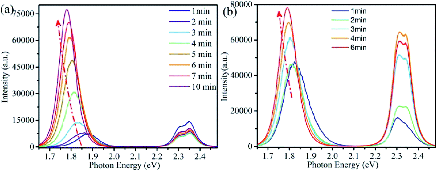 | ||
| Fig. 2 (a) PL spectra evolution of a single CsPbBrxI3−x microsheet with the irradiation time of CW laser (wavelength λ = 355 nm and power P = 0.2 mW). (b) PL spectra of the same CsPbBrxI3−x microsheet after stored in desiccator for 72 h. | ||
In addition to phase segregation, light irradiation can also induce defect healing effect, resulting in the increase of both PL intensity and lifetime.24,47–50 To gain further insight into the time-dependent PL spectra, we performed Lorentz decomposition for Br-rich peaks while Gaussian decomposition for I-rich peaks. As shown in Fig. S2a,† the Br-rich peak decomposed into two adjacent peaks at 2.353 and 2.302 eV with full width at half maximum (FWHM) of 64 and 59 meV. The two peaks varied in a synchronous way that their peak energy and FWHM decreased monotonically while the peak intensity weakened first and then increased gradually. The I-rich peak also decomposed into two adjacent peaks (Fig. S2b†). These two adjacent peaks firstly centered at 1.881 and 1.873 eV with FWHM of 87.42 and 138.49 meV. Subsequently, under continuous laser irradiation, the two peaks gradually shifted to low energy position with different rate. Their FWHM decreased and intensity increased in inhomogeneous ways. Finally, the two peaks fixed at 1.779 and 1.785 eV and their FWHM decreased to 66.65 and 119 meV.
Generally, FWHM could be affected by crystal size, carrier–phonon interaction or the defect-related inhomogeneous broadening.15,32,51–53 For the as-synthesized CsPbBrxI3−x micro-sheets, the decrease of FWHM could be induced by either phase segregation induced size increases of I-rich domains or defect healing effect caused restore of defects. It is worth to note that Lorentz decomposition was suitable for the fitting of Br-rich peak while Gaussian decomposition was used for I-rich peak fitting. Gaussian decomposition does not yield a good fit to Br-rich peak when just consider two peaks. The case is similar for Lorentz decomposition in I-rich peak. Therefore, this result suggests that the defects or impurities related recombination of I-rich peak and also approves the happen of laser induced defect healing.
More interesting, as a significant difference from lots of the previous reports, which demonstrated that segregated segmentations would recover quickly to the uniform alloy phase after stored in dark for tens of minutes,27–30,54 the present I-rich peak does not completely recover to the initial position shown in Fig. 2a after stored in desiccator for 3 days, as shown in Fig. 2b. Meanwhile, the PL spectra recover to a similar profile after laser irradiation, indicating the high stability of the dual-colors emission from CsPbBrxI3−x microsheets.
Another interesting observation is that both Br-rich peak and I-rich peak are composed by two adjacent peaks. This observed phenomenon is not an occasional case,32,40,55–57 and its origin is still in dispute. To have a look into the nature of the four constitutive peaks, we performed the laser power-dependent PL. It is well known that the near-band-edge luminescence intensity IPL is proportional to the laser power P (IPL ∝ Pα). Generally, the coefficient α is 1 < α < 2 for free- and bound-exciton emission while less than 1 for donor–acceptor pair recombination.9,31,58 We collected the PL spectra under the excitation of 355 nm CW laser with a series of power between 0.002–0.2 mW at the same position. The comparison of PL spectra excitated by high and low excitation power is shown in Fig. S3a and b.† The lower excitation power yields smaller influence on CsPbBrxI3−x micro-sheets. That is, laser induced defect healing has tiny influence on PL intensity. We carried out this strategy after completion of phase segregation to avoid its influence as much as possible. The I-rich peak fixed at ∼1.78 eV. Fig. 3a is the power-dependent PL spectra and Fig. 3b and c are the corresponding fitted curves of PL intensity versus excitation power. The coefficient α are determined to be 1.29 and 1.205 for the two Br-rich peaks whereas 1.06 and 0.95 for the two I-rich peaks. So, two Br-rich peaks derive from excitonic emission.31,32 But for two I-rich peaks, the coefficient α was complex. To exclude the possible influence from Br-rich domains to I-rich domains, we collected a series of PL spectra at the same point under excitation of 532 nm laser with power of 0.005 mW, 0.05 mW, 0.5 mW and 1.6 mW (Fig. S4†). The corresponding α are 0.69 and 0.57, indicating that the two I-rich peaks shall origin from donor–acceptor pair recombination. Fig. S5† is the PL spectra and corresponding fitting curves of another sample, which also support this conclusion. This conclusion is consistent with the behavior of FWHM in Fig. 2a.
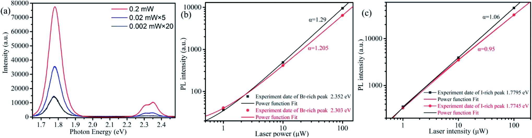 | ||
| Fig. 3 (a) Power-dependent PL spectra of a single CsPbBrxI3−x microsheet under the 355 nm CW laser excitation. (b and c) The log–log plot of PL intensity versus laser power for the two Br-rich peaks and I-rich peaks extracted from Fig. 3a (color points). The color solid lines are the fitted curves using power function. | ||
For organic–inorganic hybrid halide-mixed perovskites, it's believed that the repetition rate play a more important role on the phase separation than the laser power.27,28 For the all-inorganic halide-mixed perovskites, such as CsPbBrxI3−x nanowires, it has been reported that no photoinduced phase segregation was observed under excitation of femtosecond pulsed laser (λ = 400 nm, 150 fs, 1 kHz).17 In this work, we used a picosecond laser diode (λ = 375 nm, 10 MHz, 60 ps, ∼200 pJ per pulse) to excite the single CsPbBrxI3−x micro-sheet. The irradiation time dependent PL was shown in Fig. 4a. Obvious red shift of I-rich peaks can be observed. Peak decomposition also revealed that the I-rich peak contained two components with decreased FWHM under increased pulsed laser excitation time (Fig. S6b†). However, the Br-rich peaks contained only one peak (Fig. S6a†), disagreeing with the results of CW laser excitation. The reason may attribute to the different interaction way within the CsPbBrxI3−x microsheet for pulsed laser and CW laser.27,28,30 The time-resolved PL of a single CsPbBrxI3−x microsheet was measured to obtain more information about the photo-excited carrier dynamics, as shown in Fig. 4b and c. These PL decay curves can be fitted with an exponential function: I(t) = A1exp(−t/τ1) + A2exp(−t/τ2) + …, here τn represents the decay time of two kind of recombination mechanism, An is the amplitudes of τn.24,36,49,50,59 These decay results and the corresponding curves have been fitted well, as shown in Tables S1 and S2.† It's distinct that the dominant components continuously increase for both Br-rich (τBr1 and τBr2) and I-rich (τI1 and τI2) peak under laser excitation, indicating the decrease of defect under excitation of laser,24,49,50 consistent with the results of time- and power-dependent PL spectra. It has been proposed that migration of halide ions is defect-mediated.27,29,54,57 Decreased defect concentration would reduce light induced ion migration. To the negative value of amplitudes A2, there was proposed that it stands for a rise kinetics of PL signal, indicating a continuous population after laser excitation.59 Negative value of amplitude could be treated as a signature of energy transfer.59 Due to the bigger bandgap of Br-rich phase than the I-rich phase, re-absorption and carrier transfer from Br-rich phase to I-rich phase is reasonable. In fact, we do observe the stronger emission intensity of I-rich phase than the Br-rich phase despite the minor value of I/Br. In addition, the two lifetime components of Br-rich phase are smaller than the counterparts of CsPbBr3 quantum dots.36,39 Such decreased lifetime was also observed in MAPbBr3/Ti3C2Tx due to energy transfer from MAPbBr3 to Ti3C2Tx.59,60 For the all amplitudes, their variation reflect the population change to corresponding recombination mechanism, which could be influenced by either irradiation induced defect healing or ion migration generated defects (vacancies or interstitials).23,24,42,45,46 As it's believed that with the aid of halogen vacancies, the laser induced electric field or gradient carrier concentration can drive halide anion to migrate and rearrange, yielding the phase segregation into I-rich phases and net CsPbBr3 lattice under sufficient long excitation.23,27,29,42,45 This evolution could be interpreted as the arrangement of I-ions from dispersive to aggregative and the variation of Br-vacancy and interstitial density.24,42,54,61 As a result, the τBr1 can be assigned to excitonic recombination from net CsPbBr3 lattice. The decrease of τBr1 at the first stage is due to the increasing density of vacancy induced by ion migration. Then benefitting from restoration of CsPbBr3 crystal lattice by laser, τBr1 would increase.36,61 τBr2 could be assigned to impurity (I−) or defects induced nonradiative recombination.36,61 Its' amplitude decreased due to aggregation of I−. At the same time, τI1 and τI2 lengthen with the enhancement of I-rich phase.40,59 The third (τI3) has lesser importance but behaves in a bizarre way. It may play the aggregative role of other subordinate and complex mechanisms.
 | ||
| Fig. 4 (a) Evolution of PL spectra with irradiation time for a single CsPbBrxI3−x microsheet under pulse laser (λ = 375 nm, 10 MHz repetition rate, ∼200 pJ per pulse). (b and c) The corresponding PL decays of Br-rich peak and I-rich peak under different irradiation time. | ||
For CsPbBrxI3−x micro-sheets, the influence induced by iodine ions to temperature dependent PL spectra has not been investigated. Here, we measured the temperature dependent PL spectra from 123 to 273 K with a temperature interval of 25 K (Fig. 5a). According to the reports that light induced phase instability can be suppressed at the temperature lower than 250 K for CsPbBrxI3−x film and nanowire,62 we cooled the sample to 123 K firstly to suppress the influence from laser excitation. Lorentz/Gaussian decomposition was used to fit the Br-rich (Fig. S7a†) and I-rich peaks (Fig. S7b†). The peak positions, FWHM and PL intensity versus temperature of all the four peaks derived from the peak decomposition were plotted in Fig. 6.
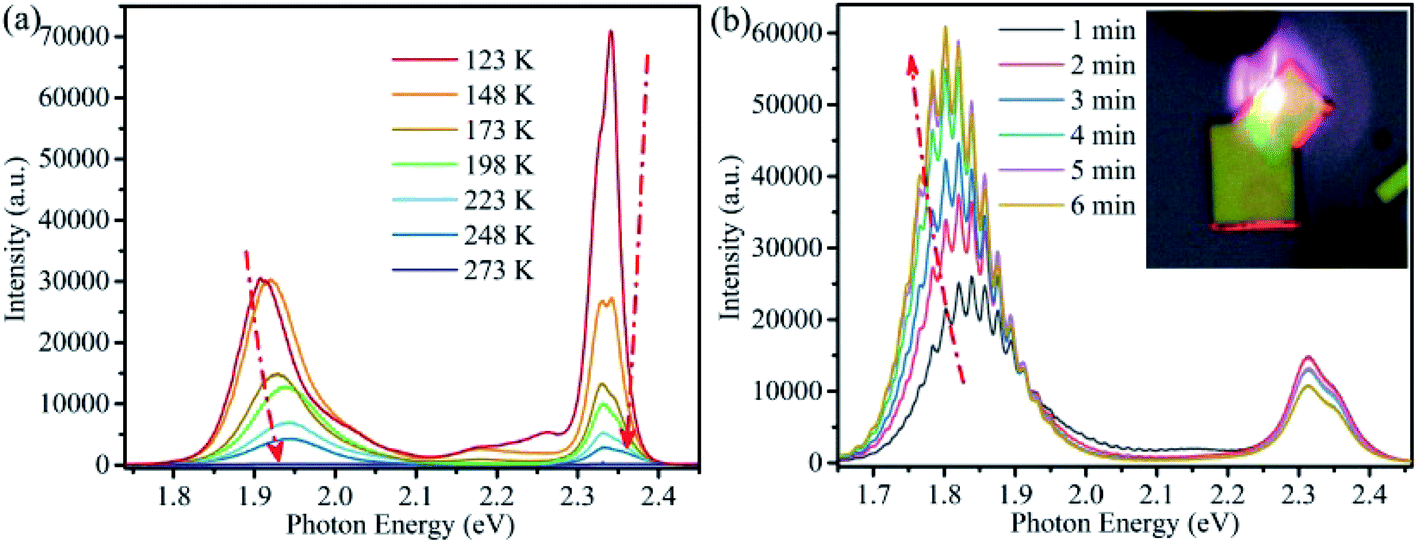 | ||
| Fig. 5 (a) Temperature dependent PL spectra of a single CsPbBrxI3−x microsheet. (b) Evolution of PL spectra with irradiation time of another CsPbBrxI3−x microsheet. Inset is the corresponding emission image, showing evident optical waveguide. | ||
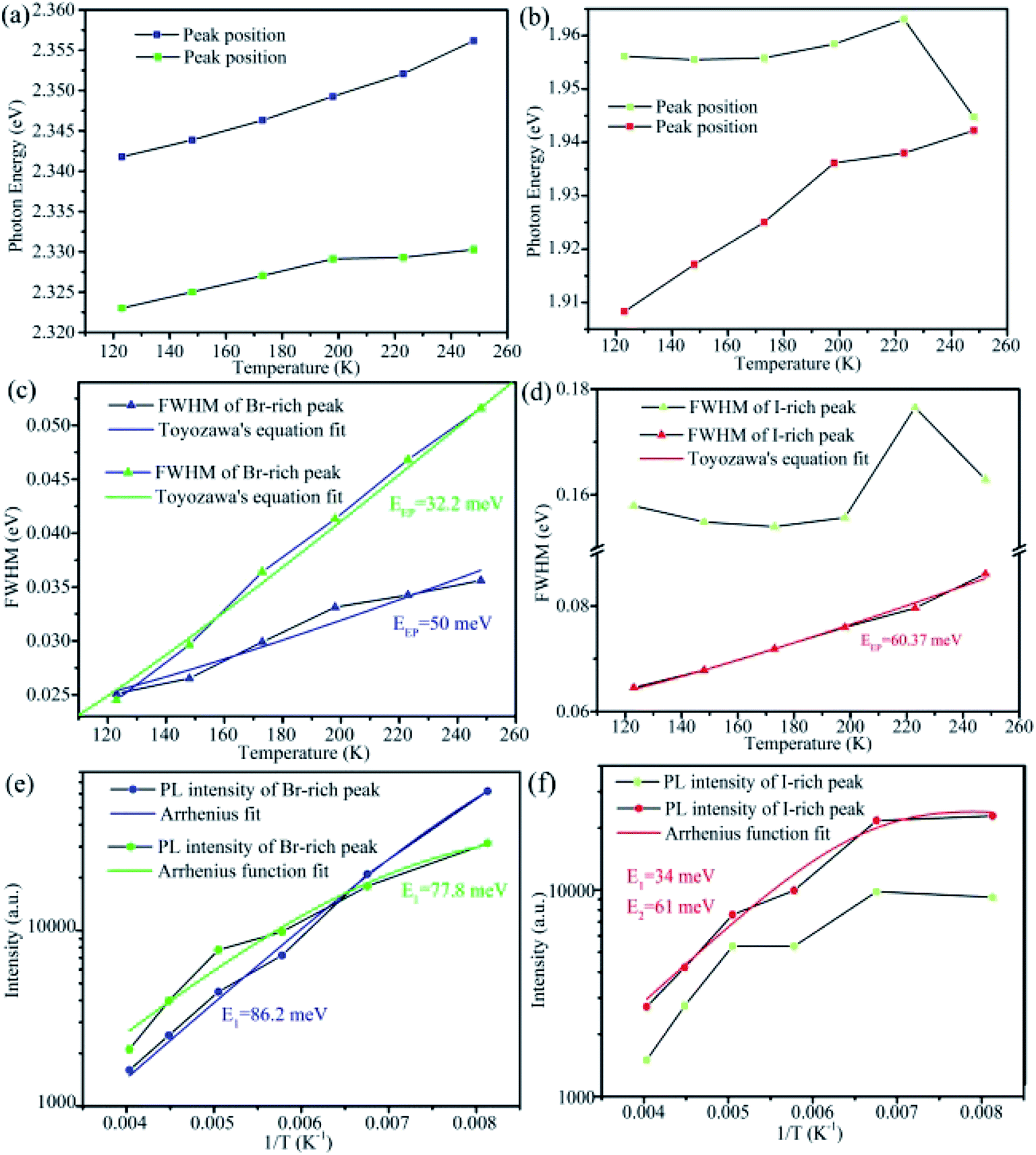 | ||
| Fig. 6 (a and b) Photon energy of Br-rich and I-rich peaks versus temperature, respectively. (c and d) FWHM of Br-rich and I-rich peaks versus temperature. The solid curves are the fitted curves using Toyozawa's equation. (e and f) PL intensity of Br-rich and I-rich peaks versus temperature. | ||
As shown in Fig. 6a and b, the peak positions showed a linear blue-shift versus temperature for the two Br-rich peaks and the lower energy I-rich peak (∼1.779 eV). The blue shifts of high and low energy Br-rich peaks are 14.38 and 7.27 meV. In contrast, the blue-shift of the lower energy I-rich peak is 34 meV. In the previous reported results, the blue shift in lead trihalide perovskites was attributed to the multi-phonon-assisted step-up process, contrary to the red shift of excitonic emission due to band-gap shrinkage in typical semiconductors. In this process, thermal lattice expansion increases the lattice constant, yielding the increased exciton–phonon coupling, so the carriers can reach a higher energy states by absorption phonon with increasing temperature.32 According to the multi-phonon-assisted step-up process, the more shift of peak position imply the stronger exciton–phonon coupling when the same phonon energy was employed.
Generally, the dependence of FWHM with temperature for excitonic emission can be expressed by Toyozawa's equation: Γ(T) = Γ0 + EEP/[exp(Eph/kBT) − 1], where Γ(T) is FWHM at T K, Γ0 is the line width at absolute temperature 0 K, EEP is the exciton–phonon coupling energy, Eph is the longitudinal optical-phonon (LO) energy, kB is the Boltzmann constant.31,32,39,57,63 As shown in Fig. 6c, by using the previously reported Eph of 19 meV,39,56,58 we can fit the experimental data well. For the two Br-rich peaks, the exciton–phonon coupling energy EEP were 50 and 32.2 meV, smaller slightly than the previous reported value for CsPbBr3 QDs (∼65 meV),31,56 indicating the weaker exciton–phonon coupling for the Br-rich peaks in CsPbBrxI3−x compared to the pure CsPbBr3. Meanwhile, the relative exciton–phonon coupling strength could explain the different variation extent of two Br-rich peak positions. In contrast, we found that EEP can be up to 60.37 meV for the lower energy I-rich peak when 26 meV was employed for Eph (Fig. 6d).32,39 The FWHM can reflect effectively the exciton–phonon coupling strength in CsPb(Br/I)3 QDs and MAPbBrxI3−x flim.32,64 It is believed that lattice strain induced by the different sizes of Br and I within the mixed-halide perovskites gives rise to shifts in the phonon vibration energies relative to those of simplex halide counterparts.32,64,65
The more interesting is that the I-rich peak is composed by many sub-bands, as shown in Fig. 5b. Combination the above discussion with the obvious optical waveguide showing in the inset of Fig. 5b, these sub-bands emission should attribute to the strong exciton–phonon coupling for I-rich peak,66 similar with our previous report on CsPbBr3 microwires.56 This observation also shows a possibility for the application of CsPbBrxI3−x micro-sheets in integrated optics or laser.
The temperature-dependent emission intensity I(T) can be understood using the Arrhenius function (two-step quenching model): I(T) = I0/[1 + A1exp(−E1/kBT) + A2exp(−E2/kBT)], where I0 is the PL intensity at 0 K, E1 and E2 are the temperature activation energies of non-radiative pathways, A1 and A2 are coefficients relation to the strength of the quenching processes.32,36,58 For the high and low energy Br-rich peaks, a good fit could be done, yielding the exciton binding energy of 86.2 meV and 77.8 meV (Fig. 6e), respectively. They are several times larger than the exciton binding energy of pure CsPbBr3.31,36,39,67 In consideration of the arising of others peaks around the Br-rich peaks with decreasing temperature, it is reasonable to speculate that the non-radiative activation energy origins from trap or localized states.32 It is necessary to note that more irregular patterns are observed for the two I-rich peaks. Especially for the high energy I-rich peak, good fit can't be done to match the experiment results. According to the published papers, phase transition could bring similar anomalous behavior in the mixed halide perovskites.57,64,68 However, there was no phase transition transformation in the present CsPbBr3−xIx microsheets, on the basis of the previous reporters.69–72 We speculated that these irregular patterns might come from their defect-related nature. Further investigation is needed to understand this complex mechanism.
4 Conclusions
In conclusion, we grew the high crystallized CsPbBrxI3−x microsheets by a simple anti-solvent solution method and demonstrated the stable green and red dual-color emission in a single microsheet. The green and red emissions are attributed to the excitonic and defect related recombination of CsPbBr3 and CsPbI3, respectively. The dual-colors emission is impacted by laser induced phase segregation and defect healing effects, exhibiting a shifting peak, decreasing FWHM along with lengthening lifetime under laser irradiation. The peak positions and FWHM extracted from the temperature-dependent PL suggested the distinctive exciton–phonon coupling of Br-rich and I-rich peaks. This work provides a new pathway to produce stable dual-colors emission to find potential application in integrated optics system.5 Notes
The manuscript was written through contributions of all authors. All authors have given approval to the final version of the manuscript.Conflicts of interest
The authors declare no competing financial interest.Acknowledgements
This work was supported by the National Natural Science Foundation of China (Grant No. 51102091, 11574081) and the Scientific Research Fund of Hunan Provincial Education Department (Grant No. 18A009, 19B183).References
- G. Nedelcu, L. Protesescu, S. Yakunin, M. I. Bodnarchuk, M. J. Grotevent and M. V. Kovalenko, Nano Lett., 2015, 15, 5635–5640 CrossRef CAS PubMed
.
- X. Du, G. Wu, J. Cheng, H. Dang, K. Ma, Y.-W. Zhang, P.-F. Tan and S. Chen, RSC Adv., 2017, 7, 10391–10396 RSC
- S. D. Stranks, G. E. Eperon, G. Grancini, C. Menelaou, M. J. Alcocer, T. Leijtens, L. M. Herz, A. Petrozza and H. J. Snaith, Science, 2013, 342, 341–344 CrossRef CAS PubMed
- M. M. Lee, J. Teuscher, T. Miyasaka, T. N. Murakami and H. J. Snaith, Science, 2012, 338, 643–647 CrossRef CAS PubMed
- Y. Wang, X. Li, X. Zhao, L. Xiao, H. Zeng and H. Sun, Nano Lett., 2016, 16, 448–453 CrossRef CAS PubMed
- D. Pan, Y. Fu, J. Chen, K. J. Czech, J. C. Wright and S. Jin, Nano Lett., 2018, 18, 1807–1813 CrossRef CAS PubMed
- Y. Zhou, J. Luo, Y. Zhao, C. Ge, C. Wang, L. Gao, C. Zhang, M. Hu, G. Niu and J. Tang, Adv. Opt. Mater., 2018, 6, 1800679 CrossRef
- X. Zhang, S. Chen, X. Wang and A. Pan, Small Methods, 2019, 3, 1800294 CrossRef
- Z. Zheng, X. Wang, Y. Shen, Z. Luo, L. Li, L. Gan, Y. Ma, H. Li, A. Pan and T. Zhai, Adv. Opt. Mater., 2018, 6, 1800879 CrossRef
- D. Yang, Y. Zou, P. Li, Q. Liu, L. Wu, H. Hu, Y. Xu, B. Sun, Q. Zhang and S.-T. Lee, Nano Energy, 2018, 47, 235–242 CrossRef CAS
- P. Maji, A. Ray, P. Sadhukhan, A. Roy and S. Das, Mater. Lett., 2018, 227, 268–271 CrossRef CAS
- W. Li, W. Deng, X. Fan, F. Chun, M. Xie, C. Luo, S. Yang, H. Osman, C. Liu, X. Zheng and W. Yang, Ceram. Int., 2018, 44, 18123–18128 CrossRef CAS
- W. Liu, Q. Lin, H. Li, K. Wu, I. Robel, J. M. Pietryga and V. I. Klimov, J. Am. Chem. Soc., 2016, 138, 14954–14961 CrossRef CAS PubMed
- P. Arunkumar, H. B. Cho, K. H. Gil, S. Unithrattil, Y. H. Kim and W. B. Im, Nat. Commun., 2018, 9, 4691 CrossRef PubMed
- T. Guner, B. Akbali, M. Ozcan, G. Topcu, M. M. Demir and H. Sahin, J. Phys. Chem. C, 2018, 122, 11543–11549 CrossRef CAS
- Y. Yue, D. Zhu, N. Zhang, G. Zhu and Z. Su, ACS Appl. Mater. Interfaces, 2019, 11, 15898–15904 CrossRef CAS PubMed
- L. Huang, Q. Gao, L. D. Sun, H. Dong, S. Shi, T. Cai, Q. Liao and C. H. Yan, Adv. Mater., 2018, 30, 1800596 CrossRef PubMed
- Y. Wang, Z. Chen, F. Deschler, X. Sun, T. M. Lu, E. A. Wertz, J. M. Hu and J. Shi, ACS Nano, 2017, 11, 3355–3364 CrossRef CAS PubMed
- L. Dou, M. Lai, C. S. Kley, Y. Yang, C. G. Bischak, D. Zhang, S. W. Eaton, N. S. Ginsberg and P. Yang, Proc. Natl. Acad. Sci. U. S. A., 2017, 114, 7216–7221 CrossRef CAS PubMed
- Y. Wang, X. Li, S. Sreejith, F. Cao, Z. Wang, M. C. Stuparu, H. Zeng and H. Sun, Adv. Mater., 2016, 28, 10637–10643 CrossRef CAS PubMed
- A. F. Gualdron-Reyes, S. J. Yoon, E. M. Barea, S. Agouram, V. Munoz-Sanjose, A. M. Melendez, M. E. Nino-Gomez and I. Mora-Sero, ACS Energy Lett., 2019, 4, 54–62 CrossRef CAS PubMed
- M. C. Brennan, S. Draguta, P. V. Kamat and M. Kuno, ACS Energy Lett., 2017, 3, 204–213 CrossRef
- H. Zhang, X. Fu, Y. Tang, H. Wang, C. Zhang, W. W. Yu, X. Wang, Y. Zhang and M. Xiao, Nat. Commun., 2019, 10, 1088 CrossRef CAS PubMed
- D. W. deQuilettes, W. Zhang, V. M. Burlakov, D. J. Graham, T. Leijtens, A. Osherov, V. Bulovic, H. J. Snaith, D. S. Ginger and S. D. Stranks, Nat. Commun., 2016, 7, 11683 CrossRef CAS PubMed
- E. T. Hoke, D. J. Slotcavage, E. R. Dohner, A. R. Bowring, H. I. Karunadasa and M. D. McGehee, Chem. Sci., 2015, 6, 613–617 RSC
- S. J. Yoon, M. Kuno and P. V. Kamat, ACS Energy Lett., 2017, 2, 1507–1514 CrossRef CAS
- A. J. Barker, A. Sadhanala, F. Deschler, M. Gandini, S. P. Senanayak, P. M. Pearce, E. Mosconi, A. J. Pearson, Y. Wu, A. R. Srimath Kandada, T. Leijtens, F. De Angelis, S. E. Dutton, A. Petrozza and R. H. Friend, ACS Energy Lett., 2017, 2, 1416–1424 CrossRef CAS
- S.-Y. Kim, W.-S. Chae, Y.-J. Na, S.-H. Kim, S. Lee, J.-H. Lee and Y.-W. Heo, J. Alloys Compd., 2019, 806, 1180–1187 CrossRef CAS
- C. G. Bischak, C. L. Hetherington, H. Wu, S. Aloni, D. F. Ogletree, D. T. Limmer and N. S. Ginsberg, Nano Lett., 2017, 17, 1028–1033 CrossRef CAS PubMed
- S.-Y. Kim, S. Lee, W.-S. Chae, J.-H. Lee and Y.-W. Heo, J. Alloys Compd., 2019, 808, 151716 CrossRef CAS
- H. Long, X. Peng, K. Lin, L. Xie, J. Lu, B. Zhang, L. Ying and Z. Wei, Appl. Phys. Express, 2019, 12, 052003 CrossRef CAS
- S. M. Lee, C. J. Moon, H. Lim, Y. Lee, M. Y. Choi and J. Bang, J. Phys. Chem. C, 2017, 121, 26054–26062 CrossRef CAS
- K. P. Mubiayi, N. Moloto and M. J. Moloto, CrystEngComm, 2018, 20, 5275–5280 RSC
- H. Zhang, Q. Liao, Y. Wu, J. Chen, Q. Gao and H. Fu, Phys. Chem. Chem. Phys., 2017, 19, 29092–29098 RSC
- M. I. Saidaminov, J. Almutlaq, S. Sarmah, I. Dursun, A. A. Zhumekenov, R. Begum, J. Pan, N. Cho, O. F. Mohammed and O. M. Bakr, ACS Energy Lett., 2016, 1, 840–845 CrossRef CAS
- X. Li, Y. Wu, S. Zhang, B. Cai, Y. Gu, J. Song and H. Zeng, Adv. Funct. Mater., 2016, 26, 2435–2445 CrossRef CAS
- G. F. Samu, C. Janáky and P. V. Kamat, ACS Energy Lett., 2017, 2, 1860–1861 CrossRef CAS
- T. Elmelund, B. Seger, M. Kuno and P. V. Kamat, ACS Energy Lett., 2019, 5, 56–63 CrossRef
- R. Saran, A. Heuer-Jungemann, A. G. Kanaras and R. J. Curry, Adv. Opt. Mater., 2017, 5, 1700231 CrossRef
- R. An, F. Zhang, X. Zou, Y. Tang, M. Liang, I. Oshchapovskyy, Y. Liu, A. Honarfar, Y. Zhong, C. Li, H. Geng, J. Chen, S. E. Canton, T. Pullerits and K. Zheng, ACS Appl. Mater. Interfaces, 2018, 10, 39222–39227 CrossRef CAS PubMed
- B. Han, B. Cai, Q. Shan, J. Song, J. Li, F. Zhang, J. Chen, T. Fang, Q. Ji, X. Xu and H. Zeng, Adv. Funct. Mater., 2018, 28, 1804285 CrossRef
- W. Chen, W. Li, Z. Gan, Y.-B. Cheng, B. Jia and X. Wen, Chem. Mater., 2019, 31, 9049–9056 CrossRef CAS
- W. Li, M. U. Rothmann, A. Liu, Z. Wang, Y. Zhang, A. R. Pascoe, J. Lu, L. Jiang, Y. Chen, F. Huang, Y. Peng, Q. Bao, J. Etheridge, U. Bach and Y.-B. Cheng, Adv. Energy Mater., 2017, 7, 1700946 CrossRef
- A. J. Knight, J. B. Patel, H. J. Snaith, M. B. Johnston and L. M. Herz, Adv. Energy Mater., 2020, 10, 1903488 CrossRef CAS
- Z. Wang, Y. Wang, Z. Nie, Y. Ren and H. Zeng, Nanoscale Adv., 2019, 1, 4459–4465 RSC
- W. Chen, W. Mao, U. Bach, B. Jia and X. Wen, Small Methods, 2019, 3, 1900273 CrossRef CAS
- Y. Tian, A. Merdasa, E. Unger, M. Abdellah, K. Zheng, S. McKibbin, A. Mikkelsen, T. Pullerits, A. Yartsev, V. Sundstrom and I. G. Scheblykin, J. Phys. Chem. Lett., 2015, 6, 4171–4177 CrossRef CAS PubMed
- S. Chen, X. Wen, S. Huang, F. Huang, Y.-B. Cheng, M. Green and A. Ho-Baillie, Sol. RRL, 2017, 1, 1600001 CrossRef
- E. Mosconi, D. Meggiolaro, H. J. Snaith, S. D. Stranks and F. De Angelis, Energy Environ. Sci., 2016, 9, 3180–3187 RSC
- S. D. Stranks, V. M. Burlakov, T. Leijtens, J. M. Ball, A. Goriely and H. J. Snaith, Phys. Rev. Appl., 2014, 2, 034007 CrossRef
- D. Cortecchia, W. Mróz, S. Neutzner, T. Borzda, G. Folpini, R. Brescia and A. Petrozza, Chem, 2019, 5, 2146–2158 CAS
- J. Ding, Z. Lian, Y. Li, S. Wang and Q. Yan, J. Phys. Chem. Lett., 2018, 9, 4221–4226 CrossRef CAS PubMed
- J. Zhang, J. He, L. Yang and Z. Gan, Molecules, 2020, 25, 1151 CrossRef CAS PubMed
- P. Nandi, C. Giri, D. Swain, U. Manju, S. D. Mahanti and D. Topwal, ACS Appl. Energy Mater., 2018, 1, 3807–3814 CrossRef CAS
- C. C. Stoumpos, C. D. Malliakas, J. A. Peters, Z. Liu, M. Sebastian, J. Im, T. C. Chasapis, A. C. Wibowo, D. Y. Chung, A. J. Freeman, B. W. Wessels and M. G. Kanatzidis, Cryst. Growth Des., 2013, 13, 2722–2727 CrossRef CAS
- Z. Zhao, M. Zhong, W. Zhou, Y. Peng, Y. Yin, D. Tang and B. Zou, J. Phys. Chem. C, 2019, 123, 25349–25358 CrossRef CAS
- K. Wu, A. Bera, C. Ma, Y. Du, Y. Yang, L. Li and T. Wu, Phys. Chem. Chem. Phys., 2014, 16, 22476–22481 RSC
- M. Sebastian, J. A. Peters, C. C. Stoumpos, J. Im, S. S. Kostina, Z. Liu, M. G. Kanatzidis, A. J. Freeman and B. W. Wessels, Phys. Rev. B: Condens. Matter Mater. Phys., 2015, 92, 235210 CrossRef
- Y. Fu, W. Zheng, X. Wang, M. P. Hautzinger, D. Pan, L. Dang, J. C. Wright, A. Pan and S. Jin, J. Am. Chem. Soc., 2018, 140, 15675–15683 CrossRef CAS PubMed
- Z. Zhang, Y. Li, C. Liang, G. Yu, J. Zhao, S. Luo, Y. Huang, C. Su and G. Xing, Small, 2020, e1905896, DOI:10.1002/smll.201905896
- Z. Li, J. Xu, S. Zhou, B. Zhang, X. Liu, S. Dai and J. Yao, ACS Appl. Mater. Interfaces, 2018, 10, 38183–38192 CrossRef CAS PubMed
- D. I. Markina, E. Y. Tiguntseva, A. P. Pushkarev, M. A. Samsonov, M. Vengris, B. Munkhbat, T. Shegai, G. B. Hix, A. A. Zakhidov and S. V. Makarov, J. Lumin., 2020, 220, 116985 CrossRef CAS
- S. Ghosh, Q. Shi, B. Pradhan, P. Kumar, Z. Wang, S. Acharya, S. K. Pal, T. Pullerits and K. J. Karki, J. Phys. Chem. Lett., 2018, 9, 4245–4250 CrossRef CAS PubMed
- J. Beng, C. S. Liang, C. X. Lei, H. Z. Ting, L. Yue, Z. X. Zheng, W. K. Jing, W. W. Zhen, J. Z. Min, H. Feng, M. Z. Quan, Z. Lei, X. Fei, X. Run and Z. Y. Qiang, Acta Phys. Sin., 2019, 68, 246801 Search PubMed
- W. J. Yin, Y. Yan and S. H. Wei, J. Phys. Chem. Lett., 2014, 5, 3625–3631 CrossRef CAS PubMed
- Y. Jiang, X. Wang and A. Pan, Adv. Mater., 2019, 31, 1806671 CrossRef CAS PubMed
- J. Yin, H. Yang, K. Song, A. M. El-Zohry, Y. Han, O. M. Bakr, J. L. Bredas and O. F. Mohammed, J. Phys. Chem. Lett., 2018, 9, 5490–5495 CrossRef CAS PubMed
- O. Pfingsten, J. Klein, L. Protesescu, M. I. Bodnarchuk, M. V. Kovalenko and G. Bacher, Nano Lett., 2018, 18, 4440–4446 CrossRef CAS PubMed
- P. Cottingham and R. L. Brutchey, Chem. Mater., 2016, 28, 7574–7577 CrossRef CAS
- T. Burwig, W. Franzel and P. Pistor, J. Phys. Chem. Lett., 2018, 9, 4808–4813 CrossRef CAS PubMed
- M. Zhang, Z. Zheng, Q. Fu, Z. Chen, J. He, S. Zhang, L. Yan, Y. Hu and W. Luo, CrystEngComm, 2017, 19, 6797–6803 RSC
- R. J. Sutton, M. R. Filip, A. A. Haghighirad, N. Sakai, B. Wenger, F. Giustino and H. J. Snaith, ACS Energy Lett., 2018, 3, 1787–1794 CrossRef CAS
Footnote |
| † Electronic supplementary information (ESI) available. See DOI: 10.1039/d0ra02068k |
| This journal is © The Royal Society of Chemistry 2020 |