
 Open Access Article
 This Open Access Article is licensed under a
 Creative Commons Attribution 3.0 Unported Licence
Synthesis of nano-sized tungsten oxide particles encapsulated in a hollow silica sphere and their photocatalytic properties for decomposition of acetic acid using Pt as a co-catalyst†
Takashi Harada *a,
En Yagia and
Shigeru Ikedab
*a,
En Yagia and
Shigeru Ikedab
aResearch Center for Solar Energy Chemistry, Osaka University, 1-3 Machikaneyama, Toyonaka 560-8531, Japan. E-mail: harada@chem.es.osaka-u.ac.jp
bDepartment of Chemistry, Faculty of Science and Engineering, Konan University, Okamoto, Higashinada, Kobe 658-8501, Japan
First published on 17th April 2020
Abstract
Nano-sized tungsten oxide (WO3) particles, each of which was encapsulated as a core in a hollow silica sphere (WO3@SiO2), were synthesized using calcium tungstate particles as the starting material. The calcium tungstate particles, each of which was covered with a silica shell, were converted to tungstic acid by nitric acid treatment and then to WO3 by heat treatment to obtain WO3@SiO2. A hollow space was formed in WO3@SiO2 between the WO3 core and the SiO2 shell as a result of shrinkage of WO3 during the heat treatment. The thus-obtained WO3@SiO2 was 40 nm in diameter, the WO3 core was 10 nm in diameter, and the silica shell, which was permeable to gas and liquid, was 10 nm in thickness. WO3@SiO2 absorbed visible light to the wavelength of 454 nm, which enabled photocatalytic reaction under visible light; Pt was loaded on the WO3 cores in the photocatalytic reactions. In contrast to Pt-loaded bulk WO3 photocatalysts without an SiO2 shell, Pt-loaded WO3@SiO2 showed continuous and complete decomposition of gaseous acetic acid in air under visible as well as UV irradiation.
Introduction
Titanium dioxide (TiO2) is well known as the most efficient photocatalyst and has been used in various applications, such as production of renewable energy, decomposition of environmental pollutants and synthesis of useful organic compounds, because electrons and holes photogenerated in TiO2 have strong reduction and oxidation properties, respectively.1–3 However, due to its strong oxidation property, TiO2 indiscriminately decomposes organic compounds, which sometimes leads to problems of decomposition of the support of TiO2 photocatalyts. To solve this problem, a core–shell structure in which TiO2 particles are covered with robust inorganic materials has been proposed.4 The shell is permeable to gas and liquid, while it prevents contact between TiO2 particles, leading to suppression of degradation of supports made of organic materials. However, the structure had the disadvantage of lowered photocatalytic activity because a large part of the TiO2 surface, which is important for the photocatalyst, was covered with the shell material. To solve the problem, we have recently developed a TiO2 photocatalyst encapsulated in a hollow silica shell (TiO2@SiO2), in which a gap space is formed between the core and the shell. As a result, the TiO2@SiO2 showed photocatalytic activity as high as that of an intrinsic TiO2 photocatalyst, and showed size-selectivity for materials to be decomposed, depending on the pore size of the permeable shell.5–8 In addition, other features of core–hollow shell structure, such as improvement adsorption properties, high temperature stability of core material and application for cascade reaction, have been reported.9–11There have been many efforts to modify TiO2 so as to enable absorption of visible light; an intrinsic TiO2 photocatalyst shows low photocatalytic activity in normal environments because it shows photocatalytic activity only under UV light due to its large band gap (3.2 eV). Approaches to solve this problem include doping of TiO2 with transition metals12–15 and replacement of oxygen in TiO2 with sulfur or nitrogen.16–21 Another approach is to use low band gap materials instead of TiO2. Tungsten oxide (WO3) is a good candidate of these materials because of its narrow band gap (2.8 eV), high oxidation property, nontoxicity, and chemical stability.22 However, a pure WO3 photocatalyst shows low photocatalytic activity for decomposition of organic compounds because of the low energy level of its conduction band (CB) edge, which is not high enough for the electrons in the CB to reduce O2 or H2O. Sayama et al. reported that loading co-catalysts, such as CuO, Pd and Pt, on the surface of WO3 was effective for improving its photocatalytic activity.23,24 Although the co-catalysts do not affect the energy level of the CB of WO3, they kinetically enhance the electron transfer from WO3 to O2 or H2O and, as a result, increase photocatalytic activity of WO3. We expect that WO3 particles encapsulated in a hollow silica sphere (WO3@SiO2) would be suitable as a photocatalyst used under visible light.
A number of synthesis procedures have been developed to produce the core–hollow shell structure using, for example, the Kirkendall effect,25 a hard template,26 and an etching process.27 We previously reported the synthesis of TiO2@SiO2 using a carbon material as a hard template.5–8 The hard template method is useful for obtaining well-defined core–hollow shell structures.5–8,26 However, this method requires the formation and removal of solid templates, which are troublesome procedures, especially for practical use. Moreover, core–hollow shell structures thus-obtained are often large in size and irregular in shape. Because these structures show low mechanical stability due to the large hollow space, the structure needs to be small and, ideally, spherical.
We recently developed a simple procedure for making nickel nanoparticles encapsulated in a hollow silica sphere.28 In this procedure, small crystals of a nickel hydrazine complex were prepared in a reverse microemulsion system and were directly covered with a silica layer. The nickel hydrazine crystals were converted to nickel nanoparticles by heat treatment. Because the nickel nanoparticles were smaller than nickel hydrazine crystals, a core–hollow shell structure was automatically obtained during the heat treatment. Here, we applied this strategy to the synthesis of WO3@SiO2 and evaluated its photocatalytic activity for decomposition of acetic acid in gas phase, which was used as a model reaction.
Experimental
Synthesis of tungsten oxide photocatalysts
Tungsten oxide encapsulated in a hollow silica sphere (WO3@SiO2) was synthesized as follows. To 34 g polyoxyethylene cetyl ether (n = 15) (30 mmol) dissolved in 75 cm3 of cyclohexane were added 4.5 cm3 of 0.1 M aqueous Ca(NO3)2 (0.45 mmol) and 4.5 cm3 of 0.1 M aqueous Na2WO4 (0.45 mmol). After the mixture had been stirred at 55 °C for 1 h, 1.5 cm3 of hydrazine monohydrate (30 mmol) was added and the mixture was stirred at 55 °C for 1 h. Then 3 cm3 of tetraethylorthosilicate (TEOS: 13.4 mmol) was added to the suspension, which was stirred at 55 °C for 2 h. After addition of 240 cm3 of 2-propanol to the suspension, the mixture was centrifuged (3000 rpm, 4 min) to recover the precipitate, which was washed with 2-propanol three times. The precipitate was added to 2.5 M aqueous HNO3 at 80 °C for 6 h and then washed with distilled water until the effluent showed neutral pH. After drying at 80 °C, the powder was calcined at 700 °C for 2 h in air to produce WO3@SiO2.As a reference photocatalyst, we synthesized bulk WO3 (WO3(B)) powder by the same procedure but without the use of the reverse micelle system and silica source. WO3(B) physically mixed with SiO2 (WO3(B)/SiO2) was also used as a reference photocatalyst. This reference photocatalyst was prepared using H2WO4, which is a precursor of WO3(B), and about 30 nm of SiO2 powder, which is synthesized by a slightly modified Stöber method.29 They were mechanically mixed and calcined at 700 °C. The WO3 content of WO3(B)/SiO2 was adjusted to be the same as that of WO3@SiO2.
Characterization
TEM images were taken on a Hitachi H-9000NAR instrument operated at 300 kV. Powder X-ray diffraction (XRD) patterns were recorded using a Rigaku MiniFlex X-ray diffractometer (CuKα, Ni filter). Analyses of the surface area and pore structure were carried out using a Quantachrome AUTOSORB-1 automated gas-sorption system with N2 as the adsorbate, after pretreatment of the sample at 200 °C for 2 h under reduced pressure. The BET surface area was calculated from the adsorption branch of the isotherm. Ultraviolet and visible-light diffuse reflection (UV-vis DR) spectra were obtained with a Hitachi U-4100 UV-vis-NIR spectrometer equipped with an integrating sphere using BaSO4 as a reference. The reflectance spectra were converted to absorbance spectra by the Kubelka–Munk method.Photocatalytic decomposition of acetic acid in gaseous phase
Photocatalytic decomposition of acetic acid was carried out over Pt-loaded WO3 photocatalysts (Pt/WO3) in gaseous phase. Pt-loading on WO3 photocatalysts was carried out by the photodeposition method sequentially from an aqueous methanol (10 vol%) solution of H2PtCl6·6H2O.30 The loading amount of Pt was fixed at 0.5 wt% of WO3 for all of the photocatalysts.Photocatalytic decomposition of acetic acid was performed in a 225 cm3 Pyrex cylindrical reaction vessel (64 mm in diameter) with a quartz top window. The photocatalyst, containing 30 mg of WO3, was spread on the slide glass (38 mm × 26 mm) and set in the vessel. After closing the vessel, 1 μl of acetic acid (17.5 μmol) was introduced into the vessel. After acetic acid had been fully vaporized and had reached an absorption equilibrium in the vessel, the sample was photoirradiated with a 300 W Xe lamp though the quartz top window. CO2 was analyzed with a Shimadzu GC-8A gas chromatograph equipped with a TCD detector and an activated carbon column, and organic compounds were analyzed with a Shimadzu GC-2014 gas chromatograph equipped with a BID detector and a TC-FFAP column. For the analyses, a portion of the gas phase was sampled with an air-tight syringe at appropriate intervals.
Results and discussion
Synthesis and characterizations of tungsten oxide nanoparticles encapsulated in a hollow silica sphere
Synthesis of nano-sized WO3@SiO2 was performed in a water in oil (W/O) microemulsion system. In the first step, an aqueous Ca(NO3)2 solution was added to a cyclohexane solution containing polyoxyethylene cetyl ether (n = 15) to form a W/O microemulsion. Addition of an aqueous Na2WO4 solution into the W/O microemulsion solution induced a color change from transparent to white; it became turbid after a while, indicating formation of solid components. By adding a hydrazine monohydrate solution and TEOS to this solution, polycondensation of the siliceous component was continuously carried out. After 2 h agitation of the mixture, the solid part was collected. Fig. 1a shows an XRD pattern of the thus-obtained white powder. All of the peaks were assigned to CaWO4 as referred from the JCPDS card (no. 41-1431). A TEM image of the white powder showed spherical core–shell structure (Fig. 2a). These results indicate that CaWO4 particles were directly covered with a silica shell (CaWO4@SiO2). The diameter of the CaWO4 core was 10–20 nm and the thickness of the silica shell was about 10 nm.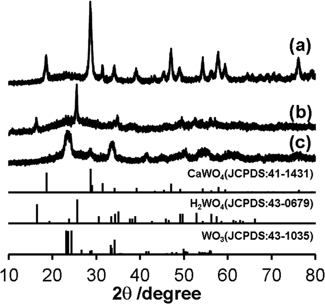 | ||
| Fig. 1 XRD patterns of (a) CaWO4@SiO2, (b) H2WO4@SiO2 and (c) WO3@SiO2. The standard data of CaWO4 (JCPDS: 41-1431), H2WO4 (JCPDS: 43-0679) and WO3 (JCPDS: 43-1035) are shown as a reference. | ||
 | ||
| Fig. 2 TEM images of (a) CaWO4@SiO2, (b) H2WO4@SiO2, (c) WO3@SiO2 and (d) WO3(B). Scale bars are corresponding to 40 nm. Inset of (c) is HRTEM image of WO3@SiO2 and scale bar is corresponding to 5 nm. | ||
The thus-obtained CaWO4@SiO2 powder was treated with aqueous HNO3 solution at 80 °C for 6 h. During HNO3 treatment, the white color of the turbid solution gradually changed to yellow. The corresponding XRD pattern of the thus-obtained yellow powder was assigned to H2WO4 as referred from the JCPDS card (no. 43-0679) (Fig. 1b). The TEM image showed that the core–shell structure was not changed by the HNO3 treatment, as shown in Fig. 2b. These results indicate that the CaWO4 core particle of CaWO4@SiO2 was converted to H2WO4 by the HNO3 treatment and that a core–shell material having an H2WO4 core and a silica shell (H2WO4@SiO2) was obtained.
After calcination of H2WO4@SiO2 at 700 °C, the color changed to light green. The XRD pattern of this sample showed the formation of monoclinic WO3 (JCPDS card no. 43-1035) (Fig. 1c), which was obtained by dehydration of H2WO4. To confirm dehydration of H2WO4, thermogravimetric-differential thermal analysis (TG-DTA) was carried out. The TG-DTA curves of H2WO4@SiO2 were shown in Fig. S2.† A weight loss with endothermic peak was observed at around 100 °C and 200 °C. These are due to desorption of physically adsorbed water molecule on H2WO4@SiO2 particles and coordinated water molecules of H2WO4, respectively. A weight loss of exothermic peak was observed at 250–700 °C, due to combustion of surfactant and siliceous compounds including removal of residual coordinated water.31 A TEM image and high resolution TEM (HRTEM) image of this sample are shown in Fig. 2c and inset of Fig. 2c, respectively. In contrast to the TEM image of H2WO4@SiO2, a hollow space was observed in this sample, indicating the formation of WO3 encapsulated in a hollow silica sphere (WO3@SiO2). The hollow space was caused by shrinkage of the volume as H2WO4 was converted to WO3. The size of the WO3 particles was about 10 nm in diameter, which is smaller than that of the H2WO4 core in H2WO4@SiO2. The lattice fringes of HRTEM image of WO3 particle are assigned to the (100) plane of monoclinic WO3. This is agreement with the XRD result. The silica shell thickness seems to be slightly decreased after the heat treatment. A TEM image of WO3(B) powder that was prepared without using the reverse microemulsion system and silica source showed that the particle size was large and inhomogeneous (40–100 nm) as can be seen in Fig. 2d, although WO3(B) was obtained by the same route as WO3@SiO2 (Fig. S1†). These results suggest that the use of the reverse microemulsion system and the silica shell structure are effective for suppressing the growth of WO3 particles during calcination.
Fig. 3 shows N2 adsorption–desorption isotherms of WO3(B), CaWO4@SiO2 and WO3@SiO2 samples. The isotherm of WO3(B) is classified as characteristic type III according to the IUPAC nomenclature and the BET surface area is 13 m2 g−1, indicating a nonporous structure. The isotherm of CaWO4@SiO2 is classified as characteristic type II and showed a slight increase in N2 uptake at a relative pressure (P/P0) below 0.1, indicating the existence of micropores in the silica shell. The BET surface area of CaWO4@SiO2 was found to be 65 m2 g−1. The isotherm of WO3@SiO2 showed a characteristic type IV with a hysteresis loop and the BET surface area was 175 m2 g−1. Compared with CaWO4@SiO2, WO3@SiO2 showed a steep increase in N2 uptake at P/P0 below 0.1, indicating the formation of a well-developed micropore system probably due to removal of the surfactant in the silica shell during high temperature calcination. Moreover, a hysteresis loop enclosed at a P/P0 of ca. 0.4–0.9 was observed. These phenomena are attributed to the tensile strength effect observed in materials having a hollow structure encapsulated by a pore system of relatively small pore size.32 These results are in agreement with the TEM images and indicate the formation of a hollow structure with a well-developed pore system in the silica shell.
 | ||
| Fig. 3 N2 sorption isotherms of (a) CaWO4@SiO2, (b) WO3@SiO2 and (c) WO3(B). Filled and open circles denote adsorption and desorption isotherms, respectively. | ||
The content of the WO3 component in WO3@SiO2 was estimated by the gravimetric method. The weight of the WO3 component in WO3@SiO2 was measured after etching the SiO2 component by diluted HF aqueous solution; we confirmed in advance that WO3 was not dissolved in the dilute HF aqueous solution. From the measurement, the WO3 content was found to be 60 wt% of WO3@SiO2.
UV/Vis diffuse reflectance spectra of WO3@SiO2 and WO3(B) powders are shown in Fig. 4. Reflectance is converted to absorbance by the Kubelka–Munk equation:
| F(R) = (1 − R)2/2R, | (1) |
| (F(R)hν)1/2 = K(hν − Eg), | (2) |
 | ||
| Fig. 4 UV-visible diffuse reflectance spectrum of (a) WO3@SiO2 and (b) WO3(B). | ||
Photocatalytic decomposition of acetic acid
Photocatalytic decomposition of acetic acid in gaseous phase was used as a measure of photocatalytic activity of WO3 having different morphologies. Since WO3 photocatalysts show poor catalytic activity for decomposition of organic compounds due to their low reduction property, we loaded a Pt co-catalyst on WO3 particles of all of the photocatalysts we examined; these particles are denoted by Pt/WO3.A comparison of time courses of CO2 evolution during decomposition of acetic acid under full-arc irradiation from a 300 W Xe lamp with various Pt-loaded WO3 photocatalysts and TiO2 photocatalyst made of commercially available TiO2 (ST-01, Ishihara Sangyo Co. Ltd.) is shown in Fig. 5. In 100 min, the TiO2 and Pt/WO3@SiO2 photocatalysts produced CO2 continuously to the level of 35 μmol, which corresponds to the stoichiometric amount of the introduced acetic acid (17.5 μmol), indicating complete decomposition of acetic acid. The initial high rate of CO2 evolution with the TiO2 photocatalyst seems to be due to its intrinsically high photocatalytic activity. However, the WO3 photocatalyts (Pt/WO3@SiO2 and Pt/WO3(B)) showed much higher activity than that of the TiO2 photocatalyst, as shown in Fig. 6, suggesting the usefulness of WO3 photocatalysts under visible light conditions. Of the WO3 photocatalyts, Pt/WO3@SiO2 was effective for complete decomposition of acetic acid, as shown in Fig. 5 and 6.
 | ||
| Fig. 5 Time courses for CO2 evolution during photocatalytic decomposition of acetic acid over (a) Pt/WO3@SiO2, (b) Pt/WO3(B), (c) Pt/WO3(B)/SiO2 and (d) TiO2 (ST-01) under full-arc light irradiation from a 300 W Xe lamp. | ||
 | ||
| Fig. 6 Time courses for CO2 evolution during photocatalytic decomposition of acetic acid over (a) Pt/WO3@SiO2, (b) Pt/WO3(B) and (c) TiO2 (ST-01) under visible light irradiation (λ > 400 nm). | ||
In Fig. 5, Pt/WO3@SiO2 and Pt/WO3(B)/SiO2 show concave slopes for CO2 evolution in the initial period. This unique property of the photocatalyts seems to be related to the hollow shell structure. We consider that the release of CO2 from the hollow space of the photocatalysts to the outer space is hindered to some extent by the porous SiO2 shell, leading to the concave slope until the concentration of CO2 reaches a certain level. For the same reason, we can expect that reactive products produced in the hollow space have as higher chance of reaction on the photocatalyst because their escape from the hollow space and supply of acetic acid to the hollow space are hindered by the silica shell. The concentration of the intermediate in the hollow shell of Pt/WO3@SiO2 can be lower than that of Pt/WO3(B) in the gas phase because the intermediate competes with acetic acid for the reaction sites (or photogenerated holes) on WO3. Such a function of the hollow shell (or hollow shell effect) will affect the activity of the photocatalyts as mentioned later.
Pt/WO3@SiO2 and Pt/WO3(B) showed almost the same reaction rates for CO2 evolution during the initial reaction period, as shown in Fig. 5. However, the evolution rate of CO2 with Pt/WO3(B) decreased drastically when the amount of CO2 reached half of the stoichiometric level, suggesting that methanol or formaldehyde, both of which are the chief intermediates for decomposition of acetic acid, accumulates in the system. To confirm this assumption, we added acetic acid to the system with Pt/WO3(B) after the CO2 evolution rate had decreased and we found that the CO2 evolution rate almost recovered to the initial rate (Fig. S3†). This result strongly suggests that the decrease in the CO2 evolution rate with Pt/WO3(B) is not due to poisoning of the active sites of WO3 but is due to the slow decomposition rate of the intermediate. This is also consistent with the fact that CO2 evolution continued even after the CO2 evolution rate had decreased over Pt/WO3(B).
To confirm the effect of the intermediates, products in the gas phase were analyzed during the photocatalytic reaction. As a result, methanol was observed in the gas phase together with very small amounts of methyl formate and methyl acetate. However, formaldehyde was not observed. It is well known that formaldehyde is the major oxidation product from methanol.37 Formaldehyde was not detected in this system probably because formaldehyde was strongly adsorbed on the photocatalysts or decomposed rapidly. The amount of methanol over Pt/WO3@SiO2 was smaller than that over Pt/WO3(B) (Fig. S4†). This result is consistent with the hollow shell effect mentioned above.
In the case of Pt/WO3(B), even after methanol and other intermediates had been completely decomposed, the amount of CO2 was insufficient for a stoichiometric amount, indicating that the formaldehyde produced is strongly adsorbed on Pt/WO3(B). Formaldehyde is easily polymerized to a stable paraformaldehyde at a high concentration as reported in the literature.38,39 Since paraformaldehydes are relatively difficult to decompose, the CO2 evolution rate is drastically reduced if they accumulate on the photocatalyst.
In the case of the hollow space of Pt/WO3@SiO2, however, the sequential photo decomposition reaction of intermediates proceeds efficiently due to the hollow shell effect, which maintains the concentration of formaldehyde at a low level. As a result, formation of paraformaldehyde was probably suppressed and continuous complete decomposition of acetic acid was achieved. The catalytic activity of Pt/WO3(B)/SiO2, which is physically mixed WO3(B) with SiO2, was almost the same as that of Pt/WO3(B). These results indicate that the hollow structure, not the SiO2 content, is important for the complete decomposition of acetic acid. Although further studies are needed to understand the detailed reaction mechanisms, the hollow structure is expected to be effective for the photodecomposition of organic compounds through stable intermediates.
Conclusions
We developed a procedure for the synthesis of WO3 nanoparticles encapsulated in a hollow silica sphere by effectively using a reverse micelle system and volume change of tungsten compounds. The obtained core–hollow shell structure was composed of WO3 nanoparticles of 10 nm in diameter and a porous SiO2 shell of 10 nm in thickness with highly developed micropores. The core–hollow shell structure of Pt-loaded WO3@SiO2 has great advantages in photocatalytic applications, as exemplified by the continuous and complete decomposition of acetic acid, compared to other bulk WO3 photocatalyts. The findings will lead to further improvement in the catalytic activity of WO3@SiO2 by an optimized core–hollow shell structure.Conflicts of interest
There are no conflicts to declare.Acknowledgements
TEM measurement was carried out by using a facility in the Research Center for Ultra-High Voltage Electron Microscopy, Osaka University and TEM observation was supported by Dr Takao Sakata. This research was partially supported by Kansai Research Foundation for Technology Promotion and JSPS KAKENHI Grant Numbers JP15K14127 and JP18K05273.References
- M. R. Hoffmann, S. T. Martin, W. Choi and D. W. Bahnemann, Chem. Rev., 1995, 95, 69 CrossRef CAS.
- A. Fujishima, K. Hashimoto and T. Watanabe, TiO2 Photocatalysis Fundamentals and Applications, BKC, Tokyo, 1999, p. 176 Search PubMed.
- A. Fujishima, T. N. Rao and D. A. Tryk, J. Photochem. Photobiol., C, 2000, 1, 1 CrossRef CAS.
- H. S. Lee, S. M. Koo and J. W. Yoo, J. Ceram. Process. Res., 2012, 13, s300 Search PubMed.
- S. Ikeda, Y. Ikoma, H. Kobayashi, T. Harada, B. Ohtani, T. Torimoto and M. Matsumura, Chem. Commun., 2007, 3753 RSC.
- S. Ikeda, H. Kobayashi, Y. Ikoma, T. Harada, T. Torimoto, B. Ohtani and M. Matsumura, Phys. Chem. Chem. Phys., 2007, 9, 6319 RSC.
- S. Ikeda, H. Kobayashi, T. Sugita, Y. Ikoma, T. Harada and M. Matsumura, Appl. Catal., A, 2009, 363, 216 CrossRef CAS.
- S. Ikeda, H. Kobayashi, Y. Ikoma, T. Harada, S. Yamazaki and M. Matsumura, Appl. Catal., A, 2009, 369, 113 CrossRef CAS.
- W. Zhang, X.-J. Lin, Y.-G. Sun, D.-S. Bin, A.-M. Cao and L.-J. Wan, ACS Appl. Mater. Interfaces, 2015, 7, 27031–27034 CrossRef CAS PubMed.
- Y. Kuwahara, Y. Sumida, K. Fujiwara and H. Yamashita, ChemCatChem, 2016, 8, 2781–2788 CrossRef CAS.
- Y. Yang, X. Liu, X. Li, J. Zhao, S. Bai, J. Liu and Q. Yang, Angew. Chem., Int. Ed., 2012, 51, 9164–9168 CrossRef CAS PubMed.
- T. Umebayashi, T. Yamaki, H. Itoh and K. Asai, J. Phys. Chem. Solids, 2002, 63, 1909–1920 CrossRef CAS.
- N. Murakami, T. Chiyoya, T. Tsubota and T. Ohno, Appl. Catal., A, 2008, 348, 148 CrossRef CAS.
- C. Wang, Z. Chen, H. Jin, C. Cao, J. Lia and Z. Mib, J. Mater. Chem. A, 2014, 2, 17820 RSC.
- V. Moradi, M. B. G. Jun, A. Blackburn and R. A. Herring, Appl. Surf. Sci., 2018, 427, 791 CrossRef CAS.
- R. Asahi, T. Morikawa, T. Ohwaki, K. Aoki and Y. Taga, Science, 2001, 293, 269 CrossRef CAS PubMed.
- G. R. Torres, T. Lindgren, J. Lu, C.-G. Granqvist and S.-E. Lindquist, J. Phys. Chem. B, 2004, 108, 5995 CrossRef CAS.
- H. Irie, Y. Watanabe and K. Hashimoto, J. Phys. Chem. B, 2003, 107, 5483 CrossRef CAS.
- H. Irie, Y. Watanabe and K. Hashimoto, Chem. Lett., 2003, 32, 772 CrossRef CAS.
- T. Ohno, T. Tsubota, K. Nakajima and Z. Miyamoto, Chem. Lett., 2004, 33, 750 CrossRef CAS.
- T. Umebayashi, T. yamaki, S. Tanaka and K. Asai, Chem. Lett., 2003, 32, 330 CrossRef CAS.
- G. Xin, W. Guo and T. Ma, Appl. Surf. Sci., 2009, 256, 165 CrossRef CAS.
- T. Arai, M. Yanagida, Y. Konishi, Y. Iwasaki, H. Sugihara and K. Sayama, Catal. Commun., 2008, 9, 1254 CrossRef CAS.
- T. Arai, M. Horiguchi, M. Yanagida, T. Gunji, H. Sugihara and K. Sayama, Chem. Commun., 2008, 5565 RSC.
- Y. Yin, R. M. Rioux, C. K. Erdonmez, S. Hughes, G. A. Somorjai and A. P. Alivisatos, Science, 2004, 304, 711 CrossRef CAS PubMed.
- T. Harada, S. Ikeda, Y. H. Ng, T. Sakata, H. Mori, T. Torimoto and M. Matsumura, Adv. Funct. Mater., 2008, 18, 2190 CrossRef CAS.
- J. Lee, J. C. Park and H. Song, Adv. Mater., 2008, 20, 1523 CrossRef CAS; J. C. Park, J. U. Bang, J. Lee, C. H. Ko and H. Song, J. Mater. Chem., 2010, 20, 1239 RSC.
- T. Harada, T. Misaka, T. Sakata, S. Ikeda and M. Matsumura, Appl. Mech. Mater., 2013, 372, 132 Search PubMed.
- W. Stöber, A. Fink and E. J. Bohn, J. Colloid Interface Sci., 1968, 26, 62 CrossRef.
- R. Abe, H. Takami, N. Murakami and B. Ohtani, J. Am. Chem. Soc., 2008, 130, 7780 CrossRef CAS PubMed.
- J. Cao, B. Luo, H. Lin, B. Xu and S. Chen, Appl. Catal., B, 2012, 111–112, 288 CrossRef CAS.
- J. C. Groen, L. A. A. Peffer and J. P. Trez-RamRez, Microporous Mesoporous Mater., 2003, 60, 1 CrossRef CAS.
- A. Chithambararaj and A. C. Bose, Beilstein J. Nanotechnol., 2011, 2, 585 CrossRef CAS PubMed.
- M. A. Butler, J. Appl. Phys., 1997, 48, 1914 CrossRef.
- H. Kominami, K. Yabutani, T. Yamamoto, Y. Keraa and B. Ohtani, J. Mater. Chem., 2001, 11, 3222 RSC.
- G. W. Ho, K. J. Chua and D. R. Siow, Chem. Eng. J., 2012, 181– 182, 661 CrossRef.
- M. Kawai, T. Kawai, S. Naito and K. Tamaru, Chem. Phys. Lett., 1984, 110, 58 CrossRef CAS.
- J. L. Davis and M. A. Barteau, J. Am. Chem. Soc., 1989, 111, 1782 CrossRef CAS.
- A. K. Chakraborty, S. Y. Chai and W. I. Lee, Bull. Korean Chem. Soc., 2008, 2, 494 Search PubMed.
Footnote |
| † Electronic supplementary information (ESI) available: XRD patterns of reference samples. TG-DTA curves time courses for CO2 evolution and acetic acid decomposition and methanol production during photocatalytic reaction. See DOI: 10.1039/d0ra01988g |
| This journal is © The Royal Society of Chemistry 2020 |