 Open Access Article
Structural and electronic properties of α-, β-, γ-, and 6,6,18-graphdiyne sheets and nanotubes†
Linwei Lia,
Weiye Qiaob,
Hongcun Baic and
Yuanhe Huang *a
*a
aCollege of Chemistry, Beijing Normal University, Beijing 100875, China. E-mail: yuanhe@bnu.edu.cn
bChemistry and Chemical Engineering College, Xingtai University, Hebei 054001, China
cState Key Laboratory of High-efficiency Utilization of Coal and Green Chemical Engineering, Ningxia University, Ningxia, 750021, China
First published on 29th April 2020
Abstract
α-, β-, γ- and 6,6,18-graphdiyne (GDYs) sheets, as well as the corresponding nanotubes (GDYNTs) are investigated systematically by using the self-consistent-field crystal orbital method. The calculations show that the GDYs and GDYNTs with different structures have different electronic properties. The α-GDY sheet is a conductor, while 2D β-, γ- and 6,6,18-GDYs are semiconductors. The carrier mobilities of β- and γ-GDY sheets in different directions are almost the same, indicating the isotropic transport characteristics. In addition, the electron mobility is in the order of 106 cm2 V−1 s−1 and it is two orders of magnitude larger than the hole mobility of 2D γ-GDY. However, α- and 6,6,18-GDY sheets have anisotropic mobilities, which are different along different directions. For the 1D tubes, the order of stability is γ-GDYNTs > 6,6,18-GDYNTs > β-GDYNTs > α-GDYNTs and is independent of the tube chirality and size. β- and γ-GDYNTs as well as zigzag α- and 6,6,18-GDYNTs are semiconductors with direct bandgaps, while armchair α-GDYNTs are metals, and armchair 6,6,18-GDYNTs change from semiconductors to metals with increasing tube size. The armchair β- and γ-GDYNTs are more favourable to transport holes, while the corresponding zigzag tubes prefer to transport electrons.
1. Introduction
Carbon-based materials such as fullerene (0D),1–3 carbon nanotubes (1D)4,5 and graphene (2D)6,7 have been synthesized and characterized during the last three decades. In recent years, much effort has been focused on another two-dimensional carbon allotrope, graphdiyne (GDY),8 which was first predicted in 1997.9 Graphdiyne is built by inserting diacetylenic linkages into graphene. Depending on the insertion proportions, GDY can be divided into various forms: α-, β-, γ-, and 6,6,18-GDY. In 2010, Li et al. reported the successful preparation of graphdiyne film on the surface of copper, which displayed semiconducting properties.10 γ-GDY nanotube arrays were also synthesized through an anodic aluminium oxide template that was catalysed.11 One-dimensional γ-GDY nanowires12 and nanowalls13 were then synthesized in the following years. In 2017, the β-GDY-containing thin film with a conductivity of 3.47 × 10⁻⁶ S m−1 and a working function of 5.22 eV was successfully synthesized by using a modified Glaser–Hay coupling reaction.14Carbon nanotubes can be constructed by rolling two-dimensional graphene monolayers, and these structures garner enormous interest due to the unique electronic properties resulting from their intrinsic 1D nature.15 Many studies have indicated that the electronic properties of carbon nanotubes sensitively depend on the tube size and chirality. At present, based on the properties of carbon nanotubes, theoretical and experimental researchers have studied the applications of nanotubes in nanoelectronic devices,16 sensors,17 delivery vehicles,18–20 and gas adsorption.21–23 Very recently, atomically precise and controllable graphene origami was realized.24 The chirality and corresponding electronic properties of the as-formed 1D tubular nanostructures on the edges, which resemble nanotubes, were precisely controlled. This research provided a route for fabricating quantum materials and devices.
Previous theoretical studies reported that different graphyne nanotubes (α-, β-, γ-, and 6,6,12-GYNTs) demonstrate diverse electronic properties owing to their complex and volatile geometric configurations.25–28 However, to the best of our knowledge, there are only few studies on γ-GDY nanotubes.29–31 A systematic study on the structural and electronic properties of the four GDYs (α-, β-, γ-, and 6,6,18-GDYs) sheets and their corresponding nanotubes has not been previously reported, which motivate us to undertake the present study. In this work, we employed first-principle calculations to carry out a detailed investigation of these structures, especially focusing on the influence of structures, dimensions, tube chirality and size on the electronic properties and carrier mobilities of these GDYs.
2. Structural properties
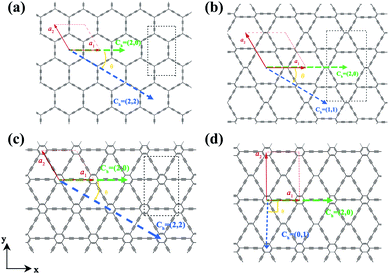
The two-dimensional structures of α-, β-, γ-, and 6,6,18-GDYs are shown in Fig. 1. Their unit cells can be defined by two lattice vectors .29–31 Similar to carbon nanotubes, various graphdiyne nanotubes (GDYNTs) can be generated by rolling the corresponding GDY sheets along the chiral vector
  to make seamless cylinders, represented by (n, m).
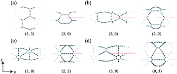
Based on the definitions of the lattice vectors and chiral vectors shown in Fig. 1, armchair and zigzag α-GDYNTs are represented by the (n, n) and (n, 0) chiral indexes, respectively. However, for β- and γ-GDYNTs, (n, 0) is the armchair type and (n, n) is the zigzag type. For 6,6,18-GDYNTs, (n, 0) and (0, n) represent armchair and zigzag tubes, respectively. Namely, armchair and zigzag tubes extend along the x- and y-directions, respectively, for α-GDYNTs but the opposite is the case for β-, γ- and 6,6,18-GDYNTs. Some GDYNTs are shown in Fig. 2 as examples.
3. Theory and methodology
Throughout this study, all the calculations were carried out by means of self-consistent-field crystal (SCF-CO) method based on the Perdew–Burke–Ernzerhof functional for solids (PBEsol),32 which is implemented in the CRYSTAL14 code33,34 to describe the exchange–correlation potential. All of the GDY sheets and GDYNTs were optimized under periodic boundary conditions with the basis set 6-21G*.35 The planar α-, β- and γ-GDYs belong to the P6mm space group and 6,6,18-GDY belongs to the P2mm space group. The symmetry is always maintained during the optimization. The convergence tolerance of the energy is 10−5 hartree, and the maximum allowed gradient and displacement are 0.00045 hartree per bohr and 0.0018 bohr, respectively.To study the transport properties, the carrier mobility (μ) is calculated based on a combination of the deformation potential (DP) theory36 and the effective mass approximation.37 The scattering of charge carriers (electron or hole) by the acoustic phonons is considered. This approach has been widely applied to evaluate the carrier mobilities of various two-dimensional materials (such as β-GY,38 single-layered phosphorus,39,40 germanium monosulfide41 and CaP3![[thin space (1/6-em)]](https://www.rsc.org/images/entities/char_2009.gif) 42) and one-dimensional systems.43–47 The carrier mobility in two-dimensional systems can be expressed as36,48
42) and one-dimensional systems.43–47 The carrier mobility in two-dimensional systems can be expressed as36,48
 | (1) |
Here, kB is the Boltzmann constant, T is the temperature, C is the elastic modulus, m* = ℏ2[∂2ε(k)/∂k2]−1 is the effective mass of the charge carrier, E1 (E1v and E1c) represents the DP constants for the charge carriers (electron and hole). To compute the elastic modulus and the DP constants, we change the lattice of the rectangular cell up to ±0.3% along both the x- and y-directions in Fig. 1 and then calculate the total energy per unit cell and the shift of the valence band maximum (VBM) for holes and the conduction band minimum (CBM) for electrons with respect to the uniaxial strain. The external strain (δ) is defined as δ = (a − a0)/a0, where a and a0 are the strained and equilibrium lattice parameters, respectively. The elastic modulus C for two-dimensional systems is the in-plane stiffness and can be calculated by the equation C = (∂2E/∂δ2)/S0, where E is the total energy per unit cell and S0 is the area at equilibrium for the system. E1 can be defined by E1 = |∂Eedge/∂δ|, where Eedge refers to the VBM and CBM.
For one-dimensional systems, the mobility is given by49
 | (2) |
4. Results and discussion
4.1 Graphdiyne sheets
The calculated lattice parameters are a1 = a2 = 11.45 Å, 14.66 Å and 9.48 Å for α-, β- and γ-GDY sheets, respectively. Moreover, a1 = 9.48 Å and a2 = 13.93 Å for 6,6,18-GDY sheet. These results are close to these in previous works (11.42 Å for α-GDY50 and 9.37–9.48 Å for γ-GDY51–55). The calculated band structures of α-, β-, γ-, and 6,6,18-GDY sheets are shown in Fig. 3. The α-GDY sheet is a conductor with a zero bandgap. The VBM and the CBM are in contact at the K point. α-GDY exhibits a Dirac point similar to the case of graphene.56 β-GDY and γ-GDY are semiconductors with small bandgaps of 0.20 eV and 0.41 eV, respectively. 6,6,18-GDY is a semiconductor with a very narrow bandgap (0.04 eV) at the X′ point. Since the PBE usually underestimates the bandgap, 6,6,18-GDY can still be considered a narrow gap semiconductor. Therefore, the different net structures, which result from the insertion proportion of diacetylenic linkages for these GDYs, lead to different electronic structures and different band shapes. The band structures of the α-, γ- and 6,6,18-GDY sheets here are similar to those obtained by PBE and HSE06.29,31,50,57Now, we calculate the mobilities of the 2D sheets. The rectangular super cells (as shown in Fig. 1) are built for a more intuitive explanation of the transport property. The calculated results are listed in Table 1.
| GDYs | Direction | C | E1c | E1v | μe | μh | ||
|---|---|---|---|---|---|---|---|---|
| α-GDY | x | 100.05 | 0.13 | 0.13 | 3.51 | 0.93 | 6.86 × 10³ | 9.87 × 10⁴ |
| y | 97.53 | 0.68 | 0.65 | 0.98 | 3.52 | 3.15 × 10³ | 2.66 × 10² | |
| β-GDY | x | 130.99 | 0.46 | 0.42 | 0.68 | 4.23 | 1.93 × 10⁴ | 5.81 × 10² |
| y | 133.97 | 0.47 | 0.46 | 0.71 | 4.21 | 1.73 × 10⁴ | 5.11 × 10² | |
| γ-GDY | x | 197.36 | 0.23 | 0.27 | 0.16 | 5.63 | 2.25 × 10⁶ | 1.27 × 10³ |
| y | 201.27 | 0.30 | 0.31 | 0.12 | 5.56 | 2.47 × 10⁶ | 9.53 × 10² | |
| 6,6,18-GDY | x | 140.28 | 0.25 | 0.27 | 4.63 | 0.72 | 1.45 × 10³ | 5.45 × 10⁴ |
| y | 204.26 | 0.28 | 0.29 | 0.52 | 5.67 | 1.41 × 10⁵ | 1.12 × 10³ |
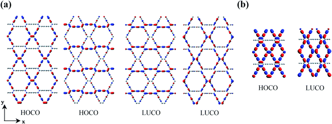
It can be seen from Table 1 that the charge carrier mobilities along the x- and y-directions are very close (μx ≈ μy) for β-GDY and γ-GDY, which indicates the isotropic transport properties. However, the mobilities of the electrons are much higher than those of the holes, and the difference between μe and μh is greater than three orders of magnitude for γ-GDY. Thus, β-GDY and γ-GDY prefer to transport electrons. Table 1 shows that the DP constants for holes (E1v) are more than five times those for electrons (E1c) in the two 2D sheets. The DP constants characterize the coupling strength of the charge carriers with the acoustic phonons. Larger DP constants mean stronger carrier scattering by the acoustic phonons. As already noted that the highest occupied crystal orbitals (HOCOs) have more nodes than the lowest unoccupied crystal orbitals (LUCOs), resulting in the stronger scattering of holes for the 2D γ-GDY.36 The double degenerate HOCOs and LUCOs of β-GDY are shown in Fig. 4a. Along the y-direction, the number of nodes for the HOCOs is more than that for the LUCOs. On the other hand, the number of nodes is the same for both HOCOs and LUCOs along the x-direction. However, the orbitals all spread along the x-direction in the LUCOs but not all in the HOCOs. Therefore, the charge carriers in HOCOs are more prone to be scattered by the acoustic phonons than those in LUCOs. These factors lead to larger DP constants for the holes.
For α-GDY and 6,6,18-GDY, the situations are quite different from those of β-GDY and γ-GDY. Table 1 shows that the mobilities of the charge carriers are anisotropic for both α-GDY and 6,6,18-GDY. For α-GDY, μh(x) is larger than μh(y), and μe(x) is also somewhat larger than μe(y), where the letters in the parentheses denote the direction in which the charge carriers move. Table 1 shows that both the effective mass and DP constant of holes along the y-direction are larger than those along the x-direction for α-GDY, which leads to a relatively lower μh(y). Although E1c(x) ≈ 3.5E1c(y),  . Hence, μe(x) and μe(y) have the same order of magnitude for α-GDY, and the electron mobilities can be considered almost isotropic. In addition, for α-GDY, μe(x) < μh(x) and μe(y) > μh(y). Thus, α-GDY prefers transporting holes along the x-direction, but prefers transporting electrons along the y-direction.
For 6,6,18-GDY, μh(x) > μh(y). This is similar to the case in α-GDY. However, μe(x) < μe(y) for 6,6,18-GDY, which is different from α-GDY. Therefore, 6,6,18-GDY is more favourable to transport holes and electrons along the x- and y-directions, respectively. The difference in carrier mobilities between different directions is mainly due to the difference in the DP constants. The frontier crystal orbitals of 6,6,18-GDY are displayed in Fig. 4b. In the HOCO, the orbitals of sp2 carbons spread along the x-direction, i.e., the orbitals are vertical to the y-direction. This causes the holes to be more easily scattered by the acoustic phonons along the y-direction, leading to E1v(y) > E1v(x), and thus, μh(x) > μh(y) for 6,6,18-GDY. In the LUCO, the spreading direction of sp2 orbitals is precisely opposite of that in the HOCO; thus, E1c(y) < E1c(x), and μe(y) > μe(x). The different spreading directions in the HOCO and LUCO along the x-direction are also the main factor that causes the electrons to be more prone to acoustic phonon scattering than the holes, resulting in E1c(x) > E1v(x) and μe(x) < μh(x). In addition, the LUCO exhibits fewer nodes than the HOCO along the y-direction, leading to E1v(y) > E1c(y). The number of nodes and the orbital spreading direction in the frontier crystals all play important roles in the charge carrier mobilities.
In addition, it can be seen from Table 1 that α-GDY and γ-GDY have the smallest and the largest elastic moduli (C) among these four graphdiynes, respectively. The order of elastic moduli is α-GDY < β-GDY < 6,6,18-GDY < γ-GDY and is precisely opposite to the order of the proportion of the diacetylenic linkages in the system. A larger proportion of the diacetylenic linkages lead to a sparser net structure of carbon atom distribution and a smaller elastic modulus.
The above discussions regarding the GDY sheets show that the different net structures resulting from different proportions of inserted diacetylenic linkages result in different electronic and transport properties, which greatly affects the structure–property relationships of these materials.
4.2 Graphdiyne nanotubes
Rolling a 2D material into a 1D tube is accompanied by strain. The strain energy, which can be used to characterize the stability from 2D sheets to 1D tubes, is defined as the energy difference between the GDYNT and the monolayer GDY sheet. The strain energy per atom Es is calculated by
 | (3) |
The calculated strain energies of the GDYNTs are plotted in the ESI† (Fig. S1). All the strain energies are positive, indicating that none of the GDYNTs is as stable as their corresponding 2D GDY sheets in terms of energy. Es decreases with increasing tube diameter and tends to zero; hence, tubes of larger size are more stable due to their smaller strain. This is similar to the case in many other armchair and zigzag nanotubes, such as the corresponding GYNTs,25–27,58 β-BNyne NT,59 Si-diyne NT60 and ZnO NT.61 However, this trend is in contrast to that observed in γ-GDY43,44 and Si-diyne60 nanoribbons. Therefore, the structures and properties of different 1D materials based on the same 2D sheet are quite different. In addition, it should be pointed out that the stability difference between the armchair and the corresponding zigzag GDYNTs with similar diameters is very small. When the total number of atoms is the same (i.e., n is the same), the armchair α-GDYNT is more stable than the zigzag α-GDYNT, while for the β-GDYNT, γ-GDYNT and 6,6,18-GDYNT, the zigzag nanotube is more stable than the armchair one due to larger diameters.
We also calculated the binding energy per atom (Eb) for all GDYNTs using the expression
 | (4) |
Fig. 5 shows that Eb decreases monotonically with increasing tube diameter and tend to be close to those for the GDY sheets. Moreover, it should be pointed out that the order of Eb is always α-GDYNT > β-GDYNT > 6,6,18-GDYNT > γ-GDYNT regardless of the size or chirality of the GDYNTs when n > 2. The net structures determine the relative stability for the GDYNTs studied. Since the net structures are built by insertion of the diacetylenic linkages, insertion of more diacetylenic linkages reduces the stabilities of the GDY sheets and the corresponding GDYNTs. This is similar to the calculated results of graphyne-like nanotubes.25–27,62
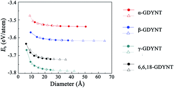 | ||
| Fig. 5 Binding energy per atom as a function of tube diameter. The circles and triangles denote the data for armchair and zigzag GDYNTs, respectively. | ||
To investigate the dynamic stability of the GDYNTs studied here, molecular dynamics (MD) simulations are carried out by means of the density functional-based tight binding (DFTB) method63 with the Atomistix ToolKit 2016.4.45 Here, only the GDYNTs with n = 2 are calculated due to the limitation of our computing conditions. The MD simulations are performed at 300 K, 600 K and 900 K for a total of 3 ps with a time step size of 1 fs. All the structures are well maintained without obvious distortions or collapse even at 900 K after 3 ps, and the changes in the potential energy are less than 0.65%. No sign of crystal instability is observed in these narrowest nanotubes with the MD simulations. Moreover, the phonon spectra for the corresponding GDYTNs are calculated to further confirm the structural stability. The 10 lowest phonon bands for nanotubes with n = 2 are plotted as examples in the ESI† (Fig. S2). No imaginary frequency is detected in these phonon spectra. Therefore, these GDYTNs should be stable structures based on the MD simulations and the calculated phonon spectra. Since the stabilities of these GDYNTs increase as their diameters increase, larger GDYNTs would also be thermodynamically stable structures due to smaller Es and Eb.
The band structures of the GDYNTs are available in the ESI† (Fig. S3). As examples, the band structures of the GDYNTs with n = 4 are shown in Fig. 6. The bandgaps of semiconducting GDYNTs are plotted in Fig. 7 as a function of the tube diameters (Eg–D).
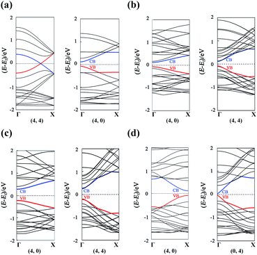 | ||
| Fig. 6 Band structures for (a) α-GDYNTs, (b) β-GDYNTs, (c) γ-GDYNTs and (d) 6,6,18-GDYNTs with n = 4. | ||
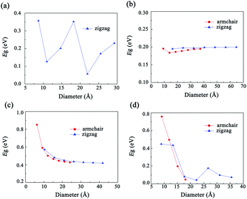 | ||
| Fig. 7 The variation in bandgaps as a function of tube diameter for (a) α-GDYNTs, (b) β-GDYNTs, (c) γ-GDYNTs and (d) 6,6,18-GDYNTs. | ||
It can be seen that α-GDYNTs can be metals or semiconductors depending on the tube chirality. Armchair α-GDYNTs are metals with zero bandgaps, but zigzag α-GDYNTs are semiconductors. Although the α-GDY sheets and armchair α-GDYNTs all have zero bandgaps, the zero bandgap is due to the contact of the CBM and VBM for α-GDY sheets but the crossing of the two frontier bands for the GDYNTs. The two crossed bands are all conduction bands. Moreover, the bandgaps of zigzag α-GDYNTs have oscillatory behaviour with a cycle of 3 (see Fig. 7a). Such oscillatory behaviour has also been observed in the zigzag carbon nanotubes64,65 and the α-graphyne nanotubes.25 Therefore, the electronic structures are changed as the α-GDY transforms from a 2D sheet to the 1D tubes. It seems that α-GDY, α-graphyne62 and graphene66–68 have similar changes in electronic structures from 2D sheets to 1D tubes. This result occurs because the three structures are all composed of hexagonal carbon rings, although the hexagonal carbon rings are different in the three different structures.
Both β-GDYNTs and γ-GDYNTs are semiconductors with direct bandgaps at the Γ point, similar to the cases in the corresponding 2D GDYs. The semi-conductive properties are maintained from the 2D sheet to the 1D tubes for the two GDYs. However, the Eg–D relationships for the two kinds of GDYNTs are different. The bandgaps of the β-GDYNTs are in the range of 0.18–0.20 eV. The changes in the bandgaps are very small (<0.02 eV) with changing tube diameter. A similar phenomenon of a small change in bandgaps also appears in β-GYNTs26 and armchair β-GY nanoribbons.69 However, the bandgaps decrease monotonically with increasing tube diameter for the γ-GDYNTs, which is similar to the results calculated for γ-GDY nanoribbons43,44 and γ-GDYNTs,31 but quite different from the case of γ-GYNTs whose bandgaps oscillate periodically with the parity of the index n.26 These results of β-GDYNTs and γ-GDYNTs reflect the influence of different proportions of inserted diacetylenic linkages on the electronic structures for GDYNTs with different structures. Moreover, the bandgaps of β-GDYNTs and γ-GDYNTs mainly depend on the tube diameters and have little to do with the types of tube chirality.
For 6,6,18-GDYNTs, all zigzag tubes and the armchair tubes with n ≤ 5 are semiconductors, but the armchair tubes can be metals with zero bandgaps when n > 5. Thus, 6,6,18-GDYNTs can be metals or semiconductors. This is somewhat similar to the case of α-GDYNTs. However, the bandgaps do not show oscillatory behaviour with changing tube diameter for the zigzag 6,6,18-GDYNTs. The two smallest tubes (0, 2) and (0, 3) have the largest bandgaps, which should be due to their larger curvatures. The semiconducting armchair 6,6,18-GDYNTs (n ≤ 5) show an Eg–D relationship similar to those γ-GYNTs26 and 6,6,18-GDY nanoribbons.57 Their bandgaps decrease with increasing system size. Armchair 6,6,18-GDYNTs transform from semiconductors into metals as the tube size increases. This is very different from the corresponding armchair 6,6,12-GYNTs, whose number of Dirac points follows the even–odd law.27 Moreover, the position of bandgaps is at the X point for the semiconducting armchair 6,6,18-GDYNTs, while for the zigzag 6,6,18-GDYNTs and the other kinds of semiconducting GDYNTs studied here, the positions are at the Γ point.
To understand the transport properties of these GDYNTs, the charge carrier mobilities of these 1D GDYNTs are calculated. The corresponding results are shown in Fig. 8 and Table S1 in the ESI.†
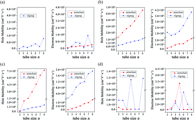 | ||
| Fig. 8 Calculated charge carrier mobilities in (a) α-GDYNTs, (b) β-GDYNTs, (c) γ-GDYNTs and (d) 6,6,18-GDYNTs. | ||
The electron mobilities in metallic armchair α-GDYNTs are on the order of 104 cm2 V−1 s−1. The mobilities of electrons and holes in semiconductive zigzag α-GDYNTs with n > 2 are both on the order of 104–105 cm2 V−1 s−1. Thus, the electron mobilities in the zigzag α-GDYNTs are 1–2 orders of magnitude larger than those for the corresponding 2D α-GDY. The 1D tube structures are more conducive to the transport of electrons than the 2D sheet for α-GDY.
For β-GDYNTs with n > 2, the mobilities of both electrons and holes increase with increasing tube size, but the changes are not larger than one order of magnitude. The mobilities of holes are approximately 105 cm2 V−1 s−1 and one order of magnitude larger than those of electrons for the armchair tubes, but the situation is the opposite for the zigzag tubes. Moreover, the hole mobilities in the armchair tubes are more than one order of magnitude larger than those for the corresponding zigzag tubes, and the situation is the opposite for the electron mobilities. The armchair and zigzag tubes are more conducive to the transport of holes and electrons, respectively. However, the carrier mobilities in the 2D β-GDY sheet are isotropic. The electron mobilities in the 2D β-GDY sheet are on the order of 104 cm2 V−1 s−1 and almost two orders of magnitude larger than the hole mobilities. Therefore, the transport properties of β-GDY are very different in 2D sheet and 1D tubes.
For γ-GDYNTs, the electron mobilities are approximately 102–104 and 106–107 cm2 V−1 s−1, whereas the hole mobilities are 102–105 and 103–104 cm2 V−1 s−1 for the armchair and zigzag types, respectively. Similar to β-GDYNTs, the mobilities increase with increasing tube size for both electrons and holes, which is also similar to the case of γ-GDY nanoribbons.43 Moreover, similar to β-GDYNTs, the armchair tubes prefer to transport holes, but zigzag tubes are more favourable to transport electrons. For the 2D γ-GDY, the mobility is isotropic for the same kind of charge carriers, and the mobilities of electrons are more than three orders of magnitude larger than those of holes. From the 2D sheet to the 1D tubes, the hole mobilities greatly increase especially in the armchair tubes but the electron mobilities change minimally for the zigzag tubes and even decrease for the armchair tubes. These results are somewhat different from the situation for β-GDY, whose change from 2D sheets to 1D tubes increases the mobilities of both electrons and holes.
The carrier mobilities are in the range of 102–107 cm2 V−1 s−1 for the 6,6,18-GDYNTs. The mobilities in the zigzag tubes can reach 106 cm2 V−1 s−1 and experience large fluctuations with increasing tube size. The fluctuation can be as large as 103 cm2 V−1 s−1. The zigzag tubes with higher hole mobilities have lower electron mobilities and vice versa. Moreover, the electron mobilities in semiconducting armchair tubes increase rapidly from 102 to 107 cm2 V−1 s−1 with tube size increasing from n = 2 to n = 5. In addition, the armchair tubes become conductors when n > 5. These results indicate that the tube size (diameter) has a great influence on the transport and electronic properties of the 6,6,18-GDYNTs. These 6,6,18-GDYNTs may be adjusted to be materials more suitable for electron or hole transportation by changing the tube diameter.
It can be seen from the Table S1 in the ESI† that the DP constants are the main factors determining the magnitude of the charge carrier mobilities in β-, γ- and 6,6,18-GDYNTs. It can be seen that in armchair β- and γ-GDYNTs, holes have higher mobilities than electrons because E1v is substantially smaller than E1c. However, E1v > E1c for the zigzag β- and γ-GDYNTs, which leads to higher electron mobilities than hole mobilities. Moreover, E1v < E1c for zigzag 6,6,18-GDYNTs with n = 2, 3, 5, 8, but E1v > E1c for the other zigzag 6,6,18-GDYNTs with n = 4, 6, 7. As mentioned, larger DP constants mean stronger carrier scattering by the acoustic phonons. The HOCO and LUCO of β- and γ-GDYNTs with n = 4 and 6,6,18-GDYNTs with n = 4, 5 are shown as examples in Fig. 9. In armchair β- and γ-GDYNTs with n = 4 and zigzag 6,6,18-GDYNT with n = 5, the spreading direction of the sp2 orbitals in the LUCOs is perpendicular to the tube axis, while the spreading direction is parallel to the tube axis in the HOCOs. As a result, the electrons in the LUCOs experience stronger scattering by the acoustic phonons than the holes in the HOCOs do; thus E1v < E1c. However, for the other five GDYNTs, the spreading situations of the sp2 orbitals are precisely the opposite of the cases discussed above; hence, the holes have stronger scattering than electrons, leading to E1v > E1c. In the frontier orbitals of charge carrier path, the nodes and orbital spreading direction greatly affect the movement of charge carriers.
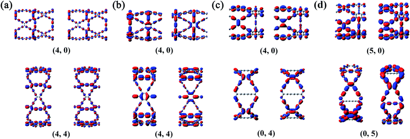 | ||
| Fig. 9 HOCO (left) and LUCO (right) of (a) β-GDYNTs, (b) γ-GDYNTs with n = 4 and 6,6,18-GDYNTs with (c) n = 4 and (d) n = 5. | ||
5. Conclusions
Here, GDY sheets and the corresponding nanotubes are studied theoretically. The PBEsol SCF-CO calculations show that the different structures have different influence on the stability, band structures and transport properties of these systems.α-GDY is a conductor, but β-, γ- and 6,6,18-GDY are semiconductors with direct bandgaps. Zigzag α-GDYNTs are semiconductors with bandgaps oscillating periodically. However, the armchair α-GDYNTs are metals with two frontier bands intersecting at the Fermi level. 6,6,18-GDYNTs may be metals or semiconductors depending on the size of nanotubes. The electronic properties of the γ-GDYTNs can be tuned by tube size due to monotonous decrease of their bandgaps with the increase of tube size.
α-GDY and 6,6,18-GDY sheets have anisotropic transport properties due to the anisotropic carrier mobilities. However, in β-GDY and γ-GDY sheets, the carrier mobilities are isotropic. The electron mobilities are on the order of 104–106 cm2 V−1 s−1, which are much higher than the hole ones. Therefore, these two GDY sheets would be good candidates for transporting electrons.
The order of stability is γ-GDYNTs > 6,6,18-GDYNTs > β-GDYNTs > α-GDYNTs for the 1D tubes, which is independent of the tube chirality and size.
For β- and γ-GDYNTs, the larger the tube size, the higher the carrier mobilities. The calculations show that the carrier mobilities can reach 105–107 cm2 V−1 s−1 in β- and γ-GDYNTs. The armchair β- and γ-GDYNTs are more favourable to transport holes due to their larger hole mobilities, while the zigzag tubes prefer to transport electrons. The crystal orbital analysis shows that the number of nodes in the frontier orbitals and the orbital spreading direction greatly affect the scattering degree of charge carriers, which has an important effect on the mobilities of charge carriers.
Conflicts of interest
There are no conflicts to declare.References
- H. W. Kroto, J. R. Heath, S. C. O'Brien, R. F. Curl and R. E. Smalley, Nature, 1985, 318, 162–163 CrossRef CAS.
- D. M. Guldi, B. M. Illescas, C. M. Atienza, W. Mateusz and M. Nazario, Chem. Soc. Rev., 2009, 38, 1587 RSC.
- T. Braun, A. P. Schubert and R. N. Kostoff, Chem. Rev., 2000, 100, 23–38 CrossRef CAS PubMed.
- T. W. Ebbesen and P. M. Ajayan, Nature, 1992, 358, 220–222 CrossRef CAS.
- P. M. Ajayan, Chem. Rev., 1999, 99, 1787–1800 CrossRef CAS PubMed.
- Y. Zhang, Y. W. Tan, H. L. Stormer and P. Kim, Nature, 2005, 438, 201–204 CrossRef CAS.
- K. Keun Soo, Z. Yue, J. Houk, L. S. Yoon, K. Jong Min, K. S. Kim, A. Jong-Hyun, K. Philip, C. Jae-Young and H. Byung Hee, Nature, 2009, 457, 706–710 CrossRef PubMed.
- X. Gao, H. Liu, D. Wang and J. Zhang, Chem. Soc. Rev., 2019, 48, 908 RSC.
- M. M. Haley, S. C. Brand and J. J. Pak, Angew. Chem., Int. Ed., 1997, 36, 836–838 CrossRef CAS.
- G. X. Li, Y. L. Li, H. B. Li, Y. B. Guo, Y. J. Li and D. B. Zhu, Chem. Commun., 2010, 46, 3256–3258 RSC.
- G. Li, Y. Li, X. Qian, H. Liu and Y. Li, J. Phys. Chem. C, 2011, 115, 2611–2615 CrossRef CAS.
- X. M. Qian, Z. Y. Ning, Y. L. Li, H. B. Li, C. B. Ouyang and Y. J. Li, Dalton Trans., 2011, 41, 730–733 RSC.
- J. Y. Zhou, X. Gao, R. Liu, Z. Q. Xie, J. Yang, S. Q. Zhang, G. M. Zhang, H. B. Liu, Y. L. Li and J. Zhang, J. Am. Chem. Soc., 2015, 137, 7596–7599 CrossRef CAS PubMed.
- J. Li, Z. Xie, Y. Xiong, Z. Li, Q. Huang, S. Zhang, J. Zhou, R. Liu, X. Gao and C. Chen, Adv. Mater., 2017, 29, 1700421 CrossRef PubMed.
- S. Iijima, Nature, 1991, 354, 56–58 CrossRef CAS.
- M. F. L. Volder De, S. H. Tawfick, R. H. Baughman and H. A. John, Science, 2013, 339, 535–539 CrossRef PubMed.
- Y. Wang, Y. Zhi, Z. Hou, X. Dong, L. Wei, S. W. Kong and Y. Zhang, Sens. Actuators, B, 2010, 150, 708–714 CrossRef CAS.
- Y. Li, T. Wang, W. Jing, T. Jiang, C. Gang and S. Wang, Appl. Surf. Sci., 2011, 257, 5663–5670 CrossRef CAS.
- S. K. Vashist, D. Zheng, G. Pastorin, K. Al-Rubeaan, J. H. T. Luong and F. S. Sheu, Carbon, 2011, 49, 4077–4097 CrossRef CAS.
- L. Meng, X. Zhang, Q. Lu, Z. Fei and P. J. Dyson, Biomaterials, 2012, 33, 1689–1698 CrossRef CAS PubMed.
- N. Saikia and R. C. Deka, Struct. Chem., 2014, 25, 593–605 CrossRef CAS.
- A. Soltani, A. V. Moradi and E. T. Lemeski, J. Mol. Struct., 2016, 1105, 128–134 CrossRef CAS.
- M. Watkins, N. Sizochenko, Q. Moore, M. Golebiowski, D. Leszczynska and J. Leszczynski, J. Mol. Model., 2017, 23, 39 CrossRef.
- H. Chen, X. L. Zhang, Y. Y. Zhang, D. Wang, D. L. Bao, Y. Que, W. Xiao, S. Du, M. Ouyang, S. T. Pantelides and H. J. Gao, Science, 2019, 365, 1036 CrossRef CAS PubMed.
- B. Kang and Y. L. Jin, Carbon, 2015, 84, 246–253 CrossRef CAS.
- B. Kang, J. H. Moon and Y. L. Jin, RSC Adv., 2015, 5, 80118–80121 RSC.
- D. C. Yang, R. Jia, Y. Wang, C. P. Kong, J. Wang, Y. Ma, R. I. Eglitis and H. X. Zhang, J. Phys. Chem. C, 2017, 121, 14835–14844 CrossRef CAS.
- H. Zhou, S. Lu, F. Li and Y. Qu, Phys. E, 2016, 78, 19–24 CrossRef CAS.
- S. Jalili, F. Houshmand and J. Schofield, Appl. Phys. A: Solids Surf., 2015, 119, 571–579 CrossRef CAS.
- B. G. Shohany, M. R. Roknabadi and A. Kompany, Phys. E, 2016, 84, 146–151 CrossRef CAS.
- S. Pari, A. Cuéllar and B. M. Wong, J. Phys. Chem. C, 2018, 120, 18871–18877 CrossRef.
- J. P. Perdew, A. Ruzsinszky, G. I. Csonka, O. A. Vydrov, G. E. Scuseria, L. A. Constantin, X. Zhou and K. Burke, Phys. Rev. Lett., 2008, 101, 136406 CrossRef PubMed.
- Y. Noel, P. D'Arco, R. Demichelis, C. M. Zicovich-Wilson and R. Dovesi, J. Comput. Chem., 2010, 31, 855–862 CAS.
- R. Dovesi, R. Orlando, A. Erba, C. M. Zicovich-Wilson, B. Civalleri, S. Casassa, L. Maschio, M. Ferrabone, D. L. P. Marco and P. D'Arco, Int. J. Quantum Chem., 2015, 114, 1287–1317 CrossRef.
- M. Catti, A. Pavese, R. Dovesi and V. R. Saunders, Phys. Rev. B: Condens. Matter Mater. Phys., 1993, 47, 9189–9198 CrossRef CAS PubMed.
- J. Bardeen and W. Shockley, Phys. Rev., 1950, 80, 72–80 CrossRef CAS.
- M. Long, L. Tang, D. Wang, Y. Li and Z. Shuai, ACS Nano, 2011, 5, 2593–2600 CrossRef CAS.
- F. Lin, Y. Huang, C. Shi and Y. Li, J. Solid State Chem., 2018, 265, 402–410 CrossRef CAS.
- G. Schusteritsch, M. Uhrin and C. J. Pickard, Nano Lett., 2016, 16, 2975–2980 CrossRef CAS PubMed.
- J. S. Qiao, X. H. Kong, Z. X. Hu, F. Yang and W. Ji, Nat. Commun., 2014, 5, 4475 CrossRef CAS PubMed.
- F. Li, X. Liu, Y. Wang and Y. Li, J. Mater. Chem. C, 2016, 4, 2155–2159 RSC.
- N. Lu, Z. Zhuo, H. Guo, P. Wu, W. Fa, X. Wu and X. C. Zeng, J. Phys. Chem. Lett., 2018, 9, 1728–1733 CrossRef CAS PubMed.
- H. Bai, Y. Zhu, W. Qiao and Y. Huang, RSC Adv., 2011, 1, 768 RSC.
- L. Li, H. Bai, Y. Li and Y. Huang, Comput. Mater. Sci., 2019, 163, 82–90 CrossRef CAS.
- N. Sa, G. Wang, B. Yin and Y. Huang, Phys. E, 2008, 40, 2396–2399 CrossRef CAS.
- G. Wang and Y. Huang, J. Phys. Chem. Solids, 2008, 69, 2531–2534 CrossRef CAS.
- M. Q. Long, L. Tang, D. Wang, L. Wang and Z. Shuai, J. Am. Chem. Soc., 2009, 131, 17728–17729 CrossRef CAS PubMed.
- J. Dai and X. C. Zeng, Angew. Chem., Int. Ed., 2015, 54, 7572–7576 CrossRef CAS PubMed.
- F. B. Beleznay, F. Bogár and J. Ladik, J. Chem. Phys., 2003, 119, 5690–5695 CrossRef CAS.
- X. Niu, X. Mao, D. Yang, Z. Zhang, M. Si and D. Xue, Nanoscale Res. Lett., 2013, 8, 469 CrossRef.
- Q. Zheng, G. Luo, Q. Liu, R. Quhe, J. Zheng, K. Tang, Z. Gao, S. Nagase and J. Lu, Nanoscale, 2012, 4, 3990–3996 RSC.
- L. D. Pan, L. Z. Zhang, B. Q. Song, S. X. Du and H. J. Gao, Appl. Phys. Lett., 2011, 98, 173102 CrossRef.
- N. Narita and S. Nagai, Phys. Rev. B: Condens. Matter Mater. Phys., 1998, 58, 11009–11014 CrossRef CAS.
- K. Srinivasu and S. K. Ghosh, J. Phys. Chem. C, 2012, 116, 5951–5956 CrossRef CAS.
- M. Long, L. Tang, D. Wang, Y. Li and Z. Shuai, ACS Nano, 2011, 5, 2593–2600 CrossRef CAS PubMed.
- C. N. R. Rao, A. K. Sood, K. S. Subrahmanyam and A. Govindaraj, Angew. Chem., Int. Ed., 2010, 48, 7752–7777 CrossRef PubMed.
- H. Ge, W. Guo and L. Yi, Chem. Phys. Lett., 2015, 633, 30–34 CrossRef CAS.
- A. L. Ivanovskii, Prog. Solid State Chem., 2013, 41, 1–19 CrossRef CAS.
- J. Yun, Y. Zhang, J. Yan, W. Zhao and Z. Zhang, J. Mater. Sci., 2017, 52, 13133–13148 CrossRef CAS.
- Y. Zhu, H. Bai and Y. Huang, J. Phys.: Condens. Matter, 2016, 28, 045303 CrossRef PubMed.
- Y. Zhang, Y.-H. Wen, J.-C. Zheng and Z.-Z. Zhu, Phys. Lett. A, 2010, 374, 2846–2849 CrossRef CAS.
- M. Hu, Y. Jing and X. Zhang, Phys. Rev. B, 2015, 91 Search PubMed.
- M. Elstner, D. Porezag, G. Jungnickel, J. Elsner, M. Haugk, T. Frauenheim, S. Suhai and G. Seifert, Phys. Rev. B: Condens. Matter Mater. Phys., 1998, 58, 7260–7268 CrossRef CAS.
- M. Ouyang, J. L. Huang, C. L. Cheung and C. M. Lieber, Science, 2001, 292, 702–705 CrossRef CAS PubMed.
- Y. Matsuda, J. Tahirkheli and W. A. G. Iii, J. Phys. Chem. Lett., 2010, 1, 2946–2950 CrossRef CAS.
- S. Reich, C. Thomsen and P. Ordejón, Phys. Rev. B, 2002, 65, 155411 CrossRef.
- T. Ando, J. Phys. Soc. Jpn., 2004, 74, 777–817 CrossRef.
- J. C. Charlier and S. Roche, Rev. Mod. Phys., 2007, 79, 677–732 CrossRef CAS.
- H. Ge, G. Wang and Y. Liao, Chem. Phys., 2015, 457, 114–121 CrossRef CAS.
Footnote |
| † Electronic supplementary information (ESI) available. See DOI: 10.1039/d0ra01777a |
| This journal is © The Royal Society of Chemistry 2020 |

