 Open Access Article
Ferroelectric P(VDF-TrFE)/POSS nanocomposite films: compatibility, piezoelectricity, energy harvesting performance, and mechanical and atomic oxygen erosion†
Y. Z. Liu *a,
H. Zhangb,
J. X. Yuc,
Z. Y. Huanga,
C. Wanga and
Y. Suna
aDepartment of Astronautic Science and Mechanics, Harbin Institute of Technology, Harbin, China. E-mail: liuyizhi@hit.edu.com
bSchool of Chemistry and Chemical Engineering, Harbin Institute of Technology, Harbin, China
cSchool of Materials Science and Engineering, Harbin Institute of Technology, Harbin, China
First published on 5th May 2020
Abstract
Poly(vinylidene difluoride) (PVDF) and its copolymers as the polymers with the highest piezoelectric coefficient have been widely used as sensors and generators. However, their relatively low performances limit their applications in some harsh environments. In this work, piezoelectric poly(vinylidene-trifluoroethylene) P(VDF-TrFE) matrices with different amounts of polyhedral oligomeric silsesquioxane (POSS) were prepared by a low temperature solvent evaporation method and thermal poling. The morphology, surface performance, crystalline phase, and piezoelectric and ferroelectric properties of the nanocomposites were investigated and the influence of POSS on these performances was studied. POSS had good compatibility with P(VDF-TrFE) and did not affect the crystalline phase formation of the matrix. The composites presented good piezoelectric properties. Piezo- and triboelectric nanogenerators were designed and fabricated. The voltage and current outputs were analyzed and the polarization effect was evaluated. The average output voltage and the current density of the matrix were 3 V and 0.5 μA cm−2 when subjected to a force of 38 N on an area of 1 cm2. The mechanical properties of P(VDF-TrFE)/POSS nanocomposites were also studied by the nanoindentation test. The hardness and modulus of samples increased 20% and 17% with a low addition of POSS. Atomic oxygen erosion properties of the composites were numerically simulated by the Monte Carlo method. The erosion cavity shape and depth were compared and studied. The influence of POSS addition on the P(VDF-TrFE) matrix and the associated reinforcing mechanism were analyzed.
1. Introduction
Poly(vinylidene fluoride) (PVDF) and its copolymer poly(vinylidene-trifluoroethylene) (P(VDF-TrFE)) have the best piezoelectric properties among polymers and they are widely used in sensors, piezoelectric nanogenerators, smart structure actuators and transducers due to their outstanding piezoelectric performances in the field of polymers.1–9 Meanwhile, PVDF can be fabricated into a soft and thin device which can be coated onto other structures. Compared with the alternative piezoelectric ceramics, PVDF can also be mixed with several additive materials with good compatibility. These special advantages ensure that PVDF and its copolymers can be used as sensors and actuators in the field of aerospace engineering. PVDF as a thin dust detector sensor has been widely used in harsh environments.10,11 It has been already confirmed that neat piezoelectric polymers cannot completely meet the mechanical, thermal and atomic oxygen erosion requirements in the harsh space environment.12,13 The incorporation of inorganic or organic nanofillers into the PVDF matrix is a good method to improve these performances.Polyhedral oligomeric silsesquioxane (POSS) can enhance the degradation resistance of the matrix in complex environments such as high atomic oxygen,14,15 bacterial16 and high humidity conditions.17 POSS is a unique class of organic–inorganic hybrid nanomaterial with the formula (RSiO1.5)n. Given its unique reinforcing performance, composites with POSS as a nanofiller have been extensively studied in recent years.18–21 The inorganic POSS core cage structure with Si–O bonds and optional organic chains, can enhance matrix performances such as thermal stability,22 mechanical strength,23 micropore volume,24 atomic oxygen resistance properties25 and oxidation resistance.21,26 Unlike other inorganic materials, POSS retains excellent compatibility with matrix at the micro scale. In this work, fluoropropyl POSS (POSS) was incorporated into the matrix. Fluoropropyl POSS and P(VDF-TrFE) are theoretically miscible because of the electrostatic interactions and the polar C–F bonds in their molecules.
Researches of P(VDF-TrFE) in hybrid composite used as touch sensors, energy storage devices, and field-effect transistors have been widely studied in recent years.27–30 Nah et al.31 fabricated and reported the ultrathin P(VDF-TrFE) nanofiber air filter that can be activated by the dipoles polarization to enhance the filtering efficiency. The electrically activated P(VDF-TrFE) filter demonstrates that the filtering efficiencies were over 88% after polarization and 94% after triboelectrification. Liu et al.32 added graphene into P(VDF-TrFE) by the solution casting method. When the additions of graphene were low, there was no effect on the crystallinity degree and open-circuit voltage of the composites increased. Wei et al.29 demonstrated the stretching induced alignment method to achieve highly oriented electrospun P(VDF-TrFE). The aligned P(VDF-TrFE) produced a high average output voltage to monitor body gestures, for the development of motion tracking technology.
To our knowledge, this is the first report on fabrication and performances of P(VDF-TrFE)/POSS hybrid nanocomposite. In this study, different additions of fluoropropyl POSS were added into a P(VDF-TrFE) matrix by a low temperature solvent evaporation method and thermal poling was employed to produce the piezoelectric effect. The morphology, crystalline phase, surface performance, piezoelectric and ferroelectric properties of nanocomposites were investigated and the influence of POSS on these performances was studied. Piezo- and triboelectric nanogenerators were fabricated. Meanwhile, the voltage and current outputs of nanogenerators were analyzed respectively and the polarization effect was evaluated. Some mechanical properties of P(VDF-TrFE)/POSS nanocomposites including hardness, elastic modulus and contact stiffness were also studied. Besides the experimental tests above, a numerical simulation strategy was employed to study the atomic oxygen erosion of the composites based on the Monte Carlo method.
2. Experimental
2.1. P(VDF-TrFE)/POSS composite preparation
P(VDF-TrFE) (65 wt%/35 wt%) was purchased from Solvay Solexis. Fluoropropyl POSS (code. FL0578; (3,3,3-trifluoropropyl)8Si8O12; Fig. S1†) as nanofiller was purchased from Hybrid Plastics (Hattiesburg, USA). N,N-Dimethyl formamide (DMF; 99%) was purchased from Aldrich Chemical Co.P(VDF-TrFE) and composites were prepared by a low temperature solvent evaporation method. P(VDF-TrFE) and different additions of POSS were dissolved in DMF solvent at 70 wt% by stirring at 50 °C for 4 h. The dissolved solution was drop-casted onto an ITO glass and the evaporation was subsequently carried out at 80 °C for 1 h to remove the solvent. The prepared sample was annealed at 120 °C for 2 h. The mass ratios of POSS additions were 0, 3, 5, and 8%. Nanocomposites with different POSS contents were denoted as POSSn-P(VDF-TrFE) (n = 3, 5, and 8, respectively). The target thickness of composite samples was 40 μm and the composite films appeared to be uniform by a visual check.
2.2. Polarization process and piezoelectric nanogenerator preparation
To obtain the piezoelectric property or fabricate the piezoelectric nanogenerator, the sample was gold coated on both sides then poled at 100 °C. The effective polarization time was set to 2 h. Poling was achieved by applying an electric field of 40–120 MV m−1 between parallel plates. The dipole can be arrayed and the polarization property can be obtained by high voltage.33,34 The preparation process of P(VDF-TrFE) and POSS piezoelectric composite is shown in Fig. S1.†2.3. Triboelectric nanogenerator preparation
The triboelectric nanogenerator consisted of two layers, i.e. P(VDF-TrFE) and aluminum films. The poled and nonpoled P(VDF-TrFE) films were covered by the gold electrode (thickness = 40 nm, area = 10 × 10 mm) on one side. The gold electrode and aluminum film were placed on the opposite side. The two layers were separated by four 2 mm spacers (3 m VHB tape). The schematic diagram is shown in Fig. S2.†2.4. Characterization
The morphologies of the P(VDF-TrFE) and the composites were characterized using a field-emission scanning electron microscope (FESEM, JEOL 7600F). The accelerating voltage was set to 5.0 kV. Contact angle was measured by a video-based optical contact angle measuring system (Dataphysics OCA15 Pro) with droplets of 6 μL. The crystalline phase of the samples was recorded by an X-ray diffractometer (Shimadzu). The piezoelectric response (d33) of samples was measured with the standard static piezoelectric constant measuring instrument. The driving electric field was applied by use of Radiant Ferroelectric Premier Equipments, which contained Radiant Precision High Voltage Interface and Precision Premier II. The value of hysteresis period was 10 ms. The thickness of the films was measured by a profilometer (Dektak Stylus Profilometer). A magnetic shaker (Sinocera, Model JZK-20) was employed to apply the dynamic mechanical pressure and the frequency was set to 5 Hz. The mechanical pressure was applied using two force gauges (Model M7-025 and Model CY-YD-303). The low-noise current pre-amplifier (Stanford Research System, Model SR570) and the oscilloscope were used to measure the voltage and the current outputs respectively. The G200 Nano Indenter (Agilent Technologies) was employed to test the hardness and elastic modulus of the samples. The maximum value of displacement was 2000 nm and altogether eight specimens were tested to get accurate results. The test was based on the method of ‘G-Series Hardness and Modulus via Displacement Control’. The temperature was kept at 20 °C and the relative humidity was 30%. The loading speed was kept as a constant force rate per second.2.5. Atomic oxygen erosion simulation based on Monte Carlo model
The atomic oxygen erosion of P(VDF-TrFE) (65 wt%/35 wt%) with different additions of POSS composites was simulated by the Monte Carlo method. The structure of PVDF contains two C–H bonds in one repeat unit. For P(VDF-TrFE), one C–H bonds of PVDF in the repeat unit is replaced by one C–F bonds. The assumptions, the empirical equations and the parameters used in the simulation were based on in-spaceflight tests and long duration exposure facility (LDEF) from NASA.35,36 Based on the experimental results of these tests, several physical assumptions and modeling processes have been proposed in these works.37,38 The program was compiled by Matlab to simulate the interaction of protected materials with atomic oxygen. The related primary parameters, equation and atomic oxygen fluence were also shown in ESI.†3. Results and discussion
3.1. SEM analysis and contact angle
All samples are translucent and flexible, and the filler cannot be observed on the surface of samples. The SEM images of P(VDF-TrFE) with 0, 3, 5, and 8 wt% of POSS are shown in Fig. 1. The image of neat P(VDF-TrFE) showed typical fiber characteristics. With the addition of POSS, the characteristic shape decreased. When POSS content was low, it had good compatibility with the matrix. Compatibility as an important indicator could imply the uniformity of the composite material. Good compatibility indicated the composite maintained the basic performances of the matrix, especially mechanical property. It can also ensure the performances of samples in use do not change significantly. Increasing POSS content was accompanied by the agglomeration phenomenon becoming gradually obvious. Compared with traditional inorganic fillers such as silicon dioxide, several kinds of POSS can be chosen to improve various special properties of the matrix including the thermal protection and self-healing of the matrix.39–41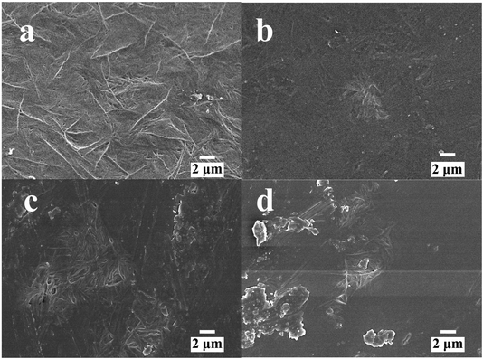 | ||
| Fig. 1 The SEM images of P(VDF-TrFE) and POSS composites (a) P(VDF-TrFE), (b) POSS3-P(VDF-TrFE), (c) POSS5-P(VDF-TrFE), (d) POSS8-P(VDF-TrFE). | ||
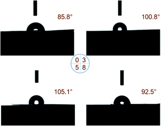
The contact angle of water with P(VDF-TrFE) with different additions of POSS is shown as Fig. 2. A small amount of POSS enhances the hydrophobic property of P(VDF-TrFE) matrix but the contact angle falls when more POSS is added. POSS used in this work was fluoropropyl POSS, which belonged to fluorinated POSS. Fluorinated POSS could modify the surface property and enhance the hydrophobic property especially for FD POSS (heptadecafluorodecyl POSS) which was the most hydrophobic crystalline solid material known.42
Fluoropropyl POSS containing the flexible organic fluoropropyl chains and the rigid inorganic Si–O core cage was chosen to incorporate into P(VDF-TrFE) matrix. Si and O atoms were generated symmetrically along the four-fold inversion axis and part of the organic group bonded to Si had perfect ordering.43,44 The bond interactions and molecular arrangement determined the surface property, including hydrophobicity.
3.2. Crystalline phase analysis
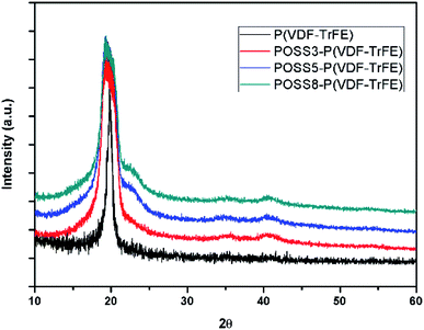
The XRD patterns of P(VDF-TrFE) and the composites with different POSS additions are shown in Fig. 3. As seen in this figure, neat PVDF and all composites exhibit major crystalline peaks at 2θ = 20.3° which are attributed to the β phase. All the composites showed a minor diffraction peak at 40.8°, which correspond to (111)/(201) lattice planes of the β form crystallites.30,45 It can be seen that the additions of POSS broaden the diffraction peaks. It can be shown that the mean crystallite size will decrease. Similar result was obtained by Achaby.46 This may be that some small crystallites form when POSS were added.3.3. Piezoelectric property
The piezoelectric constants of P(VDF-TrFE) samples with different POSS additions in different electric fields are shown in Fig. 4. Four samples at four different positions were tested to establish variability in the results. The piezoelectric effects can be obtained even at very low electric field and the samples were not stretched. The piezoelectric properties enhanced with the increase of polarization intensity. When the electric field exceeded 70 MV m−1, the piezoelectric effect enhanced remarkably. Subsequently, with the increase of electric field, the change was no longer obvious. When the value of electric field reached 140 MV m−1, it was difficult to polarize and electric discharge phenomenon appeared. The piezoelectric effect did not decrease obviously with the additions of POSS, especially for 3 wt%. The d33 constant of 3 wt% addition of POSS was nearly equivalent to the one of neat P(VDF-TrFE). A small amount of POSS addition did not prevent the dipole from rotation and the large aggregation did not appear which resulted in discharging.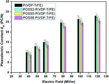 | ||
| Fig. 4 The piezoelectric constants of P(VDF-TrFE) and POSS composites applied by different electric fields. | ||
The more details of the polarization process were as follows: the sample was put into the silicone oil and firstly polarized at a high temperature of 100 °C. Poling was achieved by applying an electric field of 40–120 MV m−1. After two hours later, the heating device was turned off whereas the voltage was maintained until environment temperature reduced to room temperature. This cooling time was set at 20 minutes. There existed a value of the high temperature polarization time. When the time of high temperature polarization reached a certain degree, the dipole rotated fully under the electric field. After that very period, the piezoelectric effect did not increase significantly over extended time. Meanwhile, the temperature was reduced to room temperature and high electric field was maintained during this process. The aim was to make the dipoles rotate sufficiently so that they were no longer disordered. The piezoelectric constants (d33) of the sample were 10% higher than that of the sample without this process. More importantly, as time went by in later use, the loss of piezoelectric effect of samples with this process was very insignificant. For example in our test, after 70 storage days, the d33 reduced from 24.7 to 24.3. However, the loss of piezoelectric effect without this process existed. This was because that dipoles can rotate and disorder again under high environmental temperature when high temperature polarization was off. The sample was poled by a high electric field with cooling the silicone oil to room temperature, which can make the dipoles array orderly, so that the piezoelectric effect can be maintained at room temperature.
3.4. Ferroelectric properties
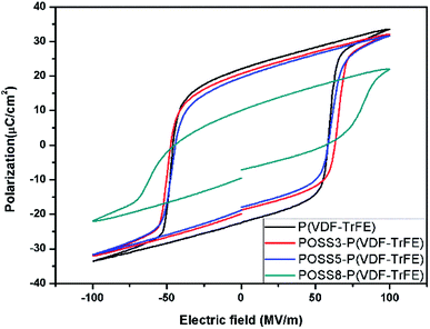
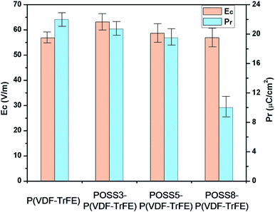
The ferroelectric hysteresis loops and relative properties of P(VDF-TrFE) with different additions of POSS are shown in Fig. 5 and 6, respectively. P(VDF-TrFE) possessed the larger remnant polarization (Pr) and the less coercive field (Ec) compared with PVDF9. From aspects of the remnant polarization for P(VDF-TrFE), the coercive field value of all samples showed smaller variations. The influence of POSS on the coercive field was not obvious. The addition of POSS cannot affect the coercive force remarkably and the dipoles can rotate freely under the eternal electric field.The loops were not significantly different in shape when the addition was less than 5%, showing that the similar switching behavior existed for these samples. The remnant polarization of the composite decreased constantly with the increase of the POSS addition. Especially when the addition exceeded 8%, the remnant polarization decreased remarkably. The saturation loop of the composite with the addition of 8% POSS was difficult to obtain before discharging. With the large increase of POSS, the contents of polar substance and the available switching dipoles decreased, so the remnant polarization value decreased. Combined with d33 result, it can be seen that the high voltage induced the reorientation of the molecular chain with the movement of polar molecules. The polarization switching was exhibited when the electric field was reversed and the piezoelectric response generated obviously. The large homogeneous regions appeared because of the dipolar moments orientation under the electric field. The typical characteristic as a ferroelectric composite appeared.
3.5. Piezo and triboelectric nanogenerator and polarization effect
The properties of poled composite piezoelectric nanogenerators were also studied. All piezoelectric nanogenerators were fabricated by depositing the electrodes on both sides of the film and poling at 80 MV m−1. All piezoelectric nanogenerators were subjected to a force of 38 N on the area of 1 cm2 at a frequency of 5 Hz as shown in Fig. 7. The average output voltage and the current density of matrix were 3 V and 0.5 μA cm−2 respectively. With the low additions of POSS, the average output voltage and the current density were almost the same. When the addition was 8%, the relative electric properties reduced remarkably. The PVDF bimorph was also fabricated and the electric properties of the poled PVDF film were studied in previous work,47 and an average output voltage of 2.8 V and a current density of 100 nA cm2 were generated. Compared with PVDF, the electric property values of P(VDF-TrFE) were higher. Parida et al.7 presented the poled compact P(VDF-TrFE) piezoelectric nanogenerator, and the voltage output was 4 V and the current was 0.6 μA cm−2 under the pressure was 0.63 MPa. Chen et al.48 prepared a flexible piezoelectric sensor using the P(VDF-TrFE) film and micropillars prepared by imprinting mold, and output voltages under a vertical force of 2 N were 0.2 V and 0.6 V respectively.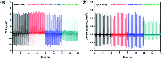 | ||
| Fig. 7 (a) Voltage output and (b) current density from P(VDF-TrFE)/POSS composites piezoelectric generator subjected to a pressure of 38 N at a frequency of 5 Hz. | ||
The force-electric signal of non-poled P(VDF-TrFE) piezoelectric nanogenerator was almost undetectable. The triboelectric nanogenerator consisting of P(VDF-TrFE) and the aluminum film was fabricated to evaluate the effect of the polarization process on electrical properties. The P(VDF-TrFE) triboelectric nanogenerators were applied by the force of 38 N (area = 10 × 10 mm, 5 Hz). The voltage output and current density from P(VDF-TrFE) triboelectric generator are shown in Fig. 8. From the results, the electric properties enhanced obviously after poling. Compared with the non-poled samples, the voltage and the current of the poled samples increased remarkably under the same force excitation. The polar β phase can be generated by low temperature solvent evaporation or drawing the α stable phase films, and the polarization effect can be generated by poling. The molecular chain reorientation can be induced orderly along the direction of the electric field and the all-trans planar zigzag molecular configuration was generated.39,40
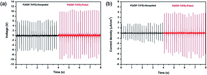 | ||
| Fig. 8 (a) Voltage output and (b) current density from P(VDF-TrFE) triboelectric generator subjected to a pressure of 38 N at a frequency of 5 Hz. | ||
The available switching dipoles and electric properties in the sample increased due to increasing ferroelectric all-trans planar zigzag molecular configuration. When the force was applied, the molecular dipoles aligned and the dipole density changed. The piezoelectric potential of the poled samples generated more strongly compared with the non-poled samples. The free-charge carriers moved from the negative potential to the positive potential region to balance the electric potential and a positive voltage peak was produced.
Fig. 9 shows the lighted LEDs of the composite TENG. Under the periodical external force, all 27 LEDs are lighted up with high brightness. It's also easy to identify every lighted LED even though it's not dark outside.
3.6. Mechanical properties
The typical load-unload testing of P(VDF-TrFE) with different additions of POSS is shown in Fig. 10. The hardness and elastic modulus data are listed in Table 1. The Berkovich indenter tip was used and the distance between nanoindentation test points was more than ten times that of indenter radius to eliminate the mutual interference. The nanoindentation depth was set 2000 nm and the load duration 10 s due to the viscoelasticity of polymers.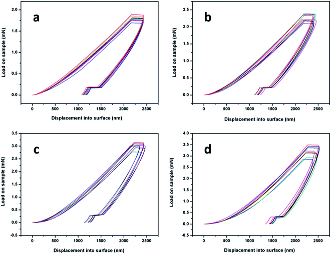 | ||
| Fig. 10 The nanoindentation test via displacement control of P(VDF-TrFE) and POSS with (a) 0, (b) 3 wt%, (c) 5 wt%, (d) 8 wt%. | ||
| H (GPa) | E (GPa) | S (105 N m−1) | |
|---|---|---|---|
| P(VDF-TrFE) | 0.045 ± 0.003 | 1.52 ± 0.18 | 1.035 ± 0.013 |
| POSS3-P(VDF-TrFE) | 0.051 ± 0.005 | 1.78 ± 0.28 | 1.187 ± 0.017 |
| POSS5-P(VDF-TrFE) | 0.059 ± 0.006 | 1.91 ± 0.31 | 1.268 ± 0.022 |
| POSS8-P(VDF-TrFE) | 0.060 ± 0.008 | 1.97 ± 0.42 | 1.330 ± 0.028 |
From the results, the hardness and modulus of samples enhanced with increasing additions of POSS. The mechanical properties can be increased due to the rigid Si–O nanocage. Meanwhile, the deviations of the test results also reflected the compatibility of materials, as shown in Table 1. Additional of POSS content would increase the clustering effect to some extent and the deviations of test results became larger. The shape of the unloading curve was determined by the elastic recovery process in the indentation area, which can be regarded as pure elasticity. The slope of the unloading curve was expressed as contact stiffness. The variation trend of contact stiffness was the same as that of modulus and hardness of samples.
The mechanical tests showed the samples possessed outstanding flexibility. The stiffness could indirectly reflect the flexibility of materials and the additions of POSS increased the contact stiffness but not remarkably. The corresponding error values also implied that the composites were uniformly distributed and no obvious local clusters appeared, which could cause a large error. Compared with other traditional fillers, POSS with inorganic nanocage and organic group could guarantee both the compatibility between matrix and filler and the flexibility of material.
3.7. Atomic oxygen erosion simulation
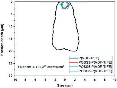
According to eqn (1), (2) and (4),† the simulated atomic oxygen number of P(VDF-TrFE) was less than that of PVDF in the same atomic oxygen fluence. The emitter was placed 1 μm above a 2 μm-wide crack of the protective coating, and atomic oxygen could not react with the protective coating. The average atomic oxygen arrival angle was 0°.The erosion cavity shape of P(VDF-TrFE) is shown in Fig. 11. The atomic oxygen erosion effect on P(VDF-TrFE) was obvious and the cavity depth size was about 19 μm. The beaker shape appeared on the P(VDF-TrFE) with a protective coating after the erosion, which was narrow at the top and jagged and wide at the bottom. Only very few works focused on atomic oxygen erosion effect on some polymers used in space from NASA report were performed.35,49,50 The research about other polymers was helpful to that of P(VDF-TrFE). The erosion yield of Kapton was 3.0 × 10⁻²¹ mm3 per atom, higher than that of PVDF. It meant the erosion effect would be more obvious at the same atom fluence value. Huang studied atomic oxygen erosion effect on Kapton by the Monte Carlo method. The cavity depth was 40 μm under almost the same oxygen fluence. Banks37 studied the erosion effect on Kapton using the Monte Carlo method and LDEF tests. In this work, the Maxwell–Boltzmann distribution was employed to set the ejected atoms velocity and the negative normal direction was set as the average arrival direction. The initial erosion part mainly distributed along the centerline perpendicular to the protective coating crack. As the depth increases, more atomic oxygen particles impacted on each side and thus the cavity became broader. The bottom would also form the jagged undercut rather than a tip or a circular shape. The cavity shape was similar to the results from in-spaceflight and LDEF tests. It was also able to say that the Monte Carlo method could be used to simulate atomic oxygen erosion with protective coating properly. In our previous work, the erosion depth of PVDF by the Monte Carlo method was studied. The erosion depth of PVDF was deeper than that of P(VDF-TrFE). For P(VDF-TrFE), the C–H bonds of PVDF in the repeat unit are replaced by C–F bonds in proportion. The C–F bond broke with greater difficultly during the atomic oxygen erosion. The simulated atomic oxygen number of P(VDF-TrFE) was less than that of PVDF in the same atomic oxygen fluence. So P(VDF-TrFE) has a better atomic oxygen resistance effect than PVDF according to the simulation.
The atomic oxygen resistance of POSS was due to the Si–O cage, and the Si–O bond (8 eV) is strong enough to withstand the atomic oxygen erosion (4.5 eV).10,25 Heat reaction would not occur between the composite and atomic oxygen as POSS absorbed the impact energy derived from atomic oxygen.51 Therefore, the interaction between POSS and atomic oxygen was not taken into account in the simulation. Based on some ref. 37, 52 and 53, the erosion yields for 3%, 5% and 8% POSS/P(VDF-TrFE) were λ = 1.09 × 10⁻²² mm3 per atom, λ = 0.99 × 10⁻²² cm3 per atom and λ = 0.83 × 10⁻²² cm3 per atom respectively.
The erosion profile curves of P(VDF-TrFE) with 3%, 5% and 8% POSS additions at atomic oxygen fluence value of 4.1 × 10²⁰ atoms per cm2 were also shown in Fig. 11. With the increase additions of POSS, the erosion effect was dramatically reduced, which meant that POSS could enhance atomic oxygen erosion resistance of the composite remarkably even with small content. The cavity profile appeared to be randomly distributed rather than “beaker shaped”. The Si–O core of POSS could resist the atomic oxygen erosion and no heat reaction happened, so the erosion yield of composites reduced with the additions of POSS. Meanwhile, the unique structure of POSS absorbed the impact energy of atomic oxygen. Combined with studies of other researches, it is a good way to incorporate POSS into the matrix to obtain good overall properties of the composite including compatibility, thermal, electric, mechanical properties and erosion resistance.
4. Conclusion
In this work, piezoelectric nanocomposites consisted of 0, 3, 5, 8 wt% of POSS and P(VDF-TrFE) matrix were prepared by solvent evaporation method and thermal poling.The morphology, surface performance, crystalline phase, piezoelectric and ferroelectric properties of nanocomposites were investigated and the influence of POSS on these performances was studied. POSS as a nanofiller had good compatibility with P(VDF-TrFE). All samples exhibited β phase by low temperature solvent evaporation and POSS did not affect the crystalline phase formation of matrix. POSS with fluoropropyl group can enhance the hydrophobic property of P(VDF-TrFE) matrix. The piezoelectric effects can be obtained even if the electric field was very low and the samples were not stretched. When the electric field exceeded 70 MV m−1, the piezoelectric effect enhanced remarkably. The piezoelectric effect did not decrease obviously with the additions of POSS, especially for 3 wt%. The polarization effect was maintained for a long time by using the proper poling method. Ferroelectric performance results showed that similar switching behavior existed for these composites. The coercive field value of all samples showed smaller variations. The influence of POSS on the coercive field was not obvious.
Piezo and triboelectric nanogenerators were designed and fabricated. The voltage and current output were analyzed and the polarization effect was evaluated. With low additions of POSS, the average output voltage and the current density were nearly the same as the unfilled material. The voltage and the current of the poled samples increased remarkably under the same force excitation. The high output is used as a power source for lighting LEDs.
The mechanical properties of P(VDF-TrFE)/POSS nanocomposites were also studied by the nanoindentation test. The hardness, modulus and contact stiffness of samples enhanced with increasing additions of POSS. The increase of mechanical properties was due to the rigid Si–O nanocage. Compared with other inorganic filler, POSS can guarantee the flexibility and the compatibility between matrix and filler.
Atomic oxygen erosion property of the composites was also simulated by the Monte Carlo method. The cavity shape and depth were compared and studied. The cavity depths reduced with the additions of POSS. POSS can increase erosion resistance due to the Si–O nanocage.
Conflicts of interest
The authors declare no conflict of interest.Acknowledgements
The authors thank professor John Summerscales (University of Plymouth) and professor PooiSee Lee, Miss X. R. Zhou, Dr Kaushik Parida, Dr Jiaqing Xiong and Dr Peng Cui (School of Materials Science and Engineering, Nanyang Technological University, Singapore) for helpful discussion. The authors thank National Natural Science Foundation of China (11602073) and Natural Science Foundation of Heilongjiang Province of China (QC2018005), and the research is also supported by “the Fundamental Research Funds for the Central Universities” (Grant No. HIT.NSRIF.201821) and the State Scholarship Fund (201706125076) from China Scholarship Council.References
- J. H. Lee, H. J. Yoon, T. Y. Kim, M. K. Gupta, J. H. Lee, W. Seung, H. Ryu and S. W. Kim, Adv. Funct. Mater., 2015, 25, 3203–3209 CrossRef CAS
.
- F. R. Fan, W. Tang and Z. L. Wang, Adv. Mater., 2016, 28, 4283–4305 CrossRef CAS PubMed
.
- X. Xue, P. Deng, S. Yuan, Y. Nie, B. He, L. Xing and Y. Zhang, Energy Environ. Sci., 2013, 6, 2615–2620 RSC
.
- B. Chu, X. Zhou, K. Ren, B. Neese, M. Lin, Q. Wang, F. Bauer and Q. Zhang, Science, 2006, 313, 334 CrossRef CAS PubMed
.
- N. R. Alluri, B. Saravanakumar and S.-J. Kim, ACS Appl. Mater. Interfaces, 2015, 7, 9831–9840 CrossRef CAS PubMed
.
- Y. Cho, J. B. Park, B.-S. Kim, J. Lee, W.-K. Hong, I.-K. Park, J. E. Jang, J. I. Sohn, S. Cha and J. M. Kim, Nano Energy, 2015, 16, 524–532 CrossRef CAS
.
- K. Parida, V. Bhavanasi, V. Kumar, R. Bendi and P. S. Lee, Nano Res., 2017, 10, 3557–3570 CrossRef CAS
.
- K. Parida, V. Bhavanasi, V. Kumar, J. Wang and P. S. Lee, J. Power Sources, 2017, 342, 70–78 CrossRef CAS
.
- Y. Liu, Y. Sun, F. Zeng and Y. Chen, Int. J. Electrochem. Sci., 2013, 8, 5688–5697 CAS
.
- T. K. Minton, M. E. Wright, S. J. Tomczak, S. A. Marquez, L. Shen, A. L. Brunsvold, R. Cooper, J. Zhang, V. Vij, A. J. Guenthner and B. J. Petteys, ACS Appl. Mater. Interfaces, 2011, 4, 492–502 CrossRef PubMed
.
- O. Mori, H. Sawada, R. Funase, T. Endo, M. Morimoto, T. Yamamoto, Y. Tsuda, Y. Kawakatsu and J. i. Kawaguchi, Proceedings of 21st International Symposium on Space Flight Dynamics, ISSFD 2009, Citeseer, 2009 Search PubMed
.
- R. I. Gonzalez, S. H. Phillips and G. B. Hoflund, J. Appl. Polym. Sci., 2004, 92, 1977–1983 CrossRef CAS
.
- E. Grossman and I. Gouzman, Nucl. Instrum. Methods Phys. Res., Sect. B, 2003, 208, 48–57 CrossRef CAS
.
- X. Wang, Y. Li, Y. Qian, H. Qi, J. Li and J. Sun, Adv. Mater., 2018, 30, 1803854 CrossRef PubMed
.
- Y. Z. Liu, Y. Sun, F. L. Zeng, Q. H. Zhang and L. Geng, Appl. Surf. Sci., 2014, 320, 908–913 CrossRef CAS
.
- M. Wu, B. Ma, T. Pan, S. Chen and J. Sun, Adv. Funct. Mater., 2016, 26, 569–576 CrossRef CAS
.
- Y. Zi, L. Lin, J. Wang, S. Wang, J. Chen, X. Fan, P.-K. Yang, F. Yi and Z. L. Wang, Adv. Mater., 2015, 27, 2340–2347 CrossRef CAS PubMed
.
- H. Liu, Y. Wang, J. Huang, Z. Chen, G. Chen and Y. Lai, Adv. Funct. Mater., 2018, 28, 1707415 CrossRef
.
- W. Zhang, G. Camino and R. Yang, Prog. Polym. Sci., 2017, 67, 77–125 CrossRef CAS
.
- Y.-X. Zhu, H.-R. Jia, Z. Chen and F.-G. Wu, Nanoscale, 2017, 9, 12874–12884 RSC
.
- Y. R. Liu, Y. D. Huang and L. Liu, Compos. Sci. Technol., 2007, 67, 2864–2876 CrossRef CAS
.
- X. Yang, L. Tang, Y. Guo, C. Liang, Q. Zhang, K. Kou and J. Gu, Composites, Part A, 2017, 101, 237–242 CrossRef CAS
.
- Z. Ren, J. Nie, J. Shao, Q. Lai, L. Wang, J. Chen, X. Chen and Z. L. Wang, Adv. Funct. Mater., 2018, 28, 1802989 CrossRef
.
- S. Kataoka, Y. Kamimura and A. Endo, Langmuir, 2018, 34, 4166–4172 CrossRef CAS PubMed
.
- S. Duo, M. Song, T. Liu, C. Hu and M. Li, J. Nanosci. Nanotechnol., 2013, 13, 1356–1359 CrossRef CAS PubMed
.
- A. Fina, D. Tabuani, F. Carniato, A. Frache, E. Boccaleri and G. Camino, Thermochim. Acta, 2006, 440, 36–42 CrossRef CAS
.
- V. Bhavanasi, V. Kumar, K. Parida, J. Wang and P. S. Lee, ACS Appl. Mater. Interfaces, 2016, 8, 521–529 CrossRef CAS PubMed
.
- X. Chen, K. Parida, J. Wang, J. Xiong, M.-F. Lin, J. Shao and P. S. Lee, ACS Appl. Mater. Interfaces, 2017, 9, 42200–42209 CrossRef CAS PubMed
.
- S. Ma, T. Ye, T. Zhang, Z. Wang, K. Li, M. Chen, J. Zhang, Z. Wang, S. Ramakrishna and L. Wei, Adv. Mater. Technol., 2018, 3, 1800033 CrossRef
.
- V. Bhavanasi, D. Y. Kusuma and P. S. Lee, Adv. Energy Mater., 2014, 4, 1400723 CrossRef
.
- K. S. Han, S. Lee, M. Kim, P. Park, M. H. Lee and J. Nah, Adv. Funct. Mater., 2019, 29, 1903633 CrossRef
.
- L. Wu, M. Jing, Y. Liu, H. Ning, X. Liu, S. Liu, L. Lin, N. Hu and L. Liu, Composites, Part B, 2019, 164, 703–709 CrossRef CAS
.
- J. Gomes, J. S. Nunes, V. Sencadas and S. Lanceros-Mendez, Smart Mater. Struct., 2010, 19, 065010 CrossRef
.
- B. B. Tian, J. L. Wang, S. Fusil, Y. Liu, X. L. Zhao, S. Sun, H. Shen, T. Lin, J. L. Sun, C. G. Duan, M. Bibes, A. Barthélémy, B. Dkhil, V. Garcia, X. J. Meng and J. H. Chu, Nat. Commun., 2016, 7, 11502 CrossRef CAS PubMed
.
- B. A. Banks, K. K. de Groh and S. K. Miller, Materials Research Society Symposium Proceedings, Cambridge Univ. Press, 2004 Search PubMed
.
- K. K. de Groh and B. A. Banks, Proceedings of the International Symposium on Materials in a Space Environment (ISMSE-11), 2009 Search PubMed
.
- B. Banks, Monte Carlo modeling of atomic oxygen attack of polymers with protective coatings on LDEF, National Aeronautics and Space Administration, USA, 1993, pp. 1137–1150 Search PubMed
.
- B. A. Banks, J. A. Backus, M. V. Manno, D. L. Waters, K. C. Cameron and K. K. de Groh, Proceedings of the ISMSE-11, 2009, vol. 15, p. 18 Search PubMed
.
- J. Boček, L. Matějka, V. Mentlík, P. Trnka and M. Šlouf, Eur. Polym. J., 2011, 47, 861–872 CrossRef
.
- K. Tanaka and Y. Chujo, J. Mater. Chem., 2012, 22, 1733–1746 RSC
.
- S. Song, M. Cao, H. Shan, C. Du and B. Li, Mater. Des., 2018, 156, 242–251 CrossRef CAS
.
- J. M. Mabry, A. Vij, S. T. Iacono and B. D. Viers, Angew. Chem., 2008, 120, 4205–4208 CrossRef
.
- S. T. Iacono, A. Vij, W. Grabow, D. W. Smith Jr and J. M. Mabry, Chem. Commun., 2007, 4992–4994 RSC
.
- S. M. Ramirez, Y. J. Diaz, R. Campos, R. L. Stone, T. S. Haddad and J. M. Mabry, J. Am. Chem. Soc., 2011, 133, 20084–20087 CrossRef CAS PubMed
.
- F. He, M. Sarkar, S. Lau, J. Fan and L. H. Chan, Polym. Test., 2011, 30, 436–441 CrossRef CAS
.
- M. El Achaby, F. Z. Arrakhiz, S. Vaudreuil, E. M. Essassi and A. Qaiss, Appl. Surf. Sci., 2012, 258, 7668–7677 CrossRef CAS
.
- Y. Z. Liu, Z. W. Hao, J. X. Yu, X. R. Zhou, P. S. Lee, Y. Sun, Z. C. Mu and F. L. Zeng, Smart Mater. Struct., 2019, 28, 055011 CrossRef CAS
.
- X. Chen, J. Shao, H. Tian, X. Li, Y. Tian and C. Wang, Smart Mater. Struct., 2018, 25018 CrossRef
.
- K. K. de Groh, B. A. Banks, C. McCarthy, L. Berger, L. Roberts and R. Rucker, Proceedings of the 10 th ISMSE, 8 th ICPMSE: 19-23 June, 2006 Search PubMed
.
- K. deGroh, B. A. Banks, C. E. McCarthy, R. N. Rucker, L. M. Roberts and L. A. Berger, NASA/TM-2006-214482, E-15774, 2006 Search PubMed
.
- Z. Xu, Y. Zhao, X. Wang and T. Lin, Chem. Commun., 2013, 49, 6755–6757 RSC
.
- R. L. Gonzalez, S. J. Tomczak, G. B. Hoflund, T. K. Minton and A. Brunsvold, DTIC Document, 2002 Search PubMed
.
- K. K. de Groh, B. A. Banks, J. A. Dever, D. A. Jaworske, S. K. Miller, E. Sechkar and S. R. Panko, NASA Tech. Memo., 2008, 215482 Search PubMed
.
Footnote |
| † Electronic supplementary information (ESI) available. See DOI: 10.1039/d0ra01769h |
| This journal is © The Royal Society of Chemistry 2020 |

