DOI:
10.1039/D0RA01483D
(Paper)
RSC Adv., 2020,
10, 15530-15540
Developing an effective polarizable bond method for small molecules with application to optimized molecular docking†
Received
15th February 2020
, Accepted 31st March 2020
First published on 20th April 2020
Abstract
Electrostatic interaction plays an essential role in protein–ligand binding. Due to the polarization effect, electrostatic interactions are largely impacted by their local environments. However, traditional force fields use fixed point charge–charge interactions to describe electrostatic interactions but is unable to include the polarization effect. The lack of the polarization effect in the force field representation can result in substantial error in biomolecular studies, such as molecular dynamics and molecular docking. Docking programs usually employ traditional force fields to estimate the binding energy between a ligand and a protein for pose selection or scoring. The intermolecular interaction energy mainly consists of van der Waals and electrostatic interaction in the force field representation. In the current study, we developed an Effective Polarizable Bond (EPB) method for small organic molecules and applied this EPB method to optimize protein–ligand docking in computational tests for a variety of protein–ligand systems. We tested the method on a set of 38 cocrystallized structures taken from the Protein Data Bank (PDB) and found that the maximum error was reduced from 7.98 Å to 2.03 Å when using EPB Dock, providing strong evidence that the use of EPB charges is important. We found that our optimized docking approach with EPB charges could improve the docking performance, sometimes dramatically, and the maximum error was reduced from 12.88 Å to 1.57 Å in Optimized Docking (in the case of 1fqx). The average RMSD decreased from 2.83 Å to 1.85 Å. Further investigations showed that the use of the EBP method could enhance intermolecular hydrogen bonding, which is a major contributing factor to improved docking performance. Developed tools for the calculation of the polarized ligand charge from a protein–ligand complex structure with the EPB method are freely available on GitHub (https://github.com/Xundrug/EPB).
Introduction
Virtual screening1–11 (VS), also known as in silico screening, is a widely used approach to screen small molecule databases to find putative active compounds for a specific target. Compared to experimental screening12–14 methods, VS is much faster and cost-efficient. There are two types of virtual screening methods: ligand-based15–19 and structure-based10,20–26 VS. For the ligand-based VS methods, 2D or 3D chemical similarity analysis is usually used to scan the compound library against known active compounds. For the structure-based VS methods, molecular docking and scoring is usually applied to evaluate whether a compound can fit well with the binding site of a target.
Since structure-based virtual screening methods play a critical role in early drug discovery, many efforts have been made to improve the docking and scoring methods. There are many docking software packages available,27 including GLIDE,28,29 FlexX,30–32 Gold,33–35 Dock,36 ICM,37 and Autodock.38–41 These docking programs usually apply empirical force fields or scoring functions to evaluate the binding affinity between a protein and ligand. Thus, the performance of these docking programs is largely impacted by the accuracy of the force fields42–45 used in the docking process. Electrostatic interaction plays an essential role in the protein–ligand binding process.46,47 Traditional molecular force fields use fixed charge interactions to model electrostatic interactions between atom pairs. Polar interactions between molecules are largely impacted by their local environment. The polarization of polar groups contributes a lot to the electrostatic interaction energy. The lack of a polarization effect is one major drawback of traditional molecular force fields.
Electrostatic interactions play an important role in determining the structure and function of biomolecules.48–53 Therefore, an accurate description of electrostatic interactions is essential for the description of protein dynamics and for the structure–function correlation studies of proteins. In the past few decades, significant progress has been made in the development of molecular mechanics (MM) force fields for biomolecular simulation.54–59 However, the main drawback of standard force fields is the lack of polarization effects. In 1976, Warshel and Levitt60 considered the protein polarization effect within the QM/MM method. Since then, many attempts have been made to develop molecular models that bring protein polarization effects into standard force fields,55,61–63 such as the fluctuating charge model,62–74 Drude oscillator,75–77 induced multipole,78–82 and hybrid QM/MM,83 to represent the electronic polarization. The similarities and differences between these methods have been commented on and explained in a number of papers.84–86 We have worked to develop an efficient method, termed the effective polarizable bond87 (EPB), to treat the polarization effect for protein dynamics simulation over the past several years. The EPB method has shown good performance in studying protein–protein binding and protein folding simulation in previous studies.88,89
Several groups have tried to include the polarization effect in the molecular docking process. Hensen et al.90 introduced the QM/MM approach to protein–ligand interaction energy calculation and found that the polarization effect can contribute as much as one-third of the total electrostatic interaction energy. Cho et al.91–93 developed a QM-polarized ligand docking (QPLD) method, which combines Schrodinger's docking program Glide28,29 and the QM/MM module QSite.94,95 Bikadi and Hazai96 applied the PM6 semi-empirical quantum-mechanical partial charge to the redocking test using AutoDock38 4 software and found that the docking accuracy was significantly increased. Chaskar et al.97 developed a QM/MM scoring function with a semiempirical self-consistent charge density functional tight-binding method and CHARMM force field and found that the QM/MM scoring yielded a substantially improved success.
We developed an efficient effective polarizable bond87 (EPB) method to treat the polarization effect for protein dynamics simulation over the past several years. The EPB method is an effective fluctuation charge model in which all polar groups98 in proteins are polarizable. The polarizable parameters for each polar bond are pre-determined by quantum chemical calculation of the model molecules under varying electrostatic environments. The EPB method has shown good performance in studying protein–protein binding and protein folding simulation in previous studies.88,89 In the current study, we extended the EPB method to derive the EPB parameters for small drug-like molecules and applied the EPB method in an optimized protein–ligand docking study.
The remaining of the article is organized as follows. The Method section gives a brief overview of the EPB method, the derivation of the polarizable bond parameters for small organic molecules, and the optimized molecular docking details. The Result and discussion section presents the performance of the optimized docking results in the computational experiments. The final section concludes the current study.
Methods
Brief description of the EPB method
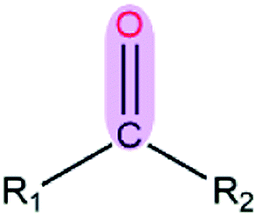
The current EPB model only considers polar groups in proteins and allows atomic charges of these polar groups to fluctuate according to their local electrostatic environment. Here, we give a brief description of the EPB model, while a more detailed description can be found in previous publications.87,98 For example, if we transfer a polar group CO from the gas phase to the liquid phase, the energy of the system can be written as:| | |
E = Eele + Ep-cost = [qCΦC + qOΦO] + κ(μliquid − μgas)2
| (1.1) |
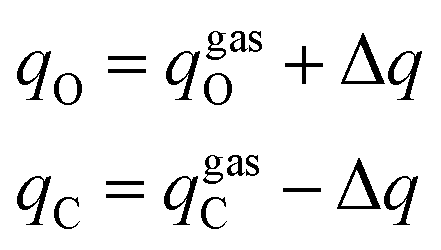
where Eele is the interaction energy between the molecule and the external electric field and Ep-cost represents the polarization cost energy, qC and qO are the ESP charges of the C and O atoms, ΦC and ΦO are the electrostatic potentials at the C and O atoms, 1/κ is the polarizability of the CO group, and μliquid and μgas are the dipole moment of the CO group in the liquid and gas phase. In the CO group, if the charge transferred from atom O to atom C is Δq, the final charges of C and O atoms and the dipole moment change along the CO bond in this process are given by:| |
 | (1.2) |
| | |
Δμ = μliquid − μgas = Δq × dCO
| (1.3) |
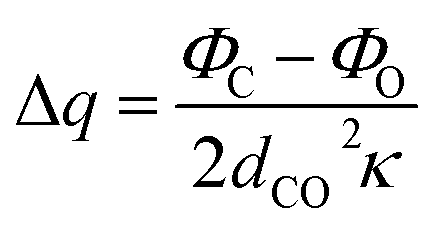
where dCO is the CO bond. Combining eqn (1.1)–(1.3) and minimizing the total electrostatic energy with respect to the variation of Δq, the charge transfer and energy can be written as:| |
 | (1.4) |
| |
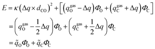 | (1.5) |
where ![[q with combining tilde]](https://www.rsc.org/images/entities/i_char_0071_0303.gif) C and O are the effective charges of C and O atoms, and the polarization parameter κ for each polar bond is predetermined from quantum chemistry calculations using appropriate molecular models,87 and we can get the polarization cost energy as a function of the polarization state (as shown in Fig. 1).
C and O are the effective charges of C and O atoms, and the polarization parameter κ for each polar bond is predetermined from quantum chemistry calculations using appropriate molecular models,87 and we can get the polarization cost energy as a function of the polarization state (as shown in Fig. 1).
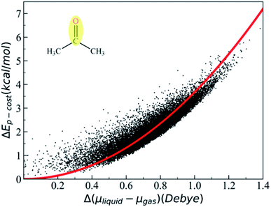 |
| | Fig. 1 Polarization cost energy as a function of the change of the dipole moment. The black points represent data of the CO group, which was fitted to the quadratic curve colored red. Polarizable bond parameters for small organic molecules. | |
In the current work, we extended the EPB method to include small organic molecules. First, we identified all common polar groups in small organic molecules and designed corresponding model molecules to represent these polar groups. Next, quantum mechanical calculations were performed to derive the polarizable parameters κ for each polar bond using model molecules and ESP (electrostatic potential) charges were then used to fit the polarizable parameters κ.
Sampling of the molecular configurations by MD simulations
First of all, we needed to select appropriate molecular models (Fig. S1–S13†). For example, if we wanted to derive the polarizable parameter for the –CO group (see Fig. 2), we used acetone as one of the molecular models. At first, the simulation was performed with the AMBER14 package and the Leap module was used to add hydrogen atoms. After that, the model molecule was placed in an octahedron TIP3P water model with the distance from the surfaces of the box to the closest protein atoms set to 10 Å. The periodic boundary condition and the particle mesh Ewald99 method were employed to treat long-range electrostatic effects.100 The energy minimization was performed for the system without any constraints. After minimization, the system was heated from 0 K to 300 K in 500 ps, and then 5 ns NPT MD simulation was performed at 300 K. After equilibration, a 30 ns production run was performed. For the MD simulation, the integration time step was set to 1 fs and Langevin dynamics101 was employed to regulate the temperature with the collision frequency set to 2 ps−1. Besides, the SHAKE algorithm102 was applied to all of the covalent bonds involving hydrogen atoms during the MD simulations.
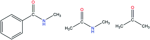 |
| | Fig. 2 Three molecular models containing a carbonyl group. | |
Quantum chemistry calculation of the molecular polarization
After the MD simulation, 15![[thin space (1/6-em)]](https://www.rsc.org/images/entities/char_2009.gif) 000 configurations were selected for quantum chemistry calculation. For each configuration, the quantum chemistry calculation of acetone was performed with or without the electric field generated by the background charge of water molecules. Then, we could obtain the polarization cost energy as a function of the polarization state (shown in Fig. 1). By fitting the data points in Fig. 1, we could derive an average polarizable parameter for the CO group. The DFT103,104 method (M06/6-31G**)105 in Gaussian 09 (ref. 106) was used for quantum chemical energy calculation and AMBER14 (ref. 107) software was used for the MD simulation. The EPB polarizable parameters for some representative polar bonds are listed in Table 1.
000 configurations were selected for quantum chemistry calculation. For each configuration, the quantum chemistry calculation of acetone was performed with or without the electric field generated by the background charge of water molecules. Then, we could obtain the polarization cost energy as a function of the polarization state (shown in Fig. 1). By fitting the data points in Fig. 1, we could derive an average polarizable parameter for the CO group. The DFT103,104 method (M06/6-31G**)105 in Gaussian 09 (ref. 106) was used for quantum chemical energy calculation and AMBER14 (ref. 107) software was used for the MD simulation. The EPB polarizable parameters for some representative polar bonds are listed in Table 1.
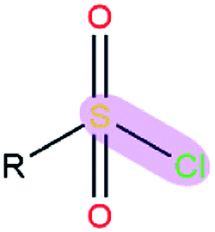
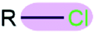
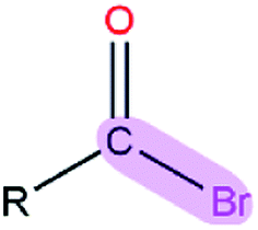
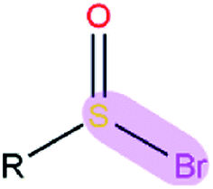
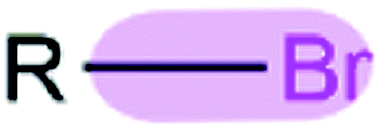
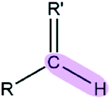
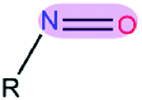
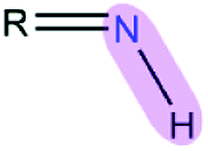
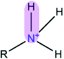
Table 1 EPB parameters for selected polar groupsa
| Polar bond |
κ/(kcal mol−1debye−2) |
d/(Å) |
| The polarizable parameter κ is in kcal mol−1 debye−2 and the bond length d is in Å. |
 |
R = aryl |
1.28 |
1.16 |
| R = alkyl |
3.11 |
1.16 |
 |
R = aryl |
4.72 |
1.35 |
| R = alkyl |
5.63 |
1.33 |
 |
1.43 |
1.81 |
 |
1.38 |
2.12 |
 |
1.36 |
2.11 |
 |
R = aryl |
1.38 |
1.72 |
| R = alkyl |
1.78 |
1.78 |
 |
1.18 |
1.99 |
 |
1.09 |
2.36 |
 |
1.06 |
2.37 |
 |
R = aryl |
1.00 |
1.90 |
| R = alkyl |
1.33 |
1.99 |
 |
R = aryl |
3.04 |
1.23 |
| R = alkyl |
3.98 |
1.23 |
 |
3.51 |
1.23 |
 |
1.17 |
1.66 |
 |
R′ = O, S, N |
6.35 |
1.09 |
| R′ = others |
4.14 |
1.09 |
 |
3.49 |
1.21 |
 |
6.82 |
1.01 |
 |
10.05 |
1.01 |
 |
6.74 |
1.01 |
 |
8.83 |
1.01 |
 |
3.80 |
1.22 |
 |
7.74 |
0.94 |
 |
R = aryl |
9.15 |
0.94 |
| R = alkyl |
10.97 |
0.95 |
 |
R = aryl |
2.85 |
1.34 |
| R = alkyl |
3.29 |
1.34 |
 |
2.44 |
1.53 |
 |
3.07 |
1.47 |
 |
3.92 |
1.47 |
Optimized docking approach
Glide28,29 software was employed to perform molecular docking in the present work. The final ligand pose in Glide is primarily determined by the total intermolecular electrostatic and van der Waals energy. In Glide, the electrostatic energy is screened by a distance-dependent dielectric constant. If we change atomic charges used to calculate the electrostatic interaction energy in molecular docking, the final ligand pose would also change. We chose some co-crystal structures as a test set in our optimized docking experiment. All the test cases were downloaded from the Protein Data Bank108 (PDB) and structural waters were deleted. The raw PDB files usually contain some missing atoms, missing residues, or missing loop regions. In order to make these structures suitable for the modeling tasks, we used the Protein Preparation Wizard to prepare the protein structures. The force field used for the docking process was the OPLS_2005 force field, which was available to us to use. To test the performance of the polarized EPB charge in the docking, we replaced the ligand charge with the EPB charge and kept the other parameters unchanged in OPLS_2005. The protein was kept fixed during the docking process while the ligand was flexible. We calculated the root mean square derivation (RMSD) between the final docking pose and the original ligand geometry from the raw PDB files (the reference structure) as an indicator for performance evaluation.
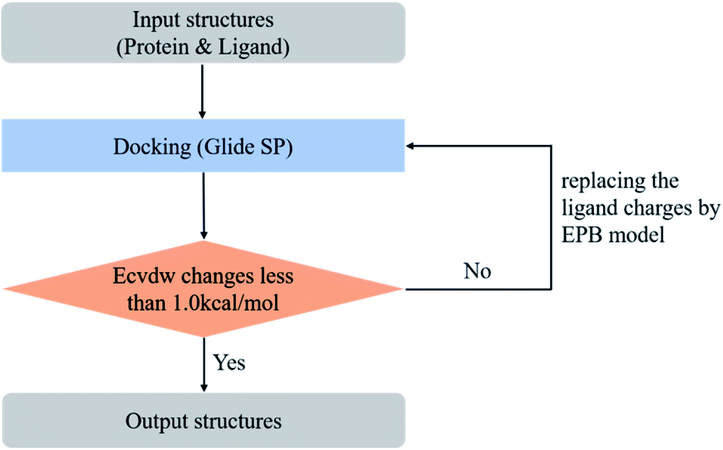
However, in practical virtual screening tasks, we had no prior knowledge of the native binding mode. Thus, we could not generate proper EPB charges before docking. We solved this problem by performing docking and EPB charge calculation iteratively (optimized docking). The iterative procedure can be described as follows: (1) dock the ligand to the protein with the original OPLS_2005 force field. (2) Select the top scoring pose and derive the EPB charges of the ligand using the EPB method. (3) Dock the ligand to the protein with the polarized EPB charge derived in step 2. (4) Repeat steps (2) and (3) until the changes of Ecvdw (which is the non-bonded interaction energy between the ligand and the receptor, including the van der Waals and Coulomb interaction) drop below 1.0 kcal mol−1 (see Fig. 3). A test set consisting of 80 co-crystal structures was used for optimized docking assessment. There was no metal ion or covalent bond between the ligand and protein and all water molecules were deleted.
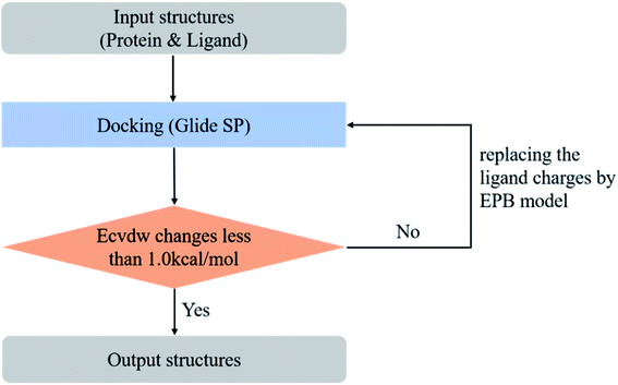 |
| | Fig. 3 Workflow of the optimized (iterative) docking procedure using the EPB method. | |
Result and discussion
Validation of the EPB charges for docking
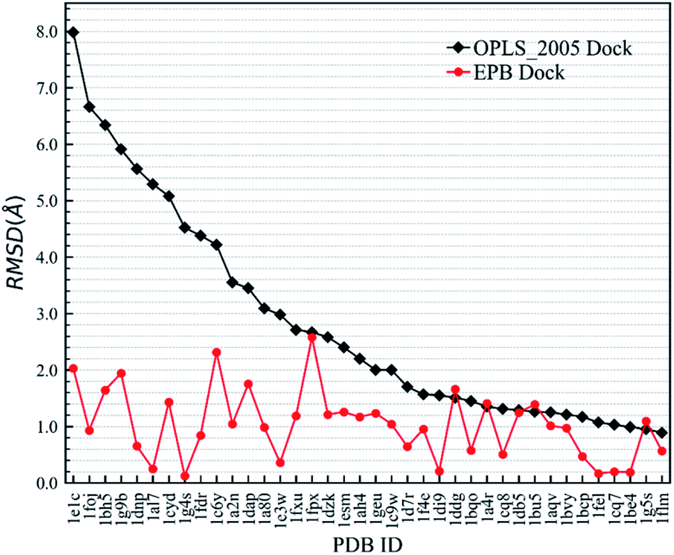
First, we needed to validate the above-described protocol for optimized docking. The polarized charges derived from the protein–ligand co-crystal structure were helpful during the docking test. We chose a test set composed of 38 protein–ligand co-crystal structures. Two different docking methods were performed for comparison: the regular docking procedure using the OPLS_2005 force field (OPLS_2005 Dock) and docking with EPB charges derived from the co-crystal structure (EPB Dock). The ligand atomic charges were calculated by the EPB method, while the charges of the protein atoms were fixed (OPLS_2005 force field). The docked structure with the lowest nonbonded binding energy (screened electrostatic energy and van der Waals energy between the ligand and protein, termed Ecvdw in Glide) was used to determine the final ligand pose. The root mean square derivation (RMSD) between the docking pose and the ligand coordinates from the co-crystal structure was calculated to assess the docking performance. Table 2 lists the Ecvdw and RMSD values for each docking method. From Table 2, we can observe that the Ecvdw value derived from EPB docking is lower than that from docking with OPLS_2005 force field. This was mainly due to the fact that the polarizable charges in EPB docking enhance the electrostatic interaction between the ligand and protein. Fig. 4 shows the RMSD changes from OPLS_2005 Dock to EPB Dock. We can find that the docking poses derived from EPB Dock are much better. In some cases, the EPB Dock method yielded obvious improvements compared to the OPLS_2005 Dock results. The maximum error was reduced from 7.98 Å to 2.03 Å when using EPB Dock.
Table 2 Validation study results for 38 randomly selected complexes
| PDBID |
OPLS_2005 Dock |
EPB Dock |
| Ecvdw/(kcal mol−1) |
RMSD/(Å) |
Ecvdw/(kcal mol−1) |
RMSD/(Å) |
| 1e1c |
−70.9 |
7.98 ± 3.65 |
−92.7 |
2.03 ± 0.71 |
| 1foj |
−24.4 |
6.66 ± 2.72 |
−87.0 |
0.93 ± 0.07 |
| 1bh5 |
−49.9 |
6.34 ± 2.49 |
−65.2 |
1.64 ± 0.43 |
| 1g9b |
−39.7 |
5.91 ± 2.19 |
−58.8 |
1.94 ± 0.64 |
| 1dnp |
−88.5 |
5.56 ± 1.94 |
−96.5 |
0.65 ± 0.27 |
| 1al7 |
−30.7 |
5.29 ± 1.75 |
−64.9 |
0.25 ± 0.55 |
| 1cyd |
−84.2 |
5.08 ± 1.60 |
−89.4 |
1.43 ± 0.28 |
| 1g4s |
−56.2 |
4.52 ± 1.20 |
−88.5 |
0.13 ± 0.64 |
| 1fdr |
−100.3 |
4.38 ± 1.10 |
−127.1 |
0.83 ± 0.14 |
| 1c6y |
−61.8 |
4.22 ± 0.99 |
−81.3 |
2.32 ± 0.91 |
| 1a2n |
−111.4 |
3.55 ± 0.52 |
−124.7 |
1.04 ± 0.01 |
| 1dap |
−115.9 |
3.45 ± 0.45 |
−123.8 |
1.75 ± 0.51 |
| 1a80 |
−99.6 |
3.09 ± 0.19 |
−106.9 |
0.98 ± 0.04 |
| 1e3w |
−85.6 |
2.98 ± 0.11 |
−111.8 |
0.36 ± 0.48 |
| 1fxu |
−50.9 |
2.71 ± 0.08 |
−58.4 |
1.19 ± 0.11 |
| 1fpx |
−58.9 |
2.67 ± 0.11 |
−60.5 |
2.58 ± 1.09 |
| 1dzk |
−24.6 |
2.58 ± 0.17 |
−45.3 |
1.21 ± 0.13 |
| 1esm |
−102.2 |
2.40 ± 0.30 |
−116.7 |
1.26 ± 0.16 |
| 1ah4 |
−107.9 |
2.20 ± 0.44 |
−110.2 |
1.17 ± 0.10 |
| 1geu |
−112.2 |
2.00 ± 0.58 |
−125.1 |
1.23 ± 0.14 |
| 1c9w |
−126.4 |
2.00 ± 0.58 |
−128.1 |
1.04 ± 0.01 |
| 1d7r |
−52.0 |
1.70 ± 0.79 |
−67.0 |
0.64 ± 0.28 |
| 1f4e |
−37.5 |
1.57 ± 0.88 |
−45.6 |
0.95 ± 0.06 |
| 1di9 |
−39.7 |
1.55 ± 0.90 |
−51.0 |
0.21 ± 0.58 |
| 1ddg |
−100.0 |
1.51 ± 0.93 |
−103.4 |
1.66 ± 0.44 |
| 1bqo |
−53.2 |
1.45 ± 0.97 |
−63.6 |
0.58 ± 0.32 |
| 1a4r |
−75.4 |
1.35 ± 1.04 |
−74.1 |
1.41 ± 0.27 |
| 1cq8 |
−76.6 |
1.31 ± 1.07 |
−81.3 |
0.51 ± 0.37 |
| 1db5 |
−58.9 |
1.29 ± 1.08 |
−57.7 |
1.25 ± 0.15 |
| 1bu5 |
−63.6 |
1.26 ± 1.10 |
−62.3 |
1.39 ± 0.25 |
| 1aqv |
−70.9 |
1.25 ± 1.11 |
−73.1 |
1.01 ± 0.02 |
| 1bvy |
−104.3 |
1.21 ± 1.14 |
−113.8 |
0.97 ± 0.04 |
| 1bcp |
−80.8 |
1.17 ± 1.17 |
−89.3 |
0.47 ± 0.40 |
| 1fel |
−59.9 |
1.07 ± 1.24 |
−65.4 |
0.17 ± 0.61 |
| 1cq7 |
−77.6 |
1.03 ± 1.26 |
−82.0 |
0.20 ± 0.59 |
| 1be4 |
−55.7 |
0.99 ± 1.29 |
−68.9 |
0.19 ± 0.60 |
| 1g5s |
−58.5 |
0.95 ± 1.32 |
−59.4 |
1.10 ± 0.05 |
| 1flm |
−90.4 |
0.89 ± 1.36 |
−99.8 |
0.56 ± 0.33 |
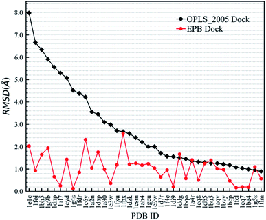 |
| | Fig. 4 Comparison of RMSD values derived from OPLS_2005 Dock and EPB Dock, as also listed in Table 2. | |
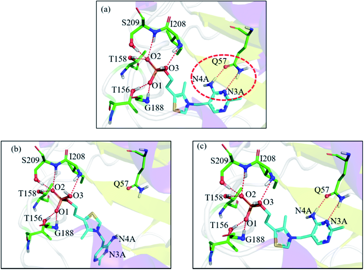
In the 1g4s case, the RMSD value was greatly improved when using EPB Dock (from 4.52 Å in OPLS_2005 Dock to 0.13 Å in EPB Dock). It is informative to analyze the detailed interaction pattern for the 1g4s case. Fig. 5 shows different interaction structures between the ligand and protein derived from three sources: the co-crystal structure, OPLS_2005 docked structure and the EPB docked structure. There are two intermolecular hydrogen bonds between the side chains of the residue Q57 and the ligand in the native co-crystal structure (Fig. 5a). The docking geometry from EPB Dock has the same hydrogen bonds as that in the native crystal structure. However, these two hydrogen bonds were lost in OPLS_2005 Dock, which causes part of the ligand to rotate to another direction and produces a large RMSD value. The atom N4A of the ligand is involved in a hydrogen bond interaction with residue Q57. The atomic charge for N4A was −0.92 in OPLS_2005 force field. In the EPB method, the charge of N4A was −1.06 due to polarization. The polarizable effect in EPB Dock stabilizes the intermolecular hydrogen bonds and the other three cases are shown in Fig. S15.†
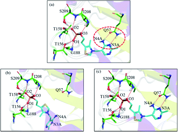 |
| | Fig. 5 Comparison of the detailed protein–ligand interaction structures in the 1g4s case: (a) native crystal structure; (b) structure derived from OPLS_2005 Dock; (c) structure derived from EPB Dock. The red dot represents the change of the hydrogen bond. | |
Optimized docking with EPB charges
In the validation study, we demonstrated that the EPB model can increase the accuracy of the docking when using ligand charge polarized by the protein from the native co-crystal structure. However, in practical virtual screening, we have no prior knowledge of the native binding mode. We thus need to perform docking first to obtain a preliminary complex structure and to derive the EPB charge based on the docked structure. Using the EPB charges thus derived, new docking is performed to obtain a presumably better structured. This process is iterated until the energy Ecvdw is essentially unchanged (typically less than 1 kcal mol−1). We call this the optimized docking and the workflow of this approach is given in Fig. 3.
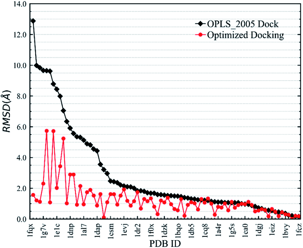
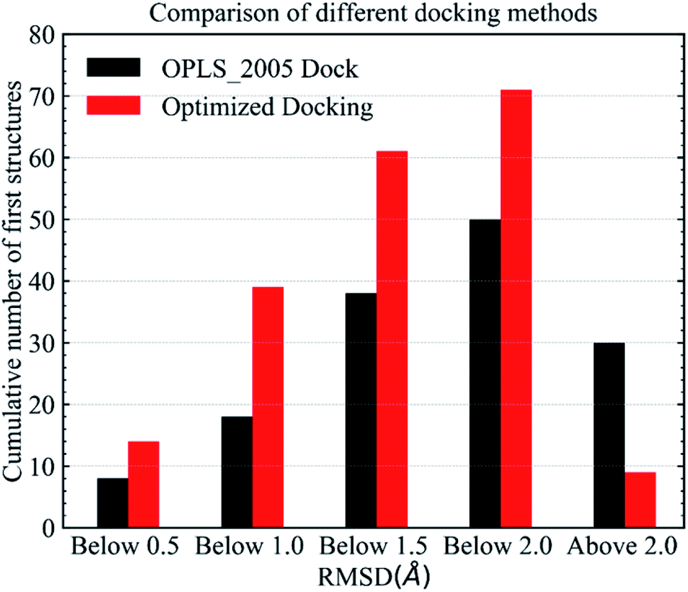
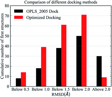
Fig. 6 shows RMSD values for different docking procedures. We can find that the RMSD values drop sharply for many cases when using the EPB iterative docking method (Optimized Docking). The maximum error was reduced from 12.88 Å to 1.57 Å in Optimized Docking (in the case of 1fqx). The average RMSD decreased from 2.83 Å to 1.85 Å. Fig. 7 plots the performance of two different docking methods through quantitatively comparing the structures under a specific RMSD cutoff. From Fig. 7, we can observe that the number of first-ranked structures with RMSD values under 1.5 Å increased from 38 in the OPLS_2005 Dock to 61 in the Optimized Docking and the number of structures with RMSD values above 2.0 Å decreased from 30 in OPLS_2005 Dock to 9 in the Optimized Docking. These results suggest that the optimized (or iterative) EPB docking method can increase the docking accuracy in many cases in practical docking tasks. There are also some cases where the improvement is limited. In some cases, the structure of water is an important factor for the correct binding pose. Since we deleted all water molecules in the test, it is difficult to make improvements in those systems with the Optimized Docking method.
 |
| | Fig. 6 RMSD changes from OPLS_2005 Dock to Optimized Docking. | |
 |
| | Fig. 7 Comparison of different methods in terms of the number of first-ranked structures obtained that are under 0.5, 1.0, 1.5, 2.0 Å and above 2.0 Å. | |
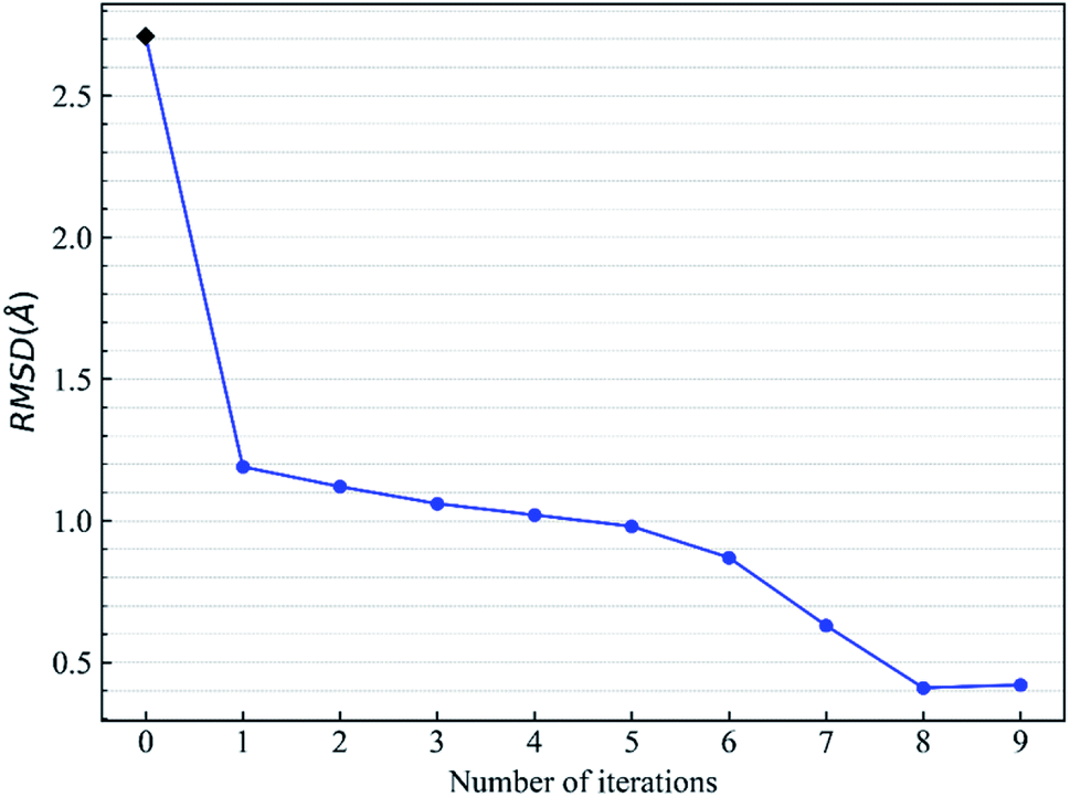
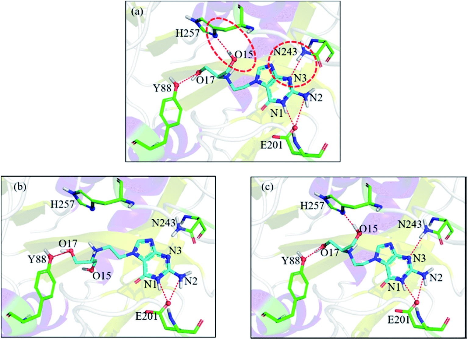
Let us focus on the 1fxu case to see how the charge values in the force field impact the final docking pose. Fig. 8 shows how the RMSD of the docked pose is improved as the number of iterative cycles is increased in optimized docking and Fig. S18† shows the detailed protein–ligand interaction in optimized docking for the 1fxu system. Fig. 8 shows that the RMSD value decreases during the iterative EPB docking process. In the 1fxu case, the RMSD of the final docked pose was, respectively, 2.71 Å and 0.41 Å for OPLS_2005 and for the optimized EPB dockings. Fig. 9 shows the detailed interaction between the ligand and protein in the crystal structure and docked structures. From the native crystal structures (Fig. 9a), we see that two hydroxyl groups of the ligand form hydrogen bonds with the side chains of the residues H257 and Y88. In the complex structure generated by OPLS_2005 Dock, the hydrogen bond between one of the hydroxyl groups and residue H257 was missing. In the docking geometry from the optimized EPB docking, both hydrogen bonds remained stable. The atoms O15 and O17 of the ligand were involved in hydrogen bond interactions with residues H257 and Y88. The atomic charges for O15 and O17 were both −0.68 in the OPLS_2005 force field. When the EPB iterative docking method was used, the charges for those two oxygen atoms were polarized to −0.79 and −0.78, respectively. Thus it can be seen that the polarized charges derived from the EPB method enhance the intermolecular hydrogen bond strength in the docking and the final docked pose tends to form more stable hydrogen bond interactions. Previous studies87–89,98,109–112 on protein dynamics in water indicate that traditional force fields underestimate the hydrogen bond strength in many cases, which could result in unstable structures in MD simulation. Fig. S16† shows the RMSD values for different docking procedures and Fig. S17† shows a comparison of the detailed protein–ligand interaction structures in another three cases.
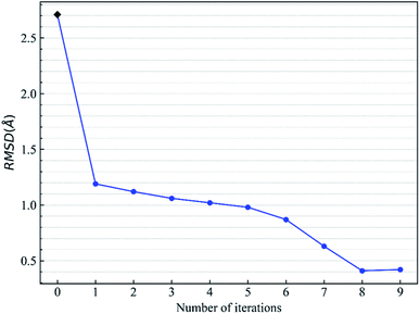 |
| | Fig. 8 Change of RMSD value with the number of iterative EBP dockings for the protein–ligand system 1fxu (pdbid). | |
 |
| | Fig. 9 Comparison of the detailed protein–ligand interaction structures in the case of 1fxu: (a) native crystal structure; (b) structure from OPLS_2005 Dock; (c) structure from optimized (iterative) EPB docking. The red dot represents the change of the hydrogen bond. | |
Conclusions
In this work, we developed the EPB model for small organic molecules and used the EPB method to optimize protein–ligand docking. In the EPB model, the charges of atoms in the polar bonds fluctuate according to their local electrostatic environments. Validation tests using polarized charges derived from native co-crystal structures suggest that the EPB method improves the docking performance by providing more accurate complex binding structures and the maximum error was reduced from 7.98 Å to 2.03 Å when using EPB Dock. Further investigation of the optimized or iterative EPB docking demonstrates that the EPB method was robust in practical docking and the average RMSD decreased from 2.83 Å to 1.85 Å in 80 co-crystal structures. In particular, the EPB optimized docking enhanced the intermolecular hydrogen bonding and thus provided a more stable complex structure. Compared with QM/MM docking procedures, the optimized or iterative EPB docking is computationally efficient since the derivation of EPB charges is efficient in the optimized docking procedure.
Python codes for the calculation of polarized ligand charge from a protein–ligand complex structure with the EPB method are freely available on GitHub (https://github.com/Xundrug/EPB).
Conflicts of interest
There are no conflicts to declare.
Acknowledgements
This work was supported by the National Key R&D Program of China (Grant No. 2016YFA0501700), the National Natural Science Foundation of China (Grant No. 21433004 and 91753103), the NYU Global Seed Grant, and the Laboratory and Equipment Management Office of ECNU. We also thank the ECNU Multifunctional Platform for Innovation (No. 001) for providing supercomputer time.
References
- X. Barril, R. E. Hubbard and S. D. Morley, Mini-Rev. Med. Chem., 2004, 4, 779–791 CAS.
- L. Ghemtio, V. I. Perez-Nueno, V. Leroux, Y. Asses, M. Souchet, L. Mavridis, B. Maigret and D. W. Ritchie, Comb. Chem. High Throughput Screening, 2012, 15, 749–769 CrossRef CAS PubMed.
- A. Lavecchia and C. Di Giovanni, Curr. Med. Chem., 2013, 20, 2839–2860 CrossRef CAS PubMed.
- A. Talevi and L. E. Bruno-Blanch, Lat. Am. J. Pharm., 2009, 28, 141–150 CAS.
- W. P. Walters, M. T. Stahl and M. A. Murcko, Drug Discovery Today, 1998, 3, 160–178 CrossRef CAS.
- B. Waszkowycz, T. D. J. Perkins, R. A. Sykes and J. Li, IBM Syst. J., 2001, 40, 360–376 Search PubMed.
- T. J. Hou and X. J. Xu, Curr. Pharm. Des., 2004, 10, 1011–1033 CrossRef CAS PubMed.
- D. B. Kitchen, H. Decornez, J. R. Furr and J. Bajorath, Nat. Rev. Drug Discovery, 2004, 3, 935–949 CrossRef CAS PubMed.
- B. K. Shoichet, Nature, 2004, 432, 862–865 CrossRef CAS PubMed.
- E. Lionta, G. Spyrou, D. K. Vassilatis and Z. Cournia, Curr. Top. Med. Chem., 2014, 14, 1923–1938 CrossRef CAS PubMed.
- A. J. Kooistra, H. F. Vischer, D. McNaught-Flores, R. Leurs, I. J. P. de Esch and C. de Graaf, Sci. Rep., 2016, 6, 28288 CrossRef CAS PubMed.
- P. Stoilov, C. H. Lin, R. Damoiseaux, J. Nikolic and D. L. Black, Proc. Natl. Acad. Sci. U. S. A., 2008, 105, 11218–11223 CrossRef CAS PubMed.
- R. Yang, W. W. Han and S. Wang, Acta Chim. Sin., 2011, 69, 1399–1402 CAS.
- D. L. Zhan, S. Wang, W. W. Han and J. S. Liu, Acta Chim. Sin., 2012, 70, 217–222 CrossRef CAS.
- U. Svajger, B. Brus, S. Turk, M. Sova, V. Hodnik, G. Anderluh and S. Gobec, Eur. J. Med. Chem., 2013, 70, 393–399 CrossRef CAS PubMed.
- M. von Korff, J. Freyss and T. Sander, J. Chem. Inf. Model., 2009, 49, 209–231 CrossRef CAS PubMed.
- X. B. Hou, J. T. Du, H. Fang and M. Y. Li, Protein Pept. Lett., 2011, 18, 440–449 CrossRef CAS PubMed.
- J. S. Wu, Y. H. Peng, J. M. Wu, C. J. Hsieh, S. H. Wu, M. S. Coumar, J. S. Song, J. C. Lee, C. H. Tsai, C. T. Chen, Y. W. Liu, Y. S. Chao and S. Y. Wu, J. Med. Chem., 2010, 53, 8770–8774 CrossRef CAS PubMed.
- X. Xue, J. L. Wei, L. L. Xu, M. Y. Xi, X. L. Xu, F. Liu, X. K. Guo, L. Wang, X. J. Zhang, M. Y. Zhang, M. C. Lu, H. P. Sun and Q. D. You, J. Chem. Inf. Model., 2013, 53, 2715–2729 CrossRef CAS PubMed.
- A. D. Andricopulo, L. B. Salum and D. J. Abraham, Curr. Top. Med. Chem., 2009, 9, 771–790 CrossRef CAS PubMed.
- C. N. Cavasotto and A. J. W. Orry, Curr. Top. Med. Chem., 2007, 7, 1006–1014 CrossRef CAS PubMed.
- M. Lower and E. Proschak, Mol. Inf., 2011, 30, 398–404 CrossRef PubMed.
- P. D. Lyne, Drug Discovery Today, 2002, 7, 1047–1055 CrossRef CAS PubMed.
- S. Moro, M. Bacilieri and F. Deflorian, Expert Opin. Drug Discovery, 2007, 2, 37–49 CrossRef CAS PubMed.
- S. Naud, I. M. Westwood, A. Faisal, P. Sheldrake, V. Bavetsias, B. Atrash, K. M. J. Cheung, M. J. Liu, A. Hayes, J. Schmitt, A. Wood, V. Choi, K. Boxall, G. Mak, M. Gurden, M. Valenti, A. D. Brandon, A. Henley, R. Baker, C. McAndrew, B. Matijssen, R. Burke, S. Hoelder, S. A. Eccles, F. I. Raynaud, S. Linardopoulos, R. L. M. van Montfort and J. Blagg, J. Med. Chem., 2013, 56, 10045–10065 CrossRef CAS PubMed.
- G. Subramanian and S. N. Rao, Bioorg. Med. Chem. Lett., 2013, 23, 6667–6672 CrossRef CAS PubMed.
- N. S. Pagadala, K. Syed and J. Tuszynski, Biophys. Rev., 2017, 9, 91–102 CrossRef CAS PubMed.
- R. A. Friesner, J. L. Banks, R. B. Murphy, T. A. Halgren, J. J. Klicic, D. T. Mainz, M. P. Repasky, E. H. Knoll, M. Shelley, J. K. Perry, D. E. Shaw, P. Francis and P. S. Shenkin, J. Med. Chem., 2004, 47, 1739–1749 CrossRef CAS PubMed.
- T. A. Halgren, R. B. Murphy, R. A. Friesner, H. S. Beard, L. L. Frye, W. T. Pollard and J. L. Banks, J. Med. Chem., 2004, 47, 1750–1759 CrossRef CAS PubMed.
- B. Kramer, M. Rarey and T. Lengauer, Proteins: Struct., Funct., Genet., 1999, 37, 228–241 CrossRef CAS.
- M. Rarey, B. Kramer, T. Lengauer and G. Klebe, J. Mol. Biol., 1996, 261, 470–489 CrossRef CAS PubMed.
- S. S. J. Cross, J. Chem. Inf. Model., 2005, 45, 993–1001 CrossRef CAS PubMed.
- G. Jones, P. Willett and R. C. Glen, J. Mol. Biol., 1995, 245, 43–53 CrossRef CAS PubMed.
- G. Jones, P. Willett, R. C. Glen, A. R. Leach and R. Taylor, J. Mol. Biol., 1997, 267, 727–748 CrossRef CAS PubMed.
- M. Verdonk, J. Cole, M. Hartshorn, C. Murray and R. Taylor, Proteins, 2003, 52, 609–623 CrossRef CAS.
- T. J. A. Ewing, S. Makino, A. G. Skillman and I. D. Kuntz, J. Comput.-Aided Mol. Des., 2001, 15, 411–428 CrossRef CAS PubMed.
- R. Abagyan, M. Totrov and D. Kuznetsov, J. Comput. Chem., 1994, 15, 488–506 CrossRef CAS.
- G. M. Morris, R. Huey, W. Lindstrom, M. F. Sanner, R. K. Belew, D. S. Goodsell and A. J. Olson, J. Comput. Chem., 2009, 30, 2785–2791 CrossRef CAS PubMed.
- O. Trott and A. J. Olson, J. Comput. Chem., 2010, 31, 455–461 CAS.
- S. Forli, R. Huey, M. E. Pique, M. F. Sanner, D. S. Goodsell and A. J. Olson, Nat. Protoc., 2016, 11, 905–919 CrossRef CAS PubMed.
- S. Cosconati, S. Forli, A. L. Perryman, R. Harris, D. S. Goodsell and A. J. Olson, Expert Opin. Drug Discovery, 2010, 5, 597–607 CrossRef CAS PubMed.
- W. F. de Azevedo and R. Dias, Curr. Drug Targets, 2008, 9, 1031–1039 CrossRef.
- L. D. Schuler, X. Daura and W. F. Van Gunsteren, J. Comput. Chem., 2001, 22, 1205–1218 CrossRef CAS.
- W. L. Jorgensen, D. S. Maxwell and J. TiradoRives, J. Am. Chem. Soc., 1996, 118, 11225–11236 CrossRef CAS.
- A. D. MacKerell, D. Bashford, M. Bellott, R. L. Dunbrack, J. D. Evanseck, M. J. Field, S. Fischer, J. Gao, H. Guo, S. Ha, D. Joseph-McCarthy, L. Kuchnir, K. Kuczera, F. T. K. Lau, C. Mattos, S. Michnick, T. Ngo, D. T. Nguyen, B. Prodhom, W. E. Reiher, B. Roux, M. Schlenkrich, J. C. Smith, R. Stote, J. Straub, M. Watanabe, J. Wiorkiewicz-Kuczera, D. Yin and M. Karplus, J. Phys. Chem. B, 1998, 102, 3586–3616 CrossRef CAS PubMed.
- G. Weber, Adv. Protein Chem., 1975, 29, 1–83 CrossRef CAS PubMed.
- C. Bissantz, B. Kuhn and M. Stahl, J. Med. Chem., 2010, 53, 5061–5084 CrossRef CAS PubMed.
- M. F. Perutz, Science, 1978, 201, 1187–1191 CrossRef CAS PubMed.
- J. B. Matthew, Annu. Rev. Biophys. Biophys. Chem., 1985, 14, 387–417 CrossRef CAS.
- P. Ren, J. Chun, D. G. Thomas, M. J. Schnieders, M. Marucho, J. Zhang and N. A. Baker, Q. Rev. Biophys., 2012, 45, 427–491 CrossRef PubMed.
- H.-X. Zhou and X. Pang, Chem. Rev., 2018, 118, 1691–1741 CrossRef CAS PubMed.
- H. Nakamura, Q. Rev. Biophys., 1996, 29, 1–90 CrossRef CAS PubMed.
- J. M. Thornton, Nature, 1982, 295, 13–14 CrossRef CAS PubMed.
- S. Lifson and A. Warshel, J. Chem. Phys., 1968, 49, 5116–5129 CrossRef CAS.
- B. R. Brooks, R. E. Bruccoleri, B. D. Olafson, D. J. States, S. Swaminathan and M. Karplus, J. Comput. Chem., 1983, 4, 187–217 CrossRef CAS.
- A. D. Mackerell, J. Comput. Chem., 2004, 25, 1584–1604 CrossRef CAS.
- H. Do and A. Troisi, Phys. Chem. Chem. Phys., 2015, 17, 25123–25132 RSC.
- D. Cole, J. Vilseck, J. Tirado-Rives, M. Payne and W. Jorgensen, J. Chem. Theory Comput., 2016, 12, 2312–2323 CrossRef CAS PubMed.
- P. S. Nerenberg and T. Head-Gordon, Curr. Opin. Struct. Biol., 2018, 49, 129–138 CrossRef CAS PubMed.
- A. Warshel and M. Levitt, J. Mol. Biol., 1976, 103, 227–249 CrossRef CAS PubMed.
- D. A. Pearlman, D. A. Case, J. W. Caldwell, W. S. Ross, T. E. Cheatham, S. Debolt, D. Ferguson, G. Seibel and P. Kollman, Comput. Phys. Commun., 1995, 91, 1–41 CrossRef CAS.
- S. Patel and C. L. Brooks, J. Comput. Chem., 2004, 25, 1–15 CrossRef CAS PubMed.
- S. Patel, A. D. Mackerell and C. L. Brooks, J. Comput. Chem., 2004, 25, 1504–1514 CrossRef CAS PubMed.
- H. A. Stern, G. A. Kaminski, J. L. Banks, R. Zhou, B. J. Berne and R. A. Friesner, J. Phys. Chem. B, 1999, 103, 4730–4737 CrossRef CAS.
- S. Patel and C. L. Brooks, Mol. Simul., 2006, 32, 231–249 CrossRef CAS.
- J. Chen and T. J. Martínez, Chem. Phys. Lett., 2007, 438, 315–320 CrossRef CAS.
- J. Chen and T. J. Martínez, in Advances in the Theory of Atomic and Molecular Systems: Conceptual and Computational Advances in Quantum Chemistry, ed. P. Piecuch, J. Maruani, G. Delgado-Barrio and S. Wilson, Springer, Netherlands, Dordrecht, 2009, vol. 19, pp. 397–415 Search PubMed.
- A. Kumar, O. Yoluk and A. D. MacKerell, J. Comput. Chem., 2020, 41, 958–970 CrossRef CAS PubMed.
- K. Vanommeslaeghe, E. Frush, C. Acharya, S. Kundu, S. Zhong, J. Shim, E. Darian, O. Guvench, P. Lopes, I. Vorobyov and A. MacKerell, J. Comput. Chem., 2009, 31, 671–690 Search PubMed.
- K. Vanommeslaeghe and A. D. MacKerell Jr, Biochim. Biophys. Acta, 2015, 1850, 861–871 CrossRef CAS PubMed.
- X. Zhu, P. Lopes and A. MacKerell, Wiley Interdiscip. Rev.: Comput. Mol. Sci., 2012, 2, 167–185 CAS.
- Y. Mao, O. Demerdash, M. Head-Gordon and T. Head-Gordon, J. Chem. Theory Comput., 2016, 12, 5422–5437 CrossRef CAS PubMed.
- C. Zhang, C. Lu, Z. Jing, C. Wu, J.-P. Piquemal, J. W. Ponder and P. Ren, J. Chem. Theory Comput., 2018, 14, 2084–2108 CrossRef CAS PubMed.
- Z. F. Jing, C. W. Liu, S. Y. Cheng, R. Qi, B. D. Walker, J. P. Piquemal and P. Y. Ren, in Annual Review of Biophysics, ed. K. A. Dill, 2019, vol. 48, pp. 371–394 Search PubMed.
- A. P. Jones, J. Crain, V. P. Sokhan, T. W. Whitfield and G. J. Martyna, Phys. Rev. B: Condens. Matter Mater. Phys., 2013, 87, 144103 CrossRef.
- J. A. Lemkul, J. Huang, B. Roux and A. D. MacKerell, Chem. Rev., 2016, 116, 4983–5013 CrossRef CAS PubMed.
- G. Lamoureux, A. D. MacKerell and B. Roux, J. Chem. Phys., 2003, 119, 5185–5197 CrossRef CAS.
- P. Cieplak, J. Caldwell and P. Kollman, J. Comput. Chem., 2001, 22, 1048–1057 CrossRef CAS.
- W. L. Jorgensen, K. P. Jensen and A. N. Alexandrova, J. Chem. Theory Comput., 2007, 3, 1987–1992 CrossRef CAS PubMed.
- J. W. Ponder, C. Wu, P. Ren, V. S. Pande, J. D. Chodera, M. J. Schnieders, I. Haque, D. L. Mobley, D. S. Lambrecht, R. A. DiStasio Jr, M. Head-Gordon, G. N. I. Clark, M. E. Johnson and T. Head-Gordon, J. Phys. Chem. B, 2010, 114, 2549–2564 CrossRef CAS PubMed.
- Z. X. Wang, W. Zhang, C. Wu, H. X. Lei, P. Cieplak and Y. Duan, J. Comput. Chem., 2006, 27, 781–790 CrossRef CAS.
- J. Wang, P. Cieplak, J. Li, T. Hou, R. Luo and Y. Duan, J. Phys. Chem. B, 2011, 115, 3091–3099 CrossRef CAS PubMed.
- R. A. Friesner, in Peptide Solvation and H-Bonds, ed. R. L. Baldwin and D. Baker, 2005, vol. 72, pp. 79–104 Search PubMed.
- P. Cieplak, F.-Y. Dupradeau, Y. Duan and J. Wang, J. Phys.: Condens. Matter, 2009, 21, 333102 CrossRef PubMed.
- P. E. M. Lopes, B. Roux and A. D. MacKerell Jr, Theor. Chem. Acc., 2009, 124, 11–28 Search PubMed.
- H. B. Yu and W. F. van Gunsteren, Comput. Phys. Commun., 2005, 172, 69–85 CrossRef CAS.
- X. D. Xiao, T. Zhu, C. G. Ji and J. Z. H. Zhang, J. Phys. Chem. B, 2013, 117, 14885–14893 CrossRef CAS PubMed.
- J. Chen, L. L. Duan, C. G. Ji and J. Z. H. Zhang, Front. Mol. Biosci., 2018, 4, 101 CrossRef.
- L. L. Duan, T. Zhu, C. G. Ji, Q. G. Zhang and J. Z. H. Zhang, Phys. Chem. Chem. Phys., 2017, 19, 15273–15284 RSC.
- C. Hensen, J. C. Hermann, K. H. Nam, S. H. Ma, J. L. Gao and H. D. Holtje, J. Med. Chem., 2004, 47, 6673–6680 CrossRef CAS PubMed.
- A. E. Cho, V. Guallar, B. J. Berne and R. Friesner, J. Comput. Chem., 2005, 26, 915–931 CrossRef CAS PubMed.
- A. E. Cho and D. Rinaldo, J. Comput. Chem., 2009, 30, 2609–2616 CrossRef CAS PubMed.
- J. Y. Chung, J.-M. Hah and A. E. Cho, J. Chem. Inf. Model., 2009, 49, 2382–2387 CrossRef CAS PubMed.
- R. B. Murphy, D. M. Philipp and R. A. Friesner, J. Comput. Chem., 2000, 21, 1442–1457 CrossRef CAS.
- D. M. Philipp and R. A. Friesner, J. Comput. Chem., 1999, 20, 1468–1494 CrossRef CAS.
- Z. Bikadi and E. Hazai, J. Cheminf., 2009, 1, 15 Search PubMed.
- P. Chaskar, V. Zoete and U. F. Roehrig, J. Chem. Inf. Model., 2014, 54, 3137–3152 CrossRef CAS PubMed.
- C. G. Ji, X. D. Xiao and J. Z. H. Zhang, J. Chem. Theory Comput., 2012, 8, 2157–2164 CrossRef CAS PubMed.
- T. Darden, D. York and L. Pedersen, J. Chem. Phys., 1993, 98, 10089–10092 CrossRef CAS.
- S. Piana, K. Lindorff-Larsen, R. M. Dirks, J. K. Salmon, R. O. Dror and D. E. Shaw, PLoS One, 2012, 7, e39918 CrossRef CAS PubMed.
- R. W. Pastor, B. R. Brooks and A. Szabo, Mol. Phys., 1988, 65, 1409–1419 CrossRef.
- J. P. Ryckaert, G. Ciccotti and H. J. C. Berendsen, J. Comput. Phys., 1977, 23, 327–341 CrossRef CAS.
- A. D. Becke, J. Chem. Phys., 2014, 140, 18A301 CrossRef PubMed.
- W. Kung, in Geometry and Phase Transitions in Colloids and Polymers, 2009, vol. 79, pp. 38–48 Search PubMed.
- J. A. Plumley and J. J. Dannenberg, J. Comput. Chem., 2011, 32, 1519–1527 CrossRef CAS PubMed.
- M. Frisch, G. Trucks, H. Schlegel, G. Scuseria, M. Robb, J. Cheeseman, G. Scalmani, V. Barone, B. Mennucci, G. Petersson, H. Nakatsuji, M. Caricato, X. Li, H. Hratchian, A. Izmaylov, J. Bloino, G. Zheng, J. Sonnenberg, M. Hada and D. Fox, Gaussian Inc., Wallingford CT, 2009.
- W. Literature, V. Babin, J. Berryman, R. M. Betz, Q. Cai, D. S. Cerutti, T. Cheatham, T. Darden, R. Duke, H. Gohlke, A. Götz, S. Gusarov, N. Homeyer, P. Janowski, J. Kaus, I. Kolossváry, A. Kovalenko, T.-S. Lee and P. A. Kollman, AMBER 14, University of California, San Francisco, 2014 Search PubMed.
- H. Berman, Biophys. J., 2000, 78, 267A CrossRef.
- C. Ji, Y. Mei and J. Z. H. Zhang, Biophys. J., 2008, 95, 1080–1088 CrossRef CAS PubMed.
- C. G. Ji and J. Z. H. Zhang, J. Phys. Chem. B, 2009, 113, 16059–16064 CrossRef CAS PubMed.
- C. G. Ji and J. Z. H. Zhang, J. Comput. Chem., 2012, 33, 1416–1420 CrossRef CAS PubMed.
- L. L. Duan, Y. Gao, C. G. Ji, Y. Mei, Q. G. Zhang, B. Tang and J. Z. H. Zhang, Sci. China: Chem., 2014, 57, 1708–1715 CrossRef CAS.
Footnote |
| † Electronic supplementary information (ESI) available. See DOI: 10.1039/d0ra01483d |
|
| This journal is © The Royal Society of Chemistry 2020 |
Click here to see how this site uses Cookies. View our privacy policy here. 
 Open Access Article
 This Open Access Article is licensed under a Creative Commons Attribution-Non Commercial 3.0 Unported Licence
 *abcd
*abcd