
 Open Access Article
 This Open Access Article is licensed under a
 Creative Commons Attribution 3.0 Unported Licence
Mesoporous Cu–Cu2O@TiO2 heterojunction photocatalysts derived from metal–organic frameworks†
Wenling Zhao and
Chengcheng Liu *
*
Institute of Molecular Sciences and Engineering, Institute of Frontier and Interdisciplinary Science, Shandong University, Qingdao 266237, P. R. China. E-mail: chengcheng.liu@sdu.edu.cn
First published on 9th April 2020
Abstract
This study reveals a unique Cu–Cu2O@TiO2 heterojunction photocatalyst obtained with metal–organic framework as the precursor, which can be utilized in dye photodegradation under visible light irradiation. The composition, structure, morphology, porosity, optical properties and photocatalytic performance of the obtained catalysts were all investigated in detail. The Cu–Cu2O@TiO2 nanocomposite is composed of lamellar Cu–Cu2O microspheres embedded by numerous TiO2 nanoparticles. Methylene blue, methyl orange and 4-nitrophenol were used as model pollutants to evaluate the photocatalytic activity of the Cu–Cu2O@TiO2 nanocomposite for dye degradation under visible light irradiation. Nearly 95% decolourisation efficiency of Methylene blue was achieved by the Cu–Cu2O@TiO2 photocatalyst within 3 h, which is much higher than that of TiO2 or Cu2O catalysts. The excellent photocatalytic activity was primarily attributed to the unique MOF-based mesoporous structure, the enlarged photo-adsorption range and the efficient separation of the charge carriers in the Cu–Cu2O@TiO2 heterojunction.
1. Introduction
Photocatalysis has emerged as an economical and environmentally benign reaction route and has shown potential in tackling resource depletion in recent years.1,2 In this process, the light energy can be converted into the energy required for chemical reactions. Semiconductors, e.g., TiO2, Cu2O, Cu2−xSe, and g-C3N4 etc., with relatively low cost, high catalytic activity and stability are commonly used as photocatalysts.3–6 Silver based nanocomposites are also photocatalysts for dye degradation.7,8 Titanium dioxide (TiO2), known as one of the most important n-type semiconductors, has been recognised as a photocatalyst owing to its own characteristics such as good photostability, low cost and environmental friendliness.3,4 Due to its wide bandgap (anatase, 3.2 eV), TiO2 can only be excited by ultraviolet light for photocatalytic reactions.9 However, ultraviolet light only accounts for 5% of the solar spectrum, while visible light accounts for 48% of the total light energy.10 At the same time, the photogenerated positive and negative charge carriers, electron–hole pairs, tend to recombine in single-phase semiconductors, resulting in the low efficiency of photocatalytic reactions. To overcome these shortcomings, a great number of efforts have been devoted to modifying the TiO2 nanostructure surface or combining single-phase TiO2 with non-metals, metals, and organic molecules to form semiconductor composites. It has been reported that the combination of two or more desirable semiconductors or metal nanoparticles is an effective method to create nanocomposites with higher photocatalytic activity.11,12 Because the photogenerated electrons are found to be transferable between them in a composite, which can significantly promote the separation of electron–hole pairs and finally improve photocatalytic efficiency. It is well known that narrow-bandgap semiconductor can serve as the primary absorber of visible light in a coupled semiconductor. Among narrow-bandgap semiconductors, Cu2O is a naturally occurring p-type semiconductor with a wide range of applications such as photocatalytic water splitting, gas sensing, and degradation of organic pollutants.13–15 Different from TiO2, Cu2O can be easily excited by visible light to generate electron and hole pairs on account of its lower bandgap energy (2.17 eV).16 The matched band structures of Cu2O and TiO2 are sufficient to promote the physical separation of charge carriers, and also significantly inhibit the recombination rate in their nanocomposite, thereby increasing the light-harvesting efficiency and enhancing photocatalytic activity.17 Moreover, the use of Cu coupled to Cu2O and TiO2 has shown better performance owing to the surface plasmon resonance (SPR) effect of Cu nanoparticles.18,19 However, according to the literature, the synthesis of Cu–Cu2O–TiO2 nanocomposites requires sophisticated equipment, and it is very difficult to obtain a well-designed unique three-dimensional morphology of the nanocomposites. For this reason, the development of a controllable and straightforward synthetic route for Cu–Cu2O–TiO2 photocatalysts with novel structures and remarkable photocatalytic performance under visible light remains a challenge.Catalysts with controlled porosity and morphology have shown great advantages in catalysis owing to their good mass transfer property, large surface area and abundant reactive sites.20 Due to its unique porous structure and tuneable organic linkers/metal clusters, MOFs have attracted considerable attention as precursors to derive various useful porous catalytic materials by thermal or chemical treatments. For example, thermal treatment of MOFs in an inert atmosphere can produce highly porous carbon with a high specific surface area (∼3000 m2 g−1).21 Besides, direct heat treatment of MOF in the optimised heating conditions in a nitrogen or air atmosphere can lead them to decompose into their corresponding metal oxides.22 In general, the derivative metal oxides have the same structure as the parent MOFs, and show much higher surface area than metal oxides produced by other methods. The high surface area, controllable porous architectures and tuneable composition of MOF-derived metal oxides along with the possibilities to combine them with different catalytic active metal oxides make them attractive candidates for the catalytic applications.23 Over the years, metal-oxide semiconductors (MOS) have received the extensive concern on account of their high photo-response activity and nontoxicity in the application of solar energy conversion and environmental pollution reduction.24
Based on the above considerations, this work utilized cheap copper MOFs, NOTT-100 (Cu), as precursor to develop a kind of photocatalytic-active porous Cu–Cu2O@TiO2 triple junction nanocomposite, which was built by Cu–Cu2O microspheres coated by a great many TiO2 nanoparticles. To investigate the structure and morphology of Cu–Cu2O@TiO2 nanocomposite and its optical properties, XRD, SEM, UV-vis, etc. were conducted. The Cu–Cu2O@TiO2 shows good photocatalytic activity in organic pollutants degradation under visible-light illumination. The synergic effect endows the composite higher performance and the enhancement of the catalysis was attributed to the special heterojunction structure and the mesoporous structure.
2. Results and discussion
2.1 Structure and morphology
In this project, Cu–Cu2O@TiO2 nanocomposite was synthesised by an easy two-step method. NOTT-100(Cu) lamellar microstructures were obtained firstly using the solvothermal method, and then tetra-n-butyl orthotitanate, the Ti(IV) precursors, were adsorbed on the porous surface of MOF microstructures, taking advantage of porosity of MOFs and strong hydrolysis ability of Ti(IV) precursors to produce the Cu–Cu2O@TiO2 nanocomposite after calcination (Scheme 1). Firstly, tetra-n-butyl orthotitanate was dissolved in the NOTT-100(Cu) suspension in n-hexane. Abundant Ti4+ cations would be diffused and adsorbed onto the surfaces of the porous NOTT-100(Cu) and partially hydrolysed with water molecules on the MOFs. After the separation of solvent n-hexane, Ti4+ cations further hydrolysed quickly with the moisture in the air. With the calcination, NOTT-100(Cu) totally decomposed to Cu2O at 550 °C in 2 h. Then part of the Cu2O decomposed to Cu when heated continuously to 4 h (Fig. S2†). Hence Cu2O and Cu coexist under the adopted calcination temperature and time conditions. Besides, a large number of TiO2 nanoparticles were formed from hydrolysed products, obtaining TiO2 nanoparticles grown on Cu–Cu2O microspheres.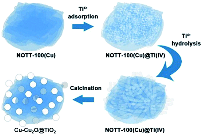 | ||
| Scheme 1 Synthesis procedure of Cu–Cu2O@TiO2 nanocomposite. | ||
This adsorption and hydrolysis procedure did not influence the unique structure of NOTT-100(Cu) as shown in Fig. S1.† The calcination temperature of 550 °C and duration of 4 hours are selected as the optimised calcination condition for Cu–Cu2O formation without CuO (Fig. S2†). For this sample, all diffraction peaks in the XRD pattern are almost consistent with each value of the standard patterns of anatase phase TiO2 (JCPDS card no. 21-1272), Cu (JCPDS card no. 04-0836) and Cu2O (JCPDS card no. 05-0667), indicating the good-crystalline character of the samples.
In Fig. 1, SEM and TEM images illustrate the morphologies and microstructures of NOTT-100(Cu) and Cu–Cu2O@TiO2, respectively. It can be clearly seen that the Cu–Cu2O@TiO2 nanocomposite consists of flower-like lamellar microspheres with a diameter of about 2.5 μm keeping the primary structure of NOTT-100(Cu), and a large number of nanoparticles covered on the surface of lamellar microstructures. In addition, Fig. 1e shows the HRTEM image of the Cu–Cu2O@TiO2, from which it can be seen that the lattice space of 0.366 nm corresponds to (116) planes of TiO2. The lattice space of 0.241 nm corresponds to (111) planes of Cu, and the lattice space of 0.236 nm corresponds to (200) planes of Cu2O. EDS mapping shows the element distribution of O, Ti and Cu in Cu–Cu2O@TiO2 (Fig. 1f and S3†). These characterizations demonstrate that almost all TiO2 nanoparticles attached to the Cu–Cu2O surface are separately and evenly distributed. Hence, it can be concluded that the as-prepared rough Cu–Cu2O@TiO2 nanocomposite is composed of the MOF-like lamellar Cu–Cu2O microspheres embedded by a great many TiO2 nanoparticles.
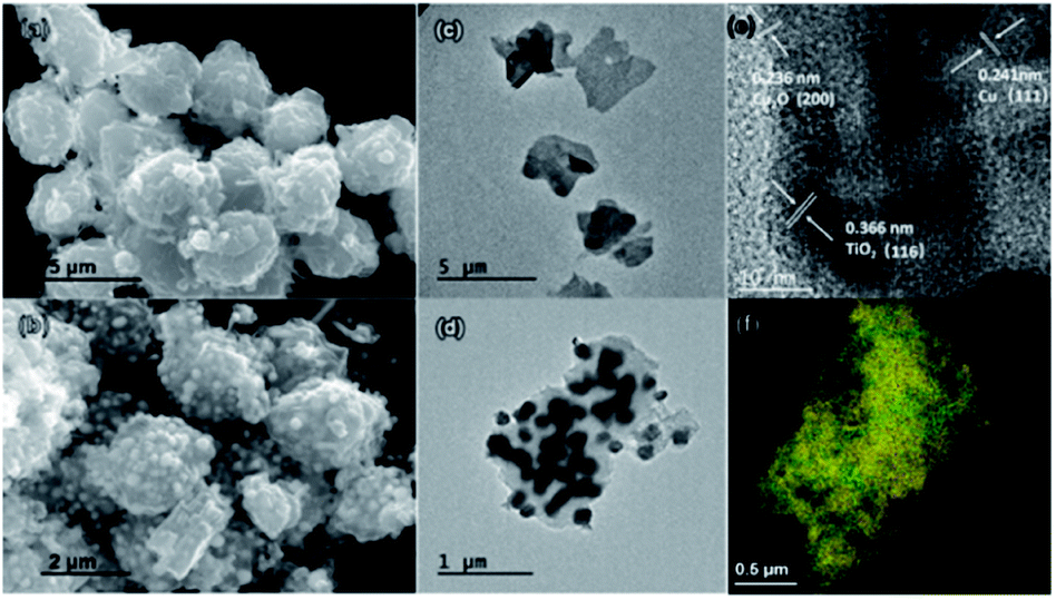 | ||
| Fig. 1 SEM and TEM images of the NOTT-100(Cu) (a) and (c); Cu–Cu2O@TiO2 (b) and (d). HRTEM images of the Cu–Cu2O@TiO2 (e). EDS mapping of O (red), Ti (green) and Cu (yellow) in Cu–Cu2O@TiO2 (f). | ||
The porosity of the Cu–Cu2O@TiO2 sample was investigated by N2 adsorption–desorption isotherm patterns (Fig. S4†). The isotherm is similar to type-IV IUPAC isotherm which indicates the Cu–Cu2O@TiO2 sample is a kind of mesoporous material. The average pore diameter is determined about 7 nm. It is reported that mesoporous structure has a large specific surface area, providing a large number of active centers for the reaction. Moreover, the existence of mesoporous structure is conducive to multiple light scattering or reflection, thus enhancing the capture of exciting light and improving the photocatalytic activity.25–27 The BET surface area and the pore volume of Cu–Cu2O@TiO2 are 187 m2 g−1 and 0.298 cm3 g−1 respectively. The BET surface is much higher than the reported Cu–Cu2O–TiO2 composite (50m2 g−1) owing to the porous properties.28 The mesopores are assumed to result from the loss of organic ligands in MOF during calcination. Therefore, the Cu–Cu2O@TiO2 nanocomposite is revealed to have an excellent porous property, which can be another advantage for the catalytic application.
2.2 XPS analysis
XPS studies were conducted over the Cu–Cu2O@TiO2 in order to understand the chemical state and chemical environment of the Cu and Ti elements of the composite. Fig. 2a shows the XPS survey spectrum for Cu–Cu2O@TiO2 composites, which demonstrates the existence of Cu, Ti, O and C elements in the sample. The spectra were calibrated with C 1s as standard. Fig. 2b shows the high resolution XPS spectrum in the region of Cu 2p for Cu–Cu2O@TiO2. The main peak centered at 932.4 and 952.4 eV of Cu (2p3/2) and Cu (2p1/2) are readily assigned to either Cu(0) or Cu(I). The two binding energy peaks located at 934.1 and 954.0 eV with two extra shake-up satellites were assigned to Cu (2p3/2) and Cu (2p1/2) of Cu(II).29 This was commonly attributed to the oxidation of Cu(I) during sample preparation for analysis as there is no CuO shown in the XRD spectrum.30 The high resolution XPS spectrum of Ti 2p in Cu–Cu2O@TiO2 (Fig. 2c) centered in 458.3 and 464.0 eV can be assigned to Ti (2p3/2) and Ti (2p1/2) for Ti(IV).31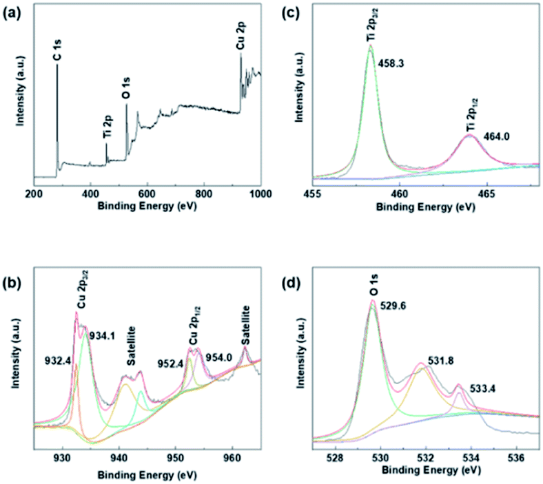 | ||
| Fig. 2 XPS spectra of Cu–Cu2O@TiO2: (a) XPS survey spectrum, (b) Cu 2p spectrum, (c) Ti 2p spectrum and (d) O 1s spectrum. | ||
2.3 Optical properties and photocatalytic performance
The UV-vis diffuse reflectance spectroscopy was employed to investigate the optical properties of the Cu–Cu2O@TiO2 sample. The UV-vis absorption spectra of pure Cu–Cu2O@TiO2 nanocomposite, pure commercially available TiO2 (anatase) nanoparticles, pure NOTT-100(Cu) are shown in Fig. 3a. It can be clearly seen that the pure TiO2 presents strong absorption of ultraviolet light at wavelengths below 400 nm. As desired, the Cu–Cu2O@TiO2 nanocomposite exhibits much stronger absorption, especially in wavelengths ranging from 400 to 600 nm, which could be attributed to the interplay of Cu2O and TiO2 and the narrow band-gap of Cu2O.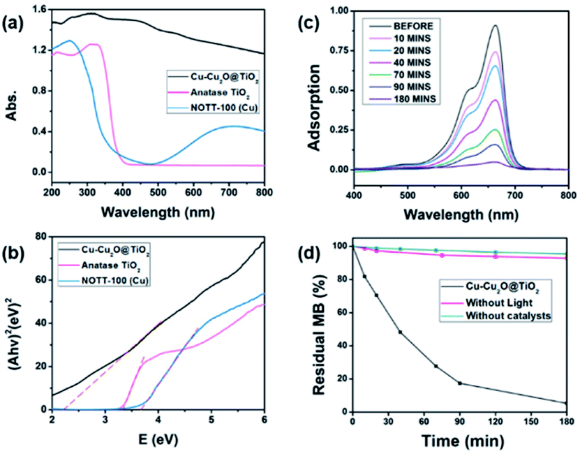 | ||
| Fig. 3 (a) UV-vis diffuse-reflectance spectra and (b) Tauc plots of (Ahν)2 versus (hν) of Cu–Cu2O@TiO2, TiO2(anatase) and NOTT-100(Cu), respectively; (c) UV-vis absorption spectra for MB solution in the presence of Cu–Cu2O@TiO2 nanocomposite under the visible light irradiation at different time intervals; (d) MB residual under different conditions. | ||
Using the Tauc plot of (Ahν)2 versus photon energy (hν), the optical bandgap of the direct allowed semiconductor could be roughly determined.32 As shown in Fig. 3b, the measured bandgap of pure TiO2 and pure NOTT-100(Cu) is about 3.34 eV and 3.67 eV, respectively. As the coupling of Cu–Cu2O has a significant effect on the band-gap energy of TiO2, the estimated band-gap of the Cu–Cu2O@TiO2 nanocomposite is 2.25 eV, which is much lower than band-gap of either pure TiO2 or pure NOTT-100(Cu) but little higher than that of reported pure Cu2O (2.17 eV).33 These results indicate that the interfaces of Cu–Cu2O and TiO2 are combined intimately, and the band edges achieve good matching between the two semiconductors. Hence, the visible light harvest and high-efficient separation of electron and hole pairs are more likely to accomplish in the Cu–Cu2O@TiO2 nanocomposite.
In this work, methylene blue (MB), methyl orange (MO) and 4-nitrophenol (4-NP) were utilised as model pollutants to investigate the photocatalytic activity of Cu–Cu2O@TiO2 nanocomposite under the visible light irradiation. Fig. 3c exhibits the UV-vis absorption spectrum of the MB aqueous solution with 5 mg of Cu–Cu2O@TiO2 as photocatalyst exposed to the visible light for different durations. And it is observed that the characteristic absorption peak of MB at 664 nm becomes weaker rapidly when the exposure time is extended. After about 180 minutes, the peak almost disappears. Meanwhile, the MB aqueous solution turned colourless gradually from beginning blue under the irradiation. This degradation efficiency of MB is much higher than that of the reported Cu2O@TiO2 composite or Cu–TiO2/RGO catalysts.34,35
Blank tests (without any catalysts or without light) were completed which exhibit a slight fall of the MB concentration (Fig. 3d). The results of the MB photodegradation with different photocatalysts under the same conditions are compared in Fig. S5.† After 180 minutes of the visible-light irradiation, about 12%, 11% and 30% of MB are decomposed catalysed by the pure commercial anatase nanoparticles, NOTT-100(Cu) and Cu2O obtained from the calcination of NOTT-100(Cu), respectively. These results also suggest that the Cu–Cu2O@TiO2 nanocomposite has a much more excellent photocatalytic activity, compared to either pure TiO2, Cu2O or NOTT-100(Cu) under the visible light irradiation (Table S1†). To further explore the practical applications of the Cu–Cu2O@TiO2 photocatalyst, the repeatability test was completed by recycling the sample three times in the degradation of MB under the same condition. In Fig. S6,† MB is found to be almost degraded entirely in each cycle, which suggests that there is no apparent decrease in photocatalytic activity in the three cycles. This result indicates that the Cu–Cu2O@TiO2 nanocomposite possesses good cycling stability for the photodegradation of MB.
When it was applied to the photodegradation of MO and 4-NP, Cu–Cu2O@TiO2 also shows good activity compared with pure TiO2 and NOTT-100(Cu). It is found that the characteristic absorptions of MO at 464 nm (Fig. S7†) decrease under the visible light irradiation. As shown in Fig. S8,† after irradiation for 3 h, residual MO and 4-NP drop to 38% and 62%, respectively.
There are many reasons for this excellent photocatalytic performance of the Cu–Cu2O@TiO2 nanocomposite, and the most crucial one can be ascribed to the efficient separation of the charge carriers at the closely combined Cu–Cu2O@TiO2 heterojunctions. Pure TiO2 nanoparticles can only be activated by ultraviolet light, whereas for Cu–Cu2O@TiO2 nanocomposite the photo-response range is widely extended. Therefore much more energy from the visible light can be utilised under the natural light irradiation. Moreover, the efficient separations of the photogenerated electron–hole pairs are driven by the heterojunction of p-type Cu2O and n-type TiO2 semiconductor. Although the TiO2 nanoparticles cannot be excited by the visible light, Cu2O can act as the primary absorber of visible light and be activated to generate electron–hole pairs. As shown in Scheme 2, the position of the conduction band (CB) in Cu2O is higher than that of TiO2, and so the active electrons (e−) in the CB of Cu2O tend to transfer to the CB of TiO2 when irradiated by the visible light. The photo-generated holes can effectively migrated to and accumulated at Cu2O, and meanwhile this will promote the acceleration of the photogenerated electron–hole separation in Cu2O and also curb the recombination of electron–hole pairs. In addition, the SPR electrons of Cu have enough energy to overcome the Schottky barrier formed on the Cu/Cu2O interfaces, thus the SPR effect of Cu excited by the visible light also enable the electrons transfer to the Cu2O.36,37 In the catalytic process, the excited electrons would migrate to the catalyst surface where they could be trapped by the absorbed oxygen, thereby generating ˙O2− radicals. Then the oxidative H2O2 and ˙OH radicals can be produced by the reaction of those ˙O2− radicals and H+. Finally, the organic pollutant molecules are oxidised and degraded by these strong oxidative radicals.38 Moreover, the porosity of the Cu–Cu2O@TiO2 nanocomposite should not be ignored as the high surface area can lead to better catalytic performance. Therefore, the Cu–Cu2O@TiO2 nanocomposite exhibits a remarkable photocatalytic performance under the visible light irradiation.
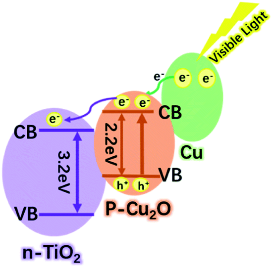 | ||
| Scheme 2 Photocatalytic mechanism of Cu–Cu2O@TiO2 nanocomposite under visible light irradiation. | ||
3. Experimental section
3.1 Materials and methods
XRD patterns were recorded on a Philip X'Pert with Cu-Kα radiation (λ = 0.154184 nm) at 40 kV and 50 mA with a scanning rate of 5° min−1. Scanning electron microscopy (SEM) was performed on FEI XL30 ESEM-FEG. Ultraviolet-visible (UV-vis) diffuse-reflectance spectra were analysed at room temperature by UV-2600 (Shimadzu, Japan) with BaSO4 and DI water as the references, which were converted to absorption spectra using the Kubelka–Munk method. Nuclear magnetic resonance (NMR) was recorded on Bruker Ascend TM 400; infrared spectroscopy (IR) was carried on ATR.3.2 Synthetic procedures
![[thin space (1/6-em)]](https://www.rsc.org/images/entities/char_2009.gif) :3:2 v/v/v) in a 250 mL round-bottom flask. Then CTAB (9.6 g, 26.34 mmol) was added to the mixture and mixed thoroughly. The suspension was heated with continuous stirring in a 65 °C oil bath for 24 hours, and a large amount of microcrystalline product precipitated. The blue crystalline product was washed with warm DMF (65 °C), H2O and acetone in turn, and dried briefly in the air. Yield: 745 mg (82.8%).
:3:2 v/v/v) in a 250 mL round-bottom flask. Then CTAB (9.6 g, 26.34 mmol) was added to the mixture and mixed thoroughly. The suspension was heated with continuous stirring in a 65 °C oil bath for 24 hours, and a large amount of microcrystalline product precipitated. The blue crystalline product was washed with warm DMF (65 °C), H2O and acetone in turn, and dried briefly in the air. Yield: 745 mg (82.8%).3.3 Photocatalytic experiments
The model organic pollutant, MB, was utilised to investigate the photocatalytic performance of samples under visible-light illumination. First, a quantity of 5 mg of the synthesised Cu–Cu2O@TiO2 was dispersed in 12.5 mL of deionised water (DI) (0.4 mg mL−1) via ultrasonication for 1 minute in a 60 mL glass beaker, and then 12.5 mL of a 4 × 10⁻⁵ M MB aqueous solution was added. A 300 W xenon lamp (CEL- HXF300, Beijing Aulight Co., Ltd., Beijing, PRC) served as the light source, equipped with a 400 nm cut-off glass sheet to filter out all the light at wavelengths below 400 nm. At the same time, the photocatalytic reactor and the visible light source was shielded by black cardboards during the reaction to remove the interference from outside light. Before illuminated by the visible light, the mixed solution of the photocatalyst and MB was under continuous magnetic stirring in darkness for 1 hour to establish an adsorption–desorption equilibrium. The suspension was also stirred during the whole irradiation process. At each time interval, 2 mL of the reaction liquid was taken out by a clean syringe, and the photocatalyst was removed by centrifugation at 10000 rpm for 2 minutes. Then the clear MB solution was analysed by the Model UV-2600 spectrophotometer, with the measured maximum absorption at λmax = 664 nm. NOTT-100(Cu), NOTT-100(Cu)@Ti(IV), TiO2 anatase nanoparticles, Cu2O after calcination of NOTT-100(Cu) were also applied into the degradation experiments of MB under the same experimental conditions for comparison purpose. For the degradation of MO and 4-NP, the experimental conditions are similar with MB, but with different initial concentrations. For MO, the concentrations of MO and the photocatalyst are 30 mg L−1 and 0.25 mg mL−1, respectively. For 4-NP, the fixed initial concentrations of 4-NP and the photocatalyst in the solution were 10 mg L−1 and 0.36 mg mL−1, respectively. All the photocatalytic degradation experiments were repeated three times.
4. Conclusions
In summary, the Cu–Cu2O@TiO2 mesoporous nanocomposite was successfully obtained by a facile two-step route, and its application in the photocatalytic degradation of organic pollutants under the visible light irradiation was utterly investigated. The Cu–Cu2O@TiO2 nanocomposite presents a lamellar Cu–Cu2O microsphere, embedded by numerous TiO2 nanoparticles. In the photodegradation of MB with the Cu–Cu2O@TiO2 nanocomposite, nearly 100% decolorization efficiency was achieved under the visible light in 3 h. The excellent photocatalytic property of the Cu–Cu2O@TiO2 nanocomposite can be ascribed to the unique mesoporous structure constructed from MOFs, the enlarged photo-adsorption range and also the efficient separation of the electron–hole pairs in its heterojunction. These characteristics indicate the Cu–Cu2O@TiO2 nanocomposite has huge potential for photodegradation of organic pollutants from water and the other environmental discharge.Conflicts of interest
There are no conflicts to declare.Acknowledgements
This work was supported by the Fundamental Research Funds of Shandong University (no. 2019GN109).References
- M. D. Karkas, B. S. Matsuura and C. R. J. Stephenson, Science, 2015, 349, 1285 CrossRef CAS PubMed
.
- H. H. Huo, X. D. Shen, C. Y. Wang, L. L. Zhang, P. Rose, L. A. Chen, K. Harms, M. Marsch, G. Hilt and E. Meggers, Nature, 2014, 515, 100 CrossRef CAS PubMed
- A. Fujishima and K. Honda, Nature, 1972, 238, 37 CrossRef CAS
- M. R. Hoffmann, S. T. Martin, W. Choi and D. W. Bahnemann, Chem. Rev., 1995, 95, 69 CrossRef
- W. W. Zhong, S. J. Shen, S. S. Feng, Z. P. Lin, Z. P. Wang and B. Z. Fang, CrystEngComm, 2018, 20, 7851 RSC
- G. Liao, Y. Gong, L. Zhang, H. Gao, G. J. Yang and B. Fang, Energy Environ. Sci., 2019, 12, 2080 RSC
- G. F. Liao, J. S. Fang, Q. Li, S. H. Li, Z. S. Xu and B. Z. Fang, Nanoscale, 2019, 11, 7062 RSC
- G. F. Liao, Y. Gong, L. Zhong, J. S. Fang, L. Zhang, Z. S. Xu, H. Y. Gao and B. Z. Fang, Nano Res., 2019, 12, 2407 CrossRef CAS
- H. X. Li, Z. F. Bian, J. Zhu, D. Q. Zhang, G. S. Li, Y. N. Huo, H. Li and Y. F. Lu, J. Am. Chem. Soc., 2007, 129, 4538 CrossRef CAS PubMed
- H. Xu, S. X. Ouyang, L. Q. Liu, P. Reunchan, N. Umezawa and J. H. Ye, J. Mater. Chem. A, 2014, 2, 12642 RSC
- Y. Y. Li, L. Y. Dang, L. F. Han, P. P. Li, J. S. Wang and Z. J. Li, J. Mol. Catal. A: Chem., 2013, 379, 146 CrossRef CAS
- D. H. Xiong, H. M. Chang, Q. Q. Zhang, S. Q. Tian, B. S. Liu and X. J. Zhao, Appl. Surf. Sci., 2015, 347, 747 CrossRef CAS
- L. I. Hung, C. K. Tsung, W. Y. Huang and P. D. Yang, Adv. Mater., 2010, 22, 1910 CrossRef CAS PubMed
- W. C. Huang, L. M. Lyu, Y. C. Yang and M. H. Huang, J. Am. Chem. Soc., 2012, 134, 1261 CrossRef CAS PubMed
- C. H. Kuo and M. H. Huang, J. Am. Chem. Soc., 2008, 130, 12815 CrossRef CAS PubMed
- Q. Yang, M. Long, L. Tan, Y. Zhang, J. Ouyang, P. Liu and A. D. Tang, ACS Appl. Mater. Interfaces, 2015, 7, 12719 CrossRef CAS PubMed
- Y. F. Wang, J. J. Tao, X. Z. Wang, M. Zhang, G. He and Z. Q. Sun, Ceram. Int., 2017, 43, 4866 CrossRef CAS
- J. Xing, Z. P. Chen, F. Y. Xiao, X. Y. Ma, C. Z. Wen, Z. Li and H. G. Yang, Chem.–Asian J., 2013, 8, 1265 CrossRef CAS PubMed
- L. Rekeb, L. Hamadou, A. Kadri, N. Benbrahim and E. Chainet, Int. J. Hydrogen Energy, 2019, 44, 10541 CrossRef CAS
- C. C. Liu, J. L. Zhang, L. Peng, X. C. Kang, B. X. Han, X. X. Sang, X. Ma and G. Y. Yang, Microporous Mesoporous Mater., 2015, 217, 6 CrossRef CAS
- P. Pachfule, X. C. Yang, Q. L. Zhu, N. Tsumori, T. Uchida and Q. Xu, J. Mater. Chem. A, 2017, 5, 4835 RSC
- C. Young, J. Kim, Y. V. Kaneti and Y. Yamauchi, ACS Appl. Energy Mater., 2018, 1, 2007 CrossRef CAS
- Y. V. Kaneti, J. Tang, R. R. Salunkhe, X. Jiang, A. Yu, K. C.-W. Wu and Y. Yamauchi, Adv. Mater., 2017, 29, 1604898 CrossRef PubMed
- X. Q. Liu, J. Iocozzia, Y. Wang, X. Cui, Y. H. Chen, S. Q. Zhao, Z. Li and Z. Q. Lin, Energy Environ. Sci., 2017, 10, 402 RSC
- B. Z. Fang, M. Kim, S. Q. Fan, J. H. Kim, D. P. Wilkinson, J. Ko and J. S. Yu, J. Mater. Chem., 2011, 21, 8742 RSC
- B. Z. Fang, Y. L. Xing, A. Bonakdarpour, S. C. Zhang and D. P. Wilkinson, ACS Sustainable Chem. Eng., 2015, 3, 2381 CrossRef CAS
- B. Z. Fang, A. Bonakdarpour, K. Reilly, Y. L. Xing, F. Taghipour and D. P. Wilkinson, ACS Appl. Mater. Interfaces, 2014, 6, 15488–15498 CrossRef CAS PubMed
- X. Q. An, H. J. Liu, J. H. Qu, S. J. A. Moniz and J. W. Tang, New J. Chem., 2015, 39, 314 RSC
- Q. Huang, F. Kang, H. Liu, Q. Li and X. D. Xiao, J. Mater. Chem. A, 2013, 1, 2418 RSC
- M. E. Aguirre, R. X. Zhou, A. J. Eugene, M. I. Guzman and M. A. Grela, Appl. Catal., B, 2017, 217, 485 CrossRef CAS
- M. Logar, I. Bracko, A. Potocnik and B. Jancar, Langmuir, 2014, 30, 4852 CrossRef CAS PubMed
- J. Tauc, Mater. Res. Bull., 1968, 3, 37 CrossRef CAS
- Z. Q. Jiang, G. Yao, X. Y. An, Y. J. Fu, L. H. Cao, W. D. Wu and X. M. Wang, Chin. Phys. B, 2014, 23, 1674 Search PubMed
- L. M. Liu, W. Y. Yang, W. Z. Sun, Q. Li and J. K. Shang, ACS Appl. Mater. Interfaces, 2015, 7, 1465 CrossRef CAS PubMed
- T. T. Pham, N. H. Chinh, H. J. Lee, T. D. Nguyen-Phan, T. H. Son, C. K. Kim and E. W. Shin, Ceram. Int., 2015, 41, 11184 CrossRef CAS
- Y. V. Kaneti, J. Tang, R. R. Salunkhe, X. C. Jiang, A. B. Yu, K. C. W. Wu and Y. Yamauchi, Adv. Mater., 2017, 29, 1604898 CrossRef PubMed
- L. Rekeb, L. Hamadou, A. Kadri, N. Benbrahim and E. Chainet, Int. J. Hydrogen Energy, 2019, 44, 10541 CrossRef CAS
- F. A. Qaraah, S. A. Mahyoub, M. E. Hafez and G. L. Xiu, RSC Adv., 2019, 9, 39561 RSC
Footnote |
| † Electronic supplementary information (ESI) available. See DOI: 10.1039/d0ra01327g |
| This journal is © The Royal Society of Chemistry 2020 |