
 Open Access Article
 This Open Access Article is licensed under a Creative Commons Attribution-Non Commercial 3.0 Unported Licence
Hypercrosslinked phenothiazine-based polymers as high redox potential organic cathode materials for lithium-ion batteries†
Ying Zhanga,
Panpan Gaoa,
Xinya Guoa,
Han Chena,
Ruiqiang Zhanga,
Ya Du *b,
Baofeng Wang*a and
Haishen Yang*a
*b,
Baofeng Wang*a and
Haishen Yang*a
aShanghai Key Laboratory of Materials Protection and Advanced Materials in Electric Power, College of Environmental and Chemical Engineering, Shanghai University of Electric Power, Shanghai 200090, China. E-mail: yanghsh@shiep.edu.cn; wangbaofeng@shiep.edu.cn
bInstitute of Advanced Synthesis, School of Chemistry and Molecular Engineering, Nanjing Tech University, Nanjing 211816, China. E-mail: ias_ydu@njtech.edu.cn
First published on 29th April 2020
Abstract
Organic cathode materials have been demonstrated to be highly promising sustainable cathode materials for rechargeable lithium-ion batteries. However, the low redox potentials, low electrical conductivity, and the undesirable dissolution in organic electrolytes greatly limit their applications. Herein, two insoluble hypercrosslinked porous conductive polymers with phenothiazine motifs, HPEPT and HPPT, were successfully accomplished with high and stable discharge potentials at 3.65 and 3.48 V versus Li/Li+. HPEPT and HPPT with good electrical conductivity exhibited outstanding rate capabilities (up to 800 mA g−1) even at a high mass loading up to 70 wt%. This study shows that excellent organic cathode materials could be achieved readily through this prudent design.
Introduction
Lithium ion batteries (LIBs) with transition-metal-based inorganic cathodes are one of the most popular rechargeable electrochemical energy storage devices (EESDs) and have been extensively used in electric vehicles and smart devices.1–3 With the increasing demand for EESDs and environmental protection, however, alternatives are highly desirable to substitute the traditional inorganic cathode materials because of their toxicity, resource scarcity, non-sustainability, and limited theoretical capacities.4–6 Redox-active organic materials, featured with resource abundance, structural diversity, environmental friendliness, tunable properties, and high capacity, etc., are regarded as one of the promising alternative cathode materials for the next-generation EESDs.7–11 Many efforts have been spent on this research area and made a lot of achievements. Various redox-active functional groups are discovered to date, such as quinones, nitroxyl, phenoxyl, carbazol, hydrazyl, etc.4,10 However, practical applications of organic cathode materials are plagued by many problems, such as the dissolution in organic electrolyte, low electrical conductivity, low redox potential, poor redox cycle stability, etc.12–14 Fortunately, the rich library of redox active motifs and chemical diversification approaches enable the creation of novel materials with enhanced properties.Amongst the family of organic redox molecules, phenothiazine is an excellent candidate for organic cathode material due to its brilliant properties. N-substituted phenothiazine could reversibly deliver two electrons with average potentials over 4 V vs. Li/Li+, and has a theoretical energy density about 1000 W h kg−1, which outperforms commercial inorganic cathodes.15–18 Furthermore, unlike most of the organic redox-active materials, phenothiazine-based materials demonstrate excellent electrical conductivity, enabling the cathode materials with high redox kinetics.19–21 Moreover, the cathode materials of phenothiazine-based are p-type electrodes with anions as charge carriers, thus are applicable for various types of metal-ion batteries (e.g. Li+, Na+, K+).15,20 But the p-type cathode materials suffers volume expansion-shrinkage effect during charging-discharging process, caused by the compensation of charges with large anions. This effect might be a serious detriment to the performance of phenothiazine-based rechargeable storage devices.22 Integration of phenothiazine moieties into a porous polymer with a rigid structure and available pores might be effectively inhibit the adverse effects because of the buffering effect of the pores. Simultaneously, hypercrosslinking of phenothiazine into a rigid porous polymer could dramatically decrease the solubility of the material and thus improve its cycling performances.17,22 However, the electrical conductivity of porous polymers is known to be extremely low, and usually extra modifications are necessary to warrant their performance as electrode materials.23,24 But how about a phenothiazine-base porous polymer? Which is a myth to be solved. To the best of our knowledge, to date, there are no reports on phenothiazine-based hypercrosslinked polymers with rigid structure yet.
With this question in mind, in this work, we synthesized two phenothiazine-functionalized polymeric networks, hypercrosslinked poly(1,3,5-tris((10-methyl-10H-phenothiazin-3-yl)ethynyl)benzene) (HPEPT) and poly(1,3,5-tris(10-methyl-10H-phenothiazin-3-yl)benzene) (HPPT) (Scheme 1) and studied their electrochemical properties as cathode materials of LIBs. HPPT demonstrated a higher specific surface of 452 m2 g−1 than that of 10 m2 g−1 for HPEPT (Fig. S5a and b†). The different linkages in the architecture would affect the topology of the neighboring benzene rings (e.g. dihydral angles, active-site distances), and prompt the different conjugation effects and thus instigate the different electric properties, which closely relate to the rate and cycling stability of HPEPT and HPPT.25 In comparison with other types of redox-active polymers with analogous structures, HPEPT and HPPT exhibit much improved electrical conductivity and higher potentials as cathode-active materials in LIBs.26 The composite electrodes of HPEPT and HPPT contain a high mass-loading of 70 wt% and present the first stable discharge potentials at 3.65 V and 3.48 V, respectively, and high reversible capacities. For the single electron redox process, the theoretical capacities of HPEPT and HPPT are 87 and 103 mA h g−1, respectively, and the theoretical energy densities of HPEPT and HPPT are 330 and 367 W h kg−1, respectively, which are among the highest in the organics. The theoretical energy densities are more than double for two electron redox processes.17
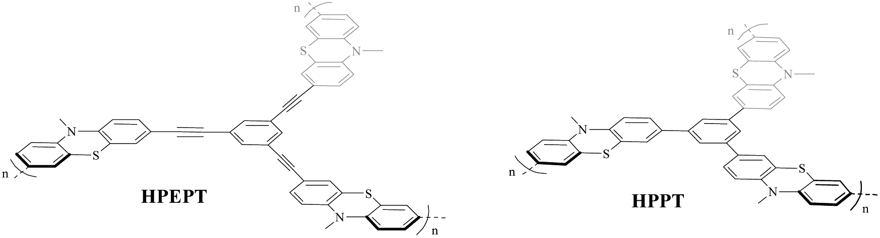 | ||
| Scheme 1 Structures of HPEPT and HPPT. | ||
Experimental
Material synthesis
As shown in Scheme 2, HPEPT and HPPT are synthesized from the same intermediate 1, which was prepared in four steps from commercially available phenothiazine. The synthetic details of 1 can be found in ESI.†27–31 HPEPT and HPPT were synthesized by using Sonogashira coupling reaction and acetylene trimerization reaction, respectively, as follow.32,33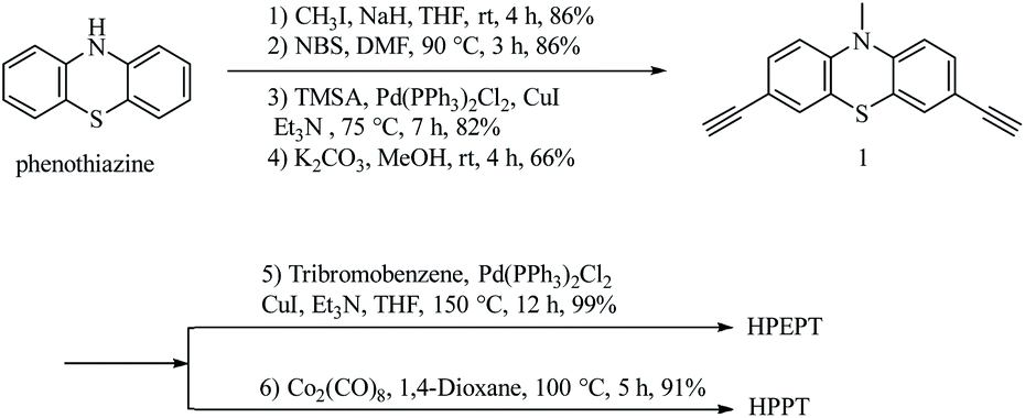 | ||
| Scheme 2 Synthesis of HPEPT and HPPT. | ||
Electrochemical measurements
The electrochemical tests of HPEPT and HPPT as cathode active materials were assembled in an argon-filled glove box using 2016 coin-type cells. The composite electrodes containing 70 wt% as-prepared polymers, 20 wt% acetylene black, 10 wt% PVDF binder in N-methyl-2-pyrrolidone (NMP). The obtained mixture was coated on aluminum foil and dried at 80 °C for 12 h. The dried electrode was cut into a round shape of 14 mm in diameter and the as-prepared polymers mass loading is about 1 mg cm−2. The cells were assembled with lithium metal as the anode electrode, polypropylene film (Celgard 2400) as the separator, and 1 M LiPF6 in EC/DMC/EMC (1![[thin space (1/6-em)]](https://www.rsc.org/images/entities/char_2009.gif) :1:1 by volume) as the electrolyte. Electrochemical cyclic voltammetry (CV) and electrochemical impedance spectroscopy (EIS) tests were performed at an electrochemical workstation (CHI660E). The charge–discharge cycles were carried out on a Neware Battery Test System.
:1:1 by volume) as the electrolyte. Electrochemical cyclic voltammetry (CV) and electrochemical impedance spectroscopy (EIS) tests were performed at an electrochemical workstation (CHI660E). The charge–discharge cycles were carried out on a Neware Battery Test System.
Results and discussion
The obtained HPEPT and HPPT were characterized by FT-IR, elemental analysis, TGA, SEM and PXRD analysis. The FT-IR spectra of HPEPT and HPPT are similar (Fig. 1a). The absorption bands at 3277, 657 and 594 cm−1 in FT-IR spectra of 1 are assigned to the C–H stretching and bending vibration of the terminal alkynes, while the signal at 2109 cm−1 with low intensity is assigned to the C![[triple bond, length as m-dash]](https://www.rsc.org/images/entities/char_e002.gif) C stretching vibration (Fig. 1a). The disappearance of the above peaks in FT-IR spectra of HPEPT and HPPT indicates the successful polymerization of monomer 1. The bands at 1603–1459 cm−1 are the C
C stretching vibration (Fig. 1a). The disappearance of the above peaks in FT-IR spectra of HPEPT and HPPT indicates the successful polymerization of monomer 1. The bands at 1603–1459 cm−1 are the C![[double bond, length as m-dash]](https://www.rsc.org/images/entities/char_e001.gif) C stretching vibration in benzene ring. The bands at 1340–1043 cm−1 are the stretching vibration of the C–N and C–S. The bands in the fingerprint region around 883–805 cm−1 are assigned to the C–H bending vibration from 1,2,4-trisubstituted in benzene ring. The infrared spectra of HPEPT shows the bands at 1601 and 1574 cm−1, attributing to the CC stretching vibrations of the benzene ring. While the corresponding bands for HPPT are slightly blue shift to 1602 and 1580 cm−1, suggesting different conjugation effects of HPEPT and HPPT.
C stretching vibration in benzene ring. The bands at 1340–1043 cm−1 are the stretching vibration of the C–N and C–S. The bands in the fingerprint region around 883–805 cm−1 are assigned to the C–H bending vibration from 1,2,4-trisubstituted in benzene ring. The infrared spectra of HPEPT shows the bands at 1601 and 1574 cm−1, attributing to the CC stretching vibrations of the benzene ring. While the corresponding bands for HPPT are slightly blue shift to 1602 and 1580 cm−1, suggesting different conjugation effects of HPEPT and HPPT.
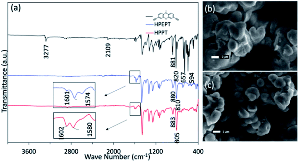 | ||
| Fig. 1 (a) FT-IR spectra of 1, HPPT and HPEPT. (b) SEM image of HPEPT. (c) SEM image of HPPT. | ||
The morphology of HPEPT and HPPT confirmed by scanning electron microscopy (SEM) images, indicating the relatively uniform micron-sized spheres (Fig. 1b and c). The thermal stabilities of HPEPT and HPPT were tested by using thermal gravimetric analysis (TGA) (Fig. S6a and b†). In Fig. S6a,† samples were heated from room temperature to 800 °C at a heating rate of 10 °C min−1 under nitrogen atmosphere. HPEPT and HPPT are thermally stable up to 372 °C and 421 °C, respectively (indicated by the 20% weight loss). TGAs tested in air indicated that the materials could be oxidized at about 200 °C and begin to decompose at about 400 °C (Fig. S6b†). The high thermal stability is crucial to the safety of rechargeable batteries. XRD patterns of HPEPT and HPPT establish the amorphous characters of HPEPT and HPPT (Fig. S7†).
As shown in Scheme 3, the redox activity of HPEPT and HPPT can be represented as N-substituted phenothiazine, whose redox mechanism involves a two successive one-electron oxidation process.15,34,35 The first stage oxidation of a neutral state leads to the formation of a radical cation (oxidized stage I), the second stage oxidation leads to the formation of oxidized stage II. These charges are compensated by electrolyte anions (PF6−).18
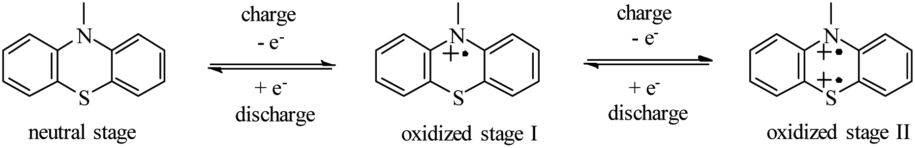 | ||
| Scheme 3 The electrochemical redox mechanism of the phenothiazine derivatives. | ||
The two-step reaction is also confirmed from the cyclic voltammetry (CV) measurement of HPEPT and HPPT. As shown in Fig. 2a and b (dashed line), HPEPT and HPPT exhibited the redox process of two electrons in the potential range of 3–4.7 V at the scan rate of 1 mV s−1 in the first cycle. As shown in Fig. 2a, HPEPT exhibited two oxidation peaks at 3.93 V and 4.54 V in the oxidation process and only one distinct reduction peak at 3.51 V in the reduction process. While HPPT have two oxidation peaks at 3.74 V and 4.37 V in the oxidation process, and together with two distinct reduction peaks at 3.52 V and 4.16 V in the reduction process (Fig. 2b). As can be seen from Fig. 2a and b, the redox processes of HPEPT and HPPT in this broad potential range are not completely reversible, possibly caused by the insufficient stability of electrolytes at high potential.17 Thereby, the electrochemical performances of HPEPT and HPPT were further investigated between 3 and 4.2 V/Li/Li+.
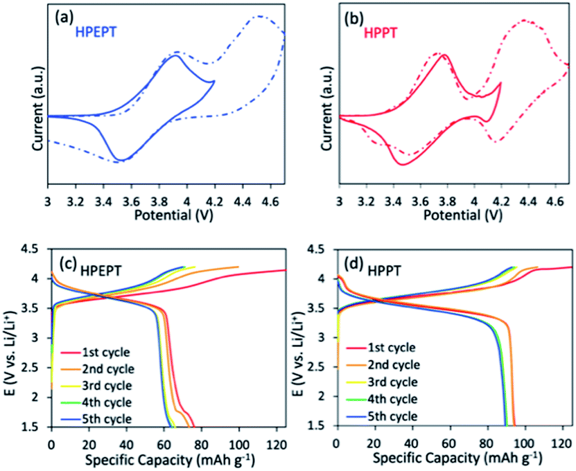 | ||
| Fig. 2 (a) Cyclic voltammograms of HPEPT in cell involves the first redox process (blue full line) in the voltage range of 3–4.2 V vs. Li/Li+ and the two redox process (blue dashed line) in the voltage range of 3–4.7 V vs. Li/Li+ at 1 mV s−1. (b) Cyclic voltammograms of HPPT in cell involves the first redox process (red full line) in the voltage range of 3–4.2 V vs. Li/Li+ and the two redox process (red dashed line) in the voltage range of 3–4.7 V vs. Li/Li+ at the scan rate of 1 mV s−1. (c) Discharge–charge curves of HPEPT with pre-activated 1st and 2nd cycles at 100 mA g−1 and 3rd, 4th, 5th cycles at 200 mA g−1. (d) Discharge–charge curves of HPPT with pre-activated 1st and 2nd cycles at 100 mA g−1 and 3rd, 4th, 5th cycles at 200 mA g−1. | ||
The CV studies of HPEPT and HPPT in the potential range 3–4.2 V at the scan rate of 1 mV s−1 are shown in Fig. 2a and b (full line). As shown in Fig. 2a, in the initial state, HPEPT has an anodic peak at 3.92 V and a cathodic peak at 3.52 V. The potential separation between the peaks is about 0.40 V. While HPPT has a slightly lower anodic peak at 3.78 V and a closely cathodic peak at 3.47 V (Fig. 2b). The narrower peak potential separation (about 0.31 V) indicates that HPPT has a lower electrode polarization than that of HPEPT during the electrochemical process under the same condition. This observation can be explained by the higher porous nature of HPPT, which allows the easier transportation of electrolyte ions and improves the electrochemical kinetics. The anodic and cathodic peaks of HPEPT and HPPT of the first three cycles are similar, indicating the robust stability and reversibility electrochemical performance of HPEPT and HPPT (see in Fig. S8†). While the potential separation between the redox peaks of each cycle becomes narrower with the progressing, indicating the activation processes in the beginning. The higher oxidation and reduction peaks of HPEPT than those of HPPT are possibly due to the relative electron-deficient CC groups in HPEPT. CC bond is sp-hybridized electron-withdrawing group that helps to increase the working voltage of the material.
The galvanostatic charge–discharge curves of HPEPT and HPPT in coin-type cells were measured at a current density of 200 mA g−1 and a potential window of 1.5–4.2 V with pre-activated 2 cycles at 100 mA g−1 (Fig. 2c–d). As shown in Fig. 2c, HPEPT displays an average discharge voltage plateau at about 3.65 V and a charge voltage plateau at about 3.81 V after 5 cycles. In comparison, the HPPT exhibits a relatively lower but longer discharge voltage plateau at about 3.48 V and a charge voltage plateau at about 3.76 V under the same conditions (Fig. 2d). The experimental results correspond with the CV curves.
The cycling behavior of HPEPT and HPPT at 200 mA g−1 is shown in Fig. 3a. Initial discharge capacity of HPPT is 90 mA h g−1 (87% of the theoretical capacity). While HPEPT shows relatively lower initial capacity of 66 mA h g−1 (76% of the theoretical capacity). The discharge capacities of HPPT could reach 76 mA h g−1 after 200 cycles and capacity retention of HPPT is 85%, which are much higher than those of HPEPT (43 mA h g−1 and 66%, respectively). The coulombic efficiency for HPPT reaches above 95% after 4 cycles, which is better than that of HPEPT (after 15 cycles reaches above 95%). The excellent cycling stabilities of HPEPT and HPPT could be attributed to the rigid robust structures of HPEPT and HPPT and their efficient inhibition of the volume expansion-shrinkage effect during charging–discharging processes. Furthermore, the hypercrosslinked polymers are insoluble in the organic electrolytes, which are also beneficial to the cycling capabilities. The relatively superior cycling stability of HPPT than that of HPEPT could be explained by its more efficient crosslinked archetecture, indicative by its higher specific surface area and more available channels in HPPT, which also accounts for their different percentages of active-site utilization.
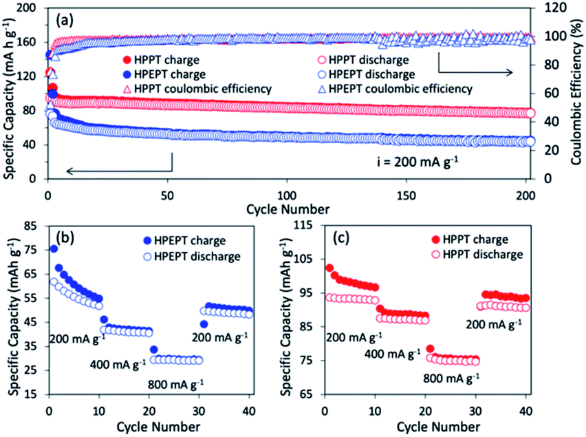 | ||
| Fig. 3 (a) Cycling performance of HPEPT and HPPT at a current density of 200 mA g−1. The cell was pre-activated 2 cycles at 100 mA g−1 before starting the measurements. (b) Rate capability of HPEPT. (c) Rate capability of HPPT. | ||
The rate performance of HPEPT and HPPT was tested at a current density of 200, 400 and 800 mA g−1. As compared to most other types of redox-active polymers with analogous structures, as shown in Fig. 3b and c, both polymers exhibited excellent rate performances even at high current density up to 800 mA g−1, ascribed to the conductive properties of the Fig. 3b and c show the capacity of HPEPT and HPPT decreases as current density increases. The specific capacity of HPEPT was 52, 40, 29 mA h g−1 at 200, 400, and 800 mA g−1 after 10 cycles, whereas HPPT presents superior reversible capacities of 93, 87, and 75 mA h g−1 at 200, 400, and 800 mA g−1. The specific capacity of HPPT material still reached 91 mA h g−1 when returned to 200 mA g−1 with 98% capacity retention. This result demonstrates that HPPT electrodes possess high rate capability than that of HEPPT. Again, this result could be attributed to the relative higher porosity and open transportation channels of HPPT.
Conclusions
In summary, we successfully synthesized two novel insoluble rigid hypercrosslinked phenothiazine-functionalized polymers (HPEPT and HPPT) and studied their applications as organic cathode materials of lithium ion batteries. These phenothiazine-based p-type polymers, HPEPT and HPPT, inherit the excellent electrochemical properties from their parent monomers, and possess reversible redox activity with high discharge potentials at 3.65 and 3.48 V, respectively. More importantly, the porous HPPT obtained with pretty high specific surface area (SBET: 452 m2 g−1) still maintains high electric conductivity as the linear phenothiazine-based polymers have, enabling the material with high redox kinetics and efficient active-site utilization (87% of the theoretical capacity) without any further modification. Moreover, the porous hypercrosslinked polymers with rigid structure could effectively inhibit volume expansion-shrinkage effect of the p-type electrode materials, and endow the improved cycling stability. The discovery herein opens a new direction for development of novel organic electrode materials.Conflicts of interest
There are no conflicts to declare.Acknowledgements
H. Y. thanks the financial supports from Science and Technology Commission of Shanghai Municipality (19DZ2271100), and the Program for Professor of Special Appointment (Eastern Scholar) at Shanghai Institutions of Higher Learning. Y. D. thanks National Natural Science Foundation of China (21805134), Natural Science Foundation of Jiangsu Province, China (BK20191363), Science and Technology Innovation Project for Overseas Students from Nanjing City, and Start-up Grant No. 39837141 from NJTECH. The authors thank Prof. Honghua Ge's group for the assistance of FTIR measurements.Notes and references
- M. Armand and J.-M. Tarascon, Nature, 2008, 451, 652–657 CrossRef CAS PubMed.
- P. L. Taberna, S. Mitra, P. Poizot, P. Simon and J. M. Tarascon, Nat. Mater., 2006, 5, 567–573 CrossRef CAS PubMed.
- V. Etacheri, R. Marom, R. Elazari, G. Salitra and D. Aurbach, Energy Environ. Sci., 2011, 4, 3243–3262 RSC.
- S. Muench, A. Wild, C. Friebe, B. Haupler, T. Janoschka and U. S. Schubert, Chem. Rev., 2016, 116, 9438–9484 CrossRef CAS PubMed.
- M. S. Whittingham, Chem. Rev., 2004, 104, 4271–4301 CrossRef CAS PubMed.
- S. Zhang, W. Huang, P. Hu, C. Huang, C. Shang, C. Zhang, R. Yang and G. Cui, J. Mater. Chem. A, 2015, 3, 1896–1901 RSC.
- B. Dunn, H. Kamath and J.-M. Tarascon, Science, 2011, 334, 928–935 CrossRef CAS PubMed.
- Y. Zhao, Y. Ding, Y. Li, L. Peng, H. R. Byon, J. B. Goodenough and G. Yu, Chem. Soc. Rev., 2015, 44, 7968–7996 RSC.
- J. Winsberg, T. Hagemann, T. Janoschka, M. D. Hager and U. S. Schubert, Angew. Chem., Int. Ed., 2017, 56, 686–711 CrossRef CAS PubMed.
- R. Gracia and D. Mecerreyes, Polym. Chem., 2013, 4, 2206–2214 RSC.
- Q. He, C. Zhang, X. Li, X. Wang, P. Mu and J. Jiang, Acta Chim. Sin., 2018, 76, 202–208 CrossRef CAS.
- K. Pirnat, J. Bitenc, A. Vizintin, A. Krajnc and E. Tchernychova, Chem. Mater., 2018, 30, 5726–5732 CrossRef CAS.
- X. Liu and A. Du, Chin. Polym. Bull., 2017, 8, 78–85 CrossRef.
- Y. Zhang, J. Wang and S. N. Riduan, J. Mater. Chem. A, 2016, 4, 14902–14914 RSC.
- M. Kolek, F. Otteny, P. Schmidt, C. Mück-Lichtenfeld, C. Einholz, J. Becking, E. Schleicher, M. Winter, P. Bieker and B. Esserb, Energy Environ. Sci., 2017, 10, 2334–2341 RSC.
- C. Zhang, Z. Niu, S. Peng, Y. Ding, L. Zhang, X. Guo, Y. Zhao and G. Yu, Adv. Mater., 2019, 31, 1901052 CrossRef PubMed.
- T. Godet-Bar, J. C. Lepretre, O. Le Bacq, J. Y. Sanchez, A. Deronzier and A. Pasturel, Phys. Chem. Chem. Phys., 2015, 17, 25283–25296 RSC.
- R. Guilmin, F. Alloin, F. Molton and J.-C. Leprêtre, Electrochim. Acta, 2017, 232, 182–191 CrossRef CAS.
- S. Ergun, C. F. Elliott, A. P. Kaur, S. R. Parkin and S. A. Odom, Chem. Commun., 2014, 50, 5339–5341 RSC.
- M. Lee, J. Hong, B. Lee, K. Ku, S. Lee, C. B. Park and K. Kang, Green Chem., 2017, 19, 2980–2985 RSC.
- T. Shimizu, K. Yamamoto, P. Pandit, H. Yoshikawa and S. Higashibayashi, Sci. Rep., 2018, 8, 579 CrossRef PubMed.
- F. Otteny, M. Kolek, J. Becking, M. Winter, P. Bieker and B. Esser, Adv. Energy Mater., 2018, 8, 1802151 CrossRef.
- Y. Zhang, S. N. Riduan and J. Wang, Chem.–Eur. J., 2017, 23, 16419–16431 CrossRef CAS PubMed.
- Y. Zhong, Y. Yang, Y. Shen, W. Xu, Q. Wang, A. L. Connor, X. Zhou, L. He, X. C. Zeng, Z. Shao, Z. L. Lu and B. Gong, J. Am. Chem. Soc., 2017, 139, 15950–15957 CrossRef CAS PubMed.
- C. Su, H. He, L. Xu, K. Zhao, C. Zheng and C. Zhang, J. Mater. Chem. A, 2017, 5, 2701–2709 RSC.
- J. Xie, W. Chen, G. Long, W. Gao, Z. J. Xu, M. Liu and Q. Zhang, J. Mater. Chem. A, 2018, 6, 12985–12991 RSC.
- R. Krishna, V. Kurshev and L. Kevan, Phys. Chem. Chem. Phys., 1999, 1, 2833–2839 RSC.
- R. M. Pearson, C. H. Lim, B. G. McCarthy, C. B. Musgrave and G. M. Miyake, J. Am. Chem. Soc., 2016, 138, 11399–11407 CrossRef CAS PubMed.
- A. Arnanz, C. Moreno, M.-L. Marcos, J. González-Velasco and S. Delgado, Eur. J. Inorg. Chem., 2007, 2007, 5215–5225 CrossRef.
- Q. Chen, Y. Ma, C. Wang and Y. Shen, Chin. J. Org. Chem., 2012, 32, 1526–1532 CrossRef CAS.
- P. K. Mandali and D. K. Chand, Catal. Commun., 2014, 47, 40–44 CrossRef CAS.
- Y. Zhu, H. Yang, Y. Jin and W. Zhang, Chem. Mater., 2013, 25, 3718–3723 CrossRef CAS.
- M. H. Weston, O. K. Farha, B. G. Hauser, J. T. Hupp and S. T. Nguyen, Chem. Mater., 2012, 24, 1292–1296 CrossRef CAS.
- A. Golriz, T. Suga, H. Nishide and R. B. a. J. Gutmann, RSC Adv., 2015, 5, 22947–22950 RSC.
- P. Acker, L. Rzesny, C. F. N. Marchiori, C. M. Araujo and B. Esser, Adv. Funct. Mater., 2019, 29, 1906436 CrossRef CAS.
Footnote |
| † Electronic supplementary information (ESI) available. See DOI: 10.1039/d0ra01312a |
| This journal is © The Royal Society of Chemistry 2020 |