
 Open Access Article
 This Open Access Article is licensed under a Creative Commons Attribution-Non Commercial 3.0 Unported Licence
Raman spectroscopy-in situ characterization of reversibly intercalated oxygen vacancies in α-MoO3†
Isaías de Castro Silva,
Alice Cosenza Reinaldo,
Fernando Aparecido Sigoli and
Italo Odone Mazali*
and
Italo Odone Mazali*
Laboratory of Functional Materials– Institute of Chemistry, University of Campinas – UNICAMP, P. O. Box 6154, 13083-970, Campinas, SP, Brazil. E-mail: mazali@unicamp.br
First published on 14th May 2020
Abstract
This work reports on the in situ strategy to reversibly generate or suppress oxygen vacancies on α-MoO3 which were probed by Raman spectroscopy. Reversible changes in two features of the α-MoO3 Raman spectrum could be correlated to the generation of oxygen vacancies: displacement of the Tb band frequency and the intensity decrease of the symmetrical stretching (νs) band. These two features could be used to qualitatively describe oxygen vacancies. Raman results also indicate that oxygen vacancies are located in the interlayer region of the α-MoO3 lattice. This observation is corroborated by in situ X-ray diffraction, which also indicates the absence of nonstoichiometric phase transitions.
1. Introduction
Molybdenum–oxygen systems include a series of nonstoichiometric solids, in which the oxygen/molybdenum ratio varies between 3 (MoVIO3) and 2 (MoIVO2).1 Some values of the oxygen/molybdenum ratio have nonstoichiometric crystalline phases1 that are well characterized by X-ray diffraction (XRD) and can be classified, according to their crystalline structure as derived from α-MoO3, ReO3 or W18O49 structures.1 Although the changes in the oxygen/molybdenum ratio in these oxides are almost always followed by nonstoichiometric phase transitions,2 the presence of oxygen vacancies is an important feature to take into account when molybdenum oxides are applied as catalysts,3,4 anode materials for lithium-ion batteries,5 gas sensors,6,7 electrochromic devices,8 and surface-enhanced Raman spectroscopy substrates.9Raman spectroscopy is another tool to characterize nonstoichiometric molybdenum oxides. The α-MoO3 Raman spectrum is sensitive to particle sizes and the generation of oxygen vacancies.3,10 The intensity of the symmetrical stretching (νs) band near 820 cm−1 depends on the presence of oxygen vacancies and the intensity ratio of the two bands between 280 and 300 cm−1 can be used to estimate the oxygen/molybdenum ratio in the range from 2.94 to 3.3 However, if the latter bands are convoluted this methodology cannot be applied.
This work reports on the observation of changes in the Raman spectrum of α-MoO3 submitted to an in situ gas–solid reaction capable of reversibly generate or suppress oxygen vacancies. Nonstoichiometric phase transition was not observed during experiments, as indicated by in situ XRD measurements, allowing a qualitative evaluation of oxygen vacancies by Raman spectroscopy.
2. Experimental section
2.1. Synthesis
The synthesis procedure was adapted from a previous report.11 An amount of 7 mL of nitric acid 3 mol L−1 was added to a solution consisting of 0.4900 g of (NH4)6Mo7O24·4H2O dissolved in 13 mL of deionized water. The final solution was stirred for 5 min, open to the air, before being transferred to a 50 mL poly(tetrafluoroethene)-lined stainless-steel autoclave. The autoclave was held at 180 °C for 20 h. After cooling, the obtained white solid was filtered and washed several times with ethanol and deionized water and dried at 60 °C for 12 h.2.2. Characterization
A Linkam TS1500 stage, coupled with the Linkam T95-HT controller, was used to in situ control temperature (resolution of 1 °C) and atmosphere In a manner similar to XRD with in situ control of temperature and atmosphere, the atmosphere was alternated between 2% H2/Ar and O2 at 400 °C (30 min of exposure in each one), always with an N2 purge flow (5 min) between atmosphere changes. The flow rates were adjusted to 150 mL min−1, and the sample was always heated under O2, at the rate of 20 °C min−1. A total number of three cycles of atmosphere change was carried out at 400 °C.
3. Results and discussion
Peaks observed in the diffractogram obtained at room temperature are indexed to the α-MoO3 orthorhombic phase and β-MoO3 monoclinic phase (Fig. 1). The diffractogram is dominated by (0k0) peaks of the α-MoO3 phase, were “k” stands for an even number, which is a consequence of preferential growth of the crystallites in the [010] direction, or “b” axis.4,15,16. A complete indexation of the observed peaks at room temperature is found in ESI, Table S1.†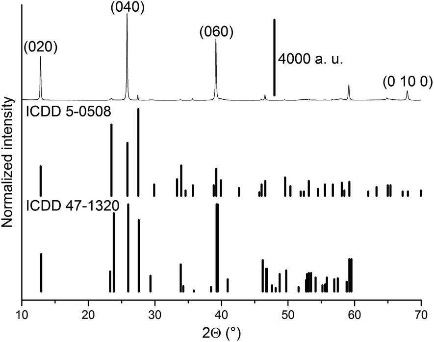 | ||
| Fig. 1 Diffractogram obtained for MoO3 sample at 22 °C under 20% O2/He. The MoO3 files ICDD 5-0508 (α-MoO3) and 47-1320 (β-MoO3) are shown as vertical lines. | ||
One can see in SEM images that the sample is constituted of needle-like crystals (Fig. 2), with a preferential direction of growth, as pointed out by XRD measurement.
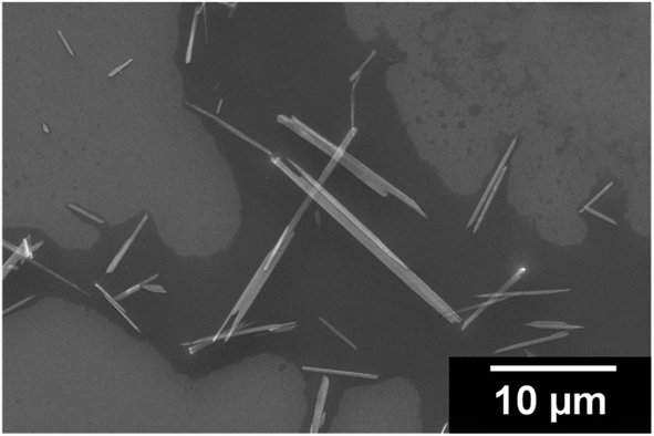 | ||
| Fig. 2 SEM image of MoO3 crystals. | ||
Particle size counting shows that MoO3 crystals have an average size of 4696 nm in length and 386 nm in width, and the mode size range (ca. 30%) being 719–5000 nm in length and 250–375 nm in width (Fig. 3).
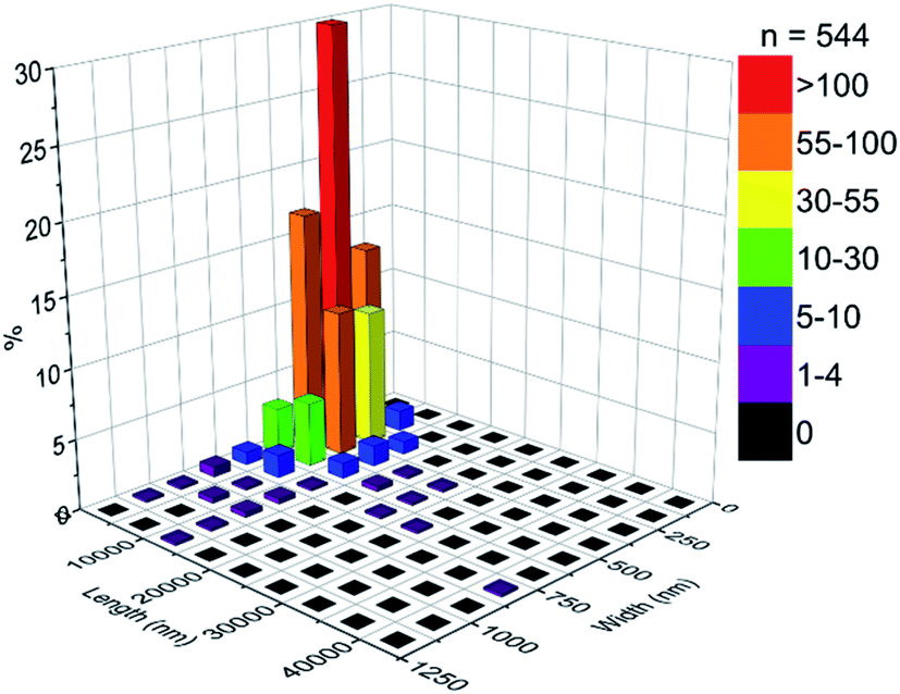 | ||
| Fig. 3 Particle size distribution of MoO3 crystals. | ||
The observed bands in the Raman spectrum (Fig. 4) are listed in Table 1 and are attributed to the α-MoO3 orthorhombic phase. This solid can be described as a layered structure composed of linear chains of [MoO3] unities. If it is considered that the molybdenum ions have a distorted tetrahedral coordination, two oxygen ions are single coordinated to a molybdenum ion and are called terminal oxygens (Mo![[double bond, length as m-dash]](https://www.rsc.org/images/entities/char_e001.gif) O). The other one is called bridging oxygen, represented as Mo–O, and is coordinated to two molybdenum ions.17
O). The other one is called bridging oxygen, represented as Mo–O, and is coordinated to two molybdenum ions.17
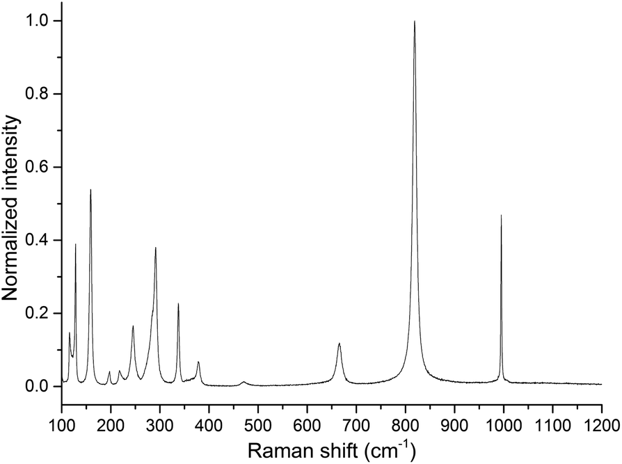 | ||
| Fig. 4 Raman spectrum of MoO3 sample obtained at 23 °C under static air inside the heating stage. | ||
| Band frequency (cm−1) | Representation17 | Attribution17 |
|---|---|---|
| 116 | B2g | Translational chain mode along “c” direction (Tc) |
| 128 | B3g | Translational chain mode along “c” direction (Tc) |
| 159 | Ag/B1g | Translational chain mode along “b” direction (Tb) |
| 197 | B2g | τ OMoO |
| 218 | Ag | Rotational chain mode along “c” direction (Rc) |
| 246 | B3g | τ OMoO |
| 291 | B3g | ω OMoO |
| 338 | Ag/B1g | δ O–Mo–O |
| 379 | B1g | δ OMoO (scissoring) |
| 471 | Ag/B1g | ν, δ O–Mo–O |
| 666 | B2g/B3g | ν O–Mo–O |
| 819 | Ag/B1g | νs OMoO |
| 995 | Ag | νas OMoO |
The band at 285 cm−1, attributed to a B2g wagging mode of terminal oxygens, is observed as a shoulder of the band at 291 cm−1. The intensity ratio of the bands at 285 and 291 cm−1 may be used to determine the oxygen/molybdenum ratio, in the range from 2.94 to 3.3 However, as one can observe from the Raman spectrum (Fig. 4), the precise determination of intensities ratio requires a comprehensive methodology.
Raman spectra with in situ control of temperature and atmosphere are shown in Fig. 5 and 6. A displacement of Tb (Ag/B1g) Raman band to lower frequencies was observed upon heating, a phenomenon attributed to phonon decay,18 lattice expansion19 and generation of oxygen vacancies (ESI, Fig. S1†).
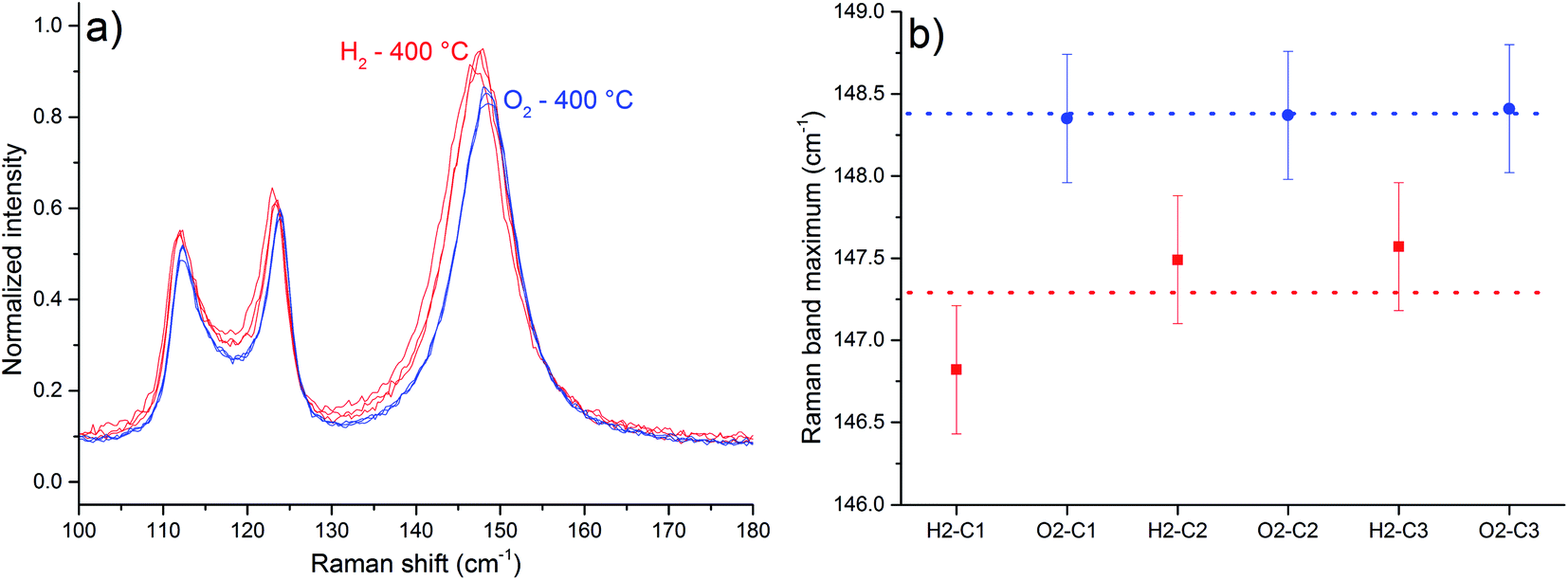 | ||
| Fig. 5 Part of the Raman spectra obtained at 400 °C for MoO3 sample, normalized in intensity of νs band (a). The average displacement observed for the Tb band under H2 was 1.09 cm−1 (b). The blue ones were obtained after O2 exposure, and the red ones were obtained after H2 exposure. The bars represent spectral resolution – 0.39 cm−1. | ||
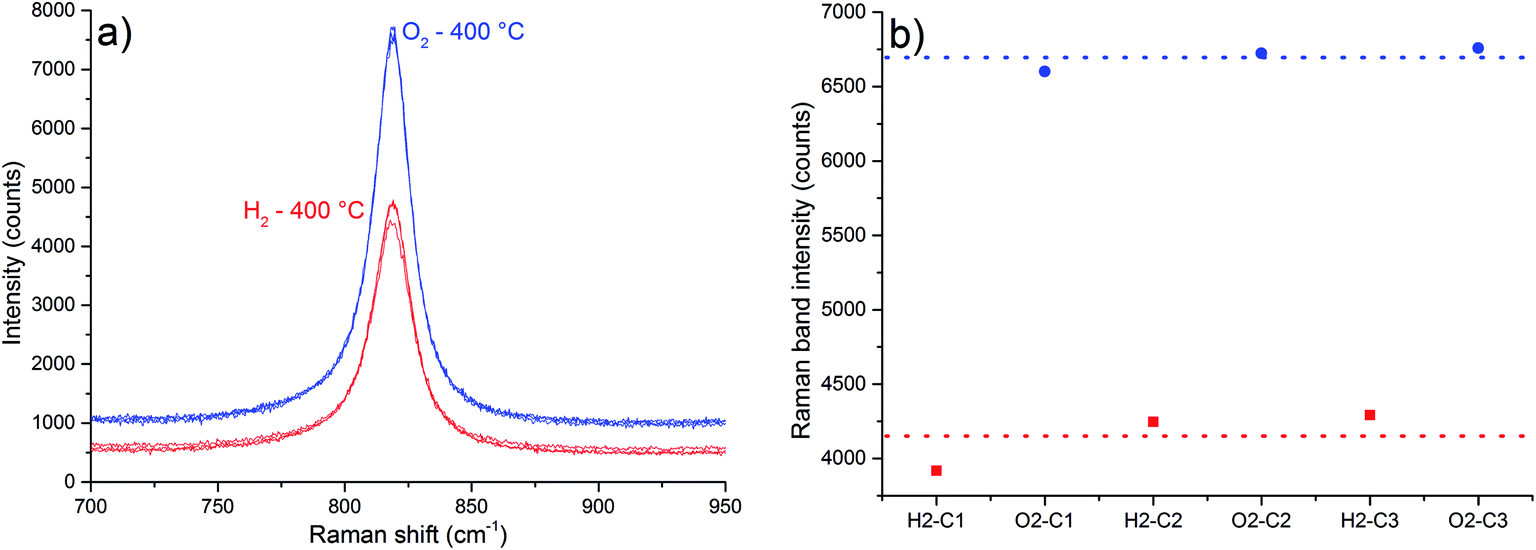 | ||
| Fig. 6 Part of the Raman spectra obtained at 400 °C for the MoO3 sample, comprising the νs band (a). The average decrease in intensity observed under H2 was approximately 38% (b). The blue ones were obtained after O2 exposure, and the red ones were obtained after H2 exposure. | ||
As in situ Raman results reveal, the exposure to the H2-containing atmosphere at 400 °C also causes a displacement of the Tb Raman band (Fig. 5). Band maxima wavenumber were obtained from the most intense spectral point. The average displacement, calculated considering the values of Tb band maxima obtained from the 3 spectra in each atmosphere, was 1.09 cm−1, observed between the spectra under H2 in relation to spectra under O2 (Fig. 5 b). A displacement to lower frequency values of α-MoO3 Raman bands is expected if the interaction between the layers of the crystal is weakened, in a manner that the observed Raman band frequencies should resemble more a single layer than the whole crystal.20 This is attributed to the generation of oxygen vacancies and water release,21 as shown in eqn (1).
| MoO3 + yH2 → MoO3−y + yH2O | (1) |
A displacement to lower frequencies of the Tb band was observed when α-MoO3 was heated to 375 °C under reduced pressure of 10−1 Pa for 10 h.22 Moreover, the generation and suppression of oxygen vacancies is a reversible process at 400 °C, since the Tb Raman band exhibit roughly the same frequency after one cycle of atmosphere change.
The intensity ratio of Tc bands can be used to estimate α-MoO3 particle sizes.3,10 However, in one reference the ratio I(B3g)/I(B2g) increases as the size diminishes,10 and in the other, the ratio I(B3g)/I(B2g) decreases as the particle size diminishes.3 However, just the first reference shows the Raman spectra, therefore we expect the increase in the I(B3g)/I(B2g) ratio as the size diminishes. Based on the latter premise, it is not possible to infer any change in the particle sizes as a function of thermal treatments (Table 2).
| I123(B3g)/I112(B2g) | I123(B3g)/I112(B2g) | ||
|---|---|---|---|
| H2–C1 | 1.225 | O2–C1 | 1.244 |
| H2–C2 | 1.125 | O2–C2 | 1.178 |
| H2–C3 | 1.138 | O2–C3 | 1.196 |
The band at 819 cm−1, attributed to the symmetric stretching of the terminal oxygens (νs band), is sensitive to oxygen vacancies.3 An intensity increase of this band was observed in situ after reacting nonstoichiometric α-MoO3 with propene and O2, a consequence of oxygen vacancies suppression.3 One attempt to explain this fact is based on the following aspects:3 when oxygen vacancies are generated, there is also the formation of [Mo5+O5] sites. An electronic transition from this site to a normal site of the crystal represented as [Mo5+O5]-[Mo6+O6] → [Mo6+O5]-[Mo5+O6], is called intervalence charge transfer (IVCT). According to Dieterle et al.,3 the energy of this IVCT transition would be near the energy of the excitation laser (633 nm – 1.96 eV), based on the deconvolution of the diffuse reflectance absorption spectra, and it is supposed to increase in energy as more oxygen vacancies are present in α-MoO3 lattice.3 Therefore, a resonant Raman-like effect would be observed when oxygen vacancies are generated. Once it is considered the Stokes branch of the Raman scattering, it is possible to occur the reabsorption of the scattered light, affecting the intensity of the Raman spectrum. The most reabsorbed scattered radiation would be the one with energy close to the excitation laser. In other words, it is expected that the bands with lower wavenumbers would present the highest values of intensity decrease. Supposing that the maximum of the IVCT transition varies with stoichiometry, and the incident radiation does not, a specific value of the IVCT transition energy would result in the most intense Raman spectrum, which implies that a specific value of nonstoichiometric degree of the α-MoO3 would result in the most intense Raman spectrum.
However, the described proposal3 is based on the intensity of the νs band observed in different samples, with different particle sizes. The size of the particles may affect the intensity of the Raman spectrum.23–34 Yet, according Dieterle et al.,3 the energy value of the IVCT transition is calculated based on the deconvolution of the diffuse reflectance absorption spectrum, rather than a clearer spectral feature. In our case Raman spectra were obtained in situ, so the spectra are obtained from the same sample point. As the results in Table 2 suggest, there is no change in particle size during experiments. The highest values of intensity decrease were observed for the bands more distant in energy to the excitation radiation (Table 3), which is contrary to the described proposal.3 In addition, Mestl et al.;10 have found that the intensity decrease of Raman bands is independent of the excitation energy in the range from 458 nm to 622 nm.10
| Band frequency at 400 °C (cm−1) | Average intensity under O2 (counts) | Average intensity under H2 (counts) | Decrease in intensity (%) |
|---|---|---|---|
| 112 | 3068 | 2120 | 30.9 |
| 123 | 3697 | 2461 | 33.44 |
| 148 | 5586 | 3868 | 30.75 |
| 194 | 592 | 468 | 20.9 |
| 212 | 432 | 389 | 10 |
| 238 | 1042 | 782 | 25.0 |
| 285 | 2973 | 2035 | 31.6 |
| 335 | 1461 | 1000 | 31.5 |
| 374 | 392 | 321 | 18 |
| 664 | 648 | 414 | 36.1 |
| 819 | 6695 | 4152 | 37.98 |
| 992 | 2784 | 1722 | 38.17 |
If the displacement of the Tb Raman band is plotted against the decrease in intensity of the νs band, a linear relationship is obtained (Fig. 7). This fact suggests that both these observations are related to the same effect, the generation of oxygen vacancies in α-MoO3, and could be considered to evaluate its oxygen vacancies. Contrary to the previous report3 which stated that a determined value of nonstoichiometry may lead to the most intense νs band, this correlation suggests that the most intense νs band is observed in the sample with the highest oxygen/molybdenum ratio, the stoichiometric α-MoO3.
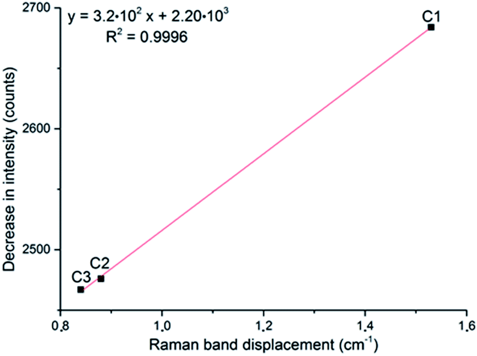 | ||
| Fig. 7 Correlation of the displacement of the Tb band frequency and the decrease in intensity of the νs band, at 819 cm−1, after exposure to H2 during three cycles (C#). | ||
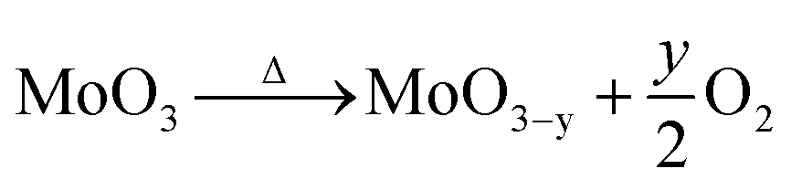
It was observed a loss of mass upon heating, due to the formation of oxygen vacancies,22 according to eqn (2).
 | (2) |
If it is considered that the starting dried sample was composed of stoichiometric MoO3, the loss of mass upon heating resulted in a variation of the nonstoichiometric degree of 0.039 (MoO2.961). This value of stoichiometry is not compatible with any other crystalline phase of the molybdenum–oxygen system.1
The calculated OSC value of 35 ± 3 μmol (O2) g−1, at 400 °C, were obtained from the OSC curve in Fig. 8.
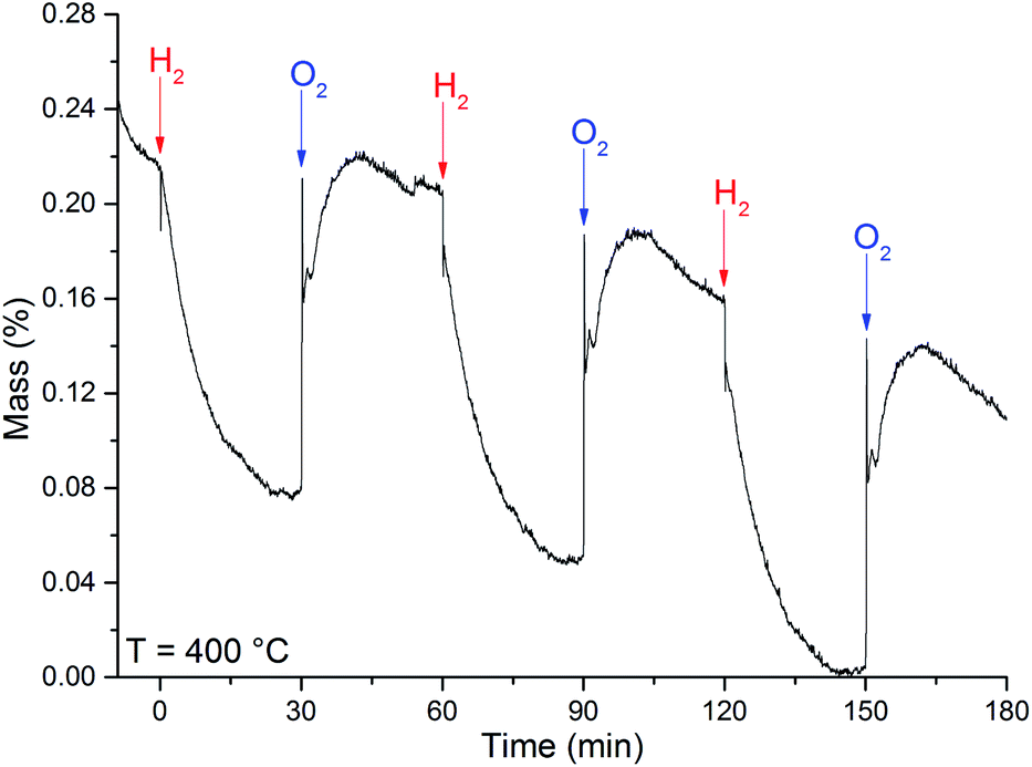 | ||
| Fig. 8 OSC curve obtained at the temperature of 400 °C for the MoO3 sample. The arrows indicate when the referred gas was introduced in the system. | ||
The loss of mass under H2 exposure is attributed to the formation of water and oxygen vacancies (eqn (1)). These vacancies are suppressed under O2 exposure. The reincorporation of oxygen ions in the MoO3 lattice is accompanied by a gain of mass. Due to the adsorption of gases, it is not possible to obtain any quantitative measurement of the nonstoichiometric degree. However, if we consider that the difference in mass is solely due to generation and suppression of oxygen vacancies, the variation of the nonstoichiometric degree, achieved after H2 exposure at 400 °C, can be estimated to be 0.010 ± 0.002 (MoO2.951). This value of stoichiometry is not compatible with any other crystalline phase of the molybdenum–oxygen system.1
Part of the diffractograms with in situ control of temperature and atmosphere, illustrating the peaks (110), (040) and (021) of the α-MoO3 phase, are shown in Fig. 9.
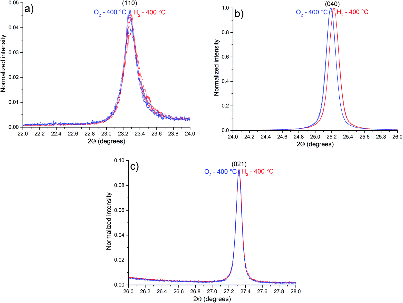 | ||
| Fig. 9 Parts of the diffractograms of α-MoO3 planes: (a) (110); (b) (040); and (c) (021), obtained at 400 °C. The blue ones were obtained after O2 exposure and the red ones were obtained after H2 exposure. | ||
Compared to the diffractogram of Fig. 1, the diffraction peaks observed in Fig. 9 are shifted to minor values of 2θ due to thermal expansion of the lattice. As pointed out by OSC results, no phase transition was observed during experiments (Fig. S2†). Table 4 lists the observed planes that are shifted after exposure to H2 at 400 °C (Fig. S3†).
| Plane | Average 2θ under H2 (°) | Average 2θ under O2 (°) | Difference in 2θ (H2–O2) (°) |
|---|---|---|---|
| 020 | 12.531 | 12.515 | 0.016 |
| 040 | 25.227 | 25.187 | 0.040 |
| 041 | 35.225 | 35.205 | 0.020 |
| 060 | 38.251 | 38.198 | 0.053 |
| 210 | 45.759 | 45.739 | 0.020 |
| 002 | 49.531 | 49.543 | −0.012 |
| 211 | 51.815 | 51.745 | 0.060 |
| 171 | 57.005 | 56.955 | 0.050 |
| 081 | 57.963 | 57.907 | 0.056 |
| 190 | 63.793 | 63.728 | 0.065 |
| 062 | 64.263 | 64.244 | 0.019 |
| 0 10 0 | 66.213 | 66.141 | 0.072 |
| * | 69.361 | 69.275 | 0.086 |
Some diffraction peaks of the α-MoO3 phase are shifted to higher values of 2θ after H2 exposure due to a lattice contraction after exposure to H2, a consequence of the oxygen vacancies generation. The reason for the α-MoO3 (0k0) peaks shift to higher values of 2θ (Table 4), in “b” direction, is the location of the oxygen vacancies in the interlayer region, as pointed out by in situ Raman results. The terminal oxygens in the interlayer region have the lowest calculated energy value of oxygen vacancy formation.35,36 However, the diffraction peak attributed to (002) plane is shifted to lower values of 2θ after H2 exposure, indicating an expansion of the lattice in the “c” direction. These observations are in contrast with a previous report,3 when an expansion in the “b” direction and a contraction in the “c” direction were reported, suggesting that oxygen vacancies tend to replace bridging oxygens. However, the results here obtained indicate that oxygen vacancies tend to accumulate in the interlayer region, replacing terminal oxygens, leading to the decrease in the layer distance, and a contraction in “b” direction. As a consequence, Raman bands are shifted to lower frequencies, resembling more the calculated spectrum of a single layer than the spectrum of the crystal.21
4. Conclusion
After submitting MoO3 need-like crystals to an in situ strategy to reversibly generate or suppress oxygen vacancies, it was possible to observe reversible changes in two α-MoO3 Raman features: the displacement of Tb band and the decrease in intensity of the νs band. The displacement of the Tb band is attributed to the weakening of α-MoO3 layers interaction, probably due to the location of oxygen vacancies in the interlayer region. XRD results corroborate the location of oxygen vacancies in the interlayer region, as the small value of vacancy formation energy is observed in this region. The decrease in intensity of the νs band was not possible to be attributed, but the proposal of a resonant Raman-like effect was contested. Based on that, Raman spectroscopy can provide two distinct manners to qualitative probe oxygen vacancies in α-MoO3. No nonstoichiometric phase transition was observed by XRD or OSC results, indicating that the observations were, in fact, derived from the generation of oxygen vacancies in the α-MoO3 structure.Conflicts of interest
There are no conflicts to declare.Acknowledgements
The authors gratefully acknowledge CNPq and FAPESP for the financial support. Contributions from Brazilian Synchrotron Light Laboratory (LNLS/CNPEM, Brazil - Proposal 20171016) and Multiuser Laboratory of Advanced Optical Spectroscopy (LMEOA/IQ-UNICAMP) for XRD and Raman measurements, respectively, are also gratefully acknowledged. This is a contribution of the National Institute of Science and Technology in Complex Functional Materials (CNPq-MCT/FAPESP).References
- L. Kihlborg, in Nonstoichiometric compounds, ed. R. Ward, American Chemical Society, 1963, pp. 37–45 Search PubMed.
- P. L. Gai, Philos. Mag. A, 1981, 43, 841–855 CrossRef CAS.
- M. Dieterle, G. Weinberg and G. Mestl, Phys. Chem. Chem. Phys., 2002, 4, 812–821 RSC.
- J. González, J. A. Wang, L. Chen, M. Manríquez, J. Salmones, R. Limas and U. Arellano, J. Solid State Chem., 2018, 263, 100–114 CrossRef.
- D. Wu, R. Shen, R. Yang, W. Ji, M. Jiang, W. Ding and L. Peng, Sci. Rep., 2017, 7, 44697 CrossRef CAS PubMed.
- M. M. Y. A. Alsaif, M. R. Field, B. J. Murdoch, T. Daeneke, K. Latham, A. F. Chrimes, A. S. Zoolfakar, S. P. Russo, J. Z. Ou and K. Kalantar-zadeh, Nanoscale, 2014, 6, 12780–12791 RSC.
- N. Illyaskutty, S. Sreedhar, G. S. Kumar, H. Kohler, M. Schwotzer, C. Natzeck and V. P. M. Pillai, Nanoscale, 2014, 6, 13882–13894 RSC.
- B. Dasgupta, Y. Ren, L. M. Wong, L. Kong, E. S. Tok, W. K. Chim and S. Y. Chiam, J. Phys. Chem. C, 2015, 119, 10592–10601 CrossRef CAS.
- H. Wu, H. Wang and G. Li, Analyst, 2017, 142, 326–335 RSC.
- G. Mestl, T. K. K. Srinivasan and H. Knözinger, Langmuir, 1995, 11, 3795–3804 CrossRef CAS.
- Y. Chen, C. Lu, L. Xu, Y. Ma, W. Hou and J.-J. Zhu, CrystEngComm, 2010, 12, 3740–3747 RSC.
- L. Ilieva, P. Petrova, G. Pantaleo, R. Zanella, L. F. Liotta, V. Georgiev, S. Boghosian, Z. Kaszkur, J. W. Sobczak, W. Lisowski, A. M. Venezia and T. Tabakova, Appl. Catal., B, 2016, 188, 154–168 CrossRef CAS.
- C. Andriopoulou, A. Trimpalis, K. C. Petallidou, A. Sgoura, A. M. Efstathiou and S. Boghosian, J. Phys. Chem. C, 2017, 121, 7931–7943 CrossRef.
- I. C. Silva, F. A. Sigoli and I. O. Mazali, J. Phys. Chem. C, 2017, 121, 12928–12935 CrossRef CAS.
- W. Thöni, P. Gai and P. B. Hirsch, J. Less-Common Met., 1977, 54, 263–271 CrossRef.
- M. Epifani, P. Imperatori, L. Mirenghi, M. Schioppa and P. Siciliano, Chem. Mater., 2004, 16, 5495–5501 CrossRef CAS.
- M. A. Py, P. E. Schmid and J. T. Vallin, Nuovo Cimento B, 1977, 38, 271–279 CrossRef.
- M. Balkanski, R. F. Wallis and E. Haro, Phys. Rev. B: Condens. Matter Mater. Phys., 1983, 28, 1928–1934 CrossRef CAS.
- J. E. Spanier, R. D. Robinson, F. Zhang, S.-W. Chan and I. P. Herman, Phys. Rev. B: Condens. Matter Mater. Phys., 2001, 64, 245407 CrossRef.
- M. A. Py and K. Maschke, Physica B, 1981, 105, 370–374 CrossRef CAS.
- W. E. Garner, J. Chem. Soc., 1947, 1239–1244 RSC.
- G. Mestl, P. Ruiz, B. Delmon and H. Knözinger, J. Phys. Chem., 1994, 98, 11269–11275 CrossRef CAS.
- M. V. Pellow-Jarman, P. J. Hendra and R. J. Lehnert, Vib. Spectrosc., 1996, 12, 257–261 CrossRef CAS.
- H. Wang, C. K. Mann and T. J. Vickers, Appl. Spectrosc., 2002, 56, 1538–1544 CrossRef CAS.
- C. H. Chio, S. K. Sharma, P. G. Lucey and D. W. Muenow, Appl. Spectrosc., 2003, 57, 774–783 CrossRef CAS PubMed.
- Y. Hu, H. Wikström, S. R. Byrn and L. S. Taylor, Appl. Spectrosc., 2006, 60, 977–984 CrossRef CAS PubMed.
- Z.-P. Chen, L.-M. Li, J.-W. Ji, A. Nordon, D. Littlejohn, J. Yang, J. Zhang and R.-Q. Yu, Anal. Chem., 2012, 84, 4088–4094 CrossRef CAS PubMed.
- N. Townshend, A. Nordon, D. Littlejohn, J. Andrews and P. Dallin, Anal. Chem., 2012, 84, 4665–4670 CrossRef CAS PubMed.
- P. Allan, L. J. Bellamy, A. Nordon, D. Littlejohn, J. Andrews and P. Dallin, J. Pharmaceut. Biomed. Anal., 2013, 76, 28–35 CrossRef CAS PubMed.
- F. Foucher, G. Lopez-Reyes, N. Bost, F. Rull-Perez, P. Rüßmann and F. Westall, J. Raman Spectrosc., 2013, 44, 916–925 CrossRef CAS.
- A. Sparén, M. Hartman, M. Fransson, J. Johansson and O. Svensson, Appl. Spectrosc., 2015, 69, 580–589 CrossRef PubMed.
- P. Kristova, L. J. Hopkinson and K. J. Rutt, J. Phys. Chem. A, 2015, 119, 4891–4897 CrossRef CAS PubMed.
- P. K. Duy, S. Chun and H. Chung, Anal. Chem., 2017, 89, 11937–11943 CrossRef CAS PubMed.
- D. A. Gómez, J. Coello and S. Maspoch, Vib. Spectrosc., 2019, 100, 48–56 CrossRef.
- R. Coquet and D. J. Willock, Phys. Chem. Chem. Phys., 2005, 7, 3819–3828 RSC.
- K. Inzani, M. Nematollahi, F. Vullum-Bruer, T. Grande, T. W. Reenaas and S. M. Selbach, Phys. Chem. Chem. Phys., 2017, 19, 9232–9245 RSC.
Footnote |
| † Electronic supplementary information (ESI) available. See DOI: 10.1039/d0ra01207f |
| This journal is © The Royal Society of Chemistry 2020 |