DOI:
10.1039/D0RA01116A
(Paper)
RSC Adv., 2020,
10, 10526-10539
Retracted Article: High performance flexible supercapacitors based on secondary doped PEDOT–PSS–graphene nanocomposite films for large area solid state devices
Received
5th February 2020
, Accepted 3rd March 2020
First published on 12th March 2020
Abstract
In this work, we propose the development of high performance and flexible supercapacitors using reduced graphene oxide (rGO) incorporated poly(3,4 ethylenedioxythiophene):poly(styrene sulfonate) (PEDOT–PSS) nanocomposites by secondary doping. The structural and morphological features of the composite film were analyzed in detail using SEM, AFM, FTIR, XPS and TGA. Secondary doping of ethylene glycol (EG) assisted by rGO incorporation significantly enhances the room temperature conductivity of PEDOT–PSS films from 3 S cm−1 to nearly 1225 S cm−1 for a 10 wt% composite. The secondary doped PEDOT–PSS:EG/rGO composite film demonstrated improved electrochemical performances with specific capacitance of 174 (F g−1) and energy density of 810 (W h kg−1) which is nearly 4 times greater than pristine PEDOT–PSS due to synergetic interactions between rGO and PEDOT–PSS. The prepared composite films show long term stability with capacitance retention of over 90% after 5000 cycles of charging–discharging. The nanocomposite films used in the present investigation demonstrates percolative behavior with a percolation threshold at 10 wt% of rGO in PEDOT–PSS. The assembled supercapacitor device could be bent and rolled-up without a decrease in electrochemical performance indicating the potential to be used in practical applications. To demonstrate the practical applicability, a rolled-up supercapacitor device was constructed that demonstrates operation of a red LED for 40 seconds when fully charged. This study will provide new dimensions towards designing cost effective, flexible and all solid-state supercapacitors with improved electrochemical performance using electrodes based on secondary doped PEDOT–PSS/rGO organic thin films.
1. Introduction
Supercapacitors in the recent past have emerged as alternative energy storage and conversion devices due to low cost, environment friendly and energy storage capabilities in number of wearable electronics and microelectronics devices.1–3 Supercapacitor devices, which are also known as electric double-layer capacitors (EDLCs) store charge by adsorption of electrolyte ions onto the surface of the electrode material.4 Flexible supercapacitors (FSCs) gained tremendous attention as energy supply devices due to their compatibility and portability in electronic devices, rapid charge/discharge response and stability over long cycles of operation.5–8 The most important and crucial factor in fabricating the FSCs is the design and development of flexible electrodes with excellent capacitance and high conductivity to facilitate the process of faster charging–discharging.9,10 The choice of an electrode material in fabricating supercapacitors plays a critical role in its performance. Carbon based materials,11–14 transition metal oxides,15,16 conducting polymers such as polypyrrole,17,18 polyaniline19,20 and polythiophene21,22 have been widely investigated to prepare flexible supercapacitors.
Conductive polymer such as poly(3,4 ethylenedioxythiophene):poly(styrene sulfonate) (PEDOT–PSS) processes exciting potential advantages over other conducting polymers due to its tunable conductivity, electrochemical performances, high optical transparency, excellent flexibility, good stability and processability.23–27 PEDOT–PSS in recent past has been extensively investigated as an active material for optoelectronic devices and applications such as photovoltaics, liquid crystal displays, LED's touchscreens and supercapacitors.28–33 The conjugated backbone of this polymer (PEDOT–PSS) facilitates the easy transportation of delocalized electrons via π-orbitals. The insolubility of as synthesized PEDOT in water limits its usage in many potential applications. Commercially PEDOT is available as a complex with PSS, which allows its dispersion with water. The presence of PSS in PEDOT complex plays a vital role in stabilizing the polymer (PEDOT–PSS), at the same time it significantly hinders its electrical conductivity. There have been several reports on enhancing the conductivity of PEDOT–PSS by secondary doping using different additives such as DMSO, EG, glycerol and sorbitol.33–35 Recently, in our previous works we have demonstrated that, effect of post treatment using these solvents enhances the conductivity of PEDOT–PSS by several orders of magnitude.35–37 The post treatment using the additives not only enhances the conductivity but also improves the electrochemical performance of PEDOT–PSS based nanocomposites.38
Reduced graphene oxide in recent past emerged as a promising candidate for fabrication of ultrathin carbon electrode materials due to its high conductivity, large specific surface area (2630 m2 g−1), chemical stability,39 high electron mobility at room temperatures40 and excellent mechanical stability41–44 has been extensively studied to prepare the composites for supercapacitor fabrication.45–49 The capacitance of pure rGO films is however limited due to the re-stacking of rGO layers (during reduction of GO) that leads to reduced surface area and decreased charge mobility in the conjugated π–π bonding of interlayers.10 The restacking of rGO layers further leads to decrease in conductivity and reduced capacitance.50,51 Hence, introducing the additives in the rGO can prevent their restacking and can simultaneously enhance the conductivity and electrochemical performance of the electrodes prepared using rGO.52–54 Due to the hydrophilic nature of PEDOT–PSS and oxygen rich functional groups of GO, PEDOT–PSS may act as a suitable additive to separate rGO layers and prevent their restacking. Hence, preparing the composites of PEDOT–PSS and rGO with uniform dispersion not only prevents the restacking of rGO but also enhances the specific surface area, conductivity and electrochemical performance of the composite.
Herein, we demonstrate a feasible strategy to develop high performance free-standing films of rGO incorporated PEDOT–PSS composites via secondary doping of EG towards fabrication of supercapacitors using a simple bar coating technique. Commercial PEDOT–PSS was selected in this study to prevent the re-stacking of rGO layers and also to provide the additional flexibility to the electrodes. The structural, morphological and thermal properties of the polymer nanocomposites have been investigated in detail using SEM, AFM, FTIR, XPS and TGA. The surface area, pore diameter and pore volume of the polymer nanocomposites have been measured by Brunauer–Emmett–Teller method (BET). The electrical performances of the nanocomposites were investigated through conductivity, dielectric and impedance measurements. Post-treatment of PEDOT–PSS/rGO nanocomposites enhance the conductivity up to 1225 S cm−1, which is sufficient to be used as a conducting sheet to lighten up LED. The electrochemical performances of the fabricated supercapacitors were studied through cyclic voltammetry, galvanostatic charge–discharge cycling and electrochemical impedance spectroscopy. Due to excellent conductivity, superior electrochemical performances with specific capacitance of 174 (F g−1) these composites exhibit capacitance retention of over 90% up to 5000 cycles of charging–discharging. Meanwhile, the electrochemical performances do not show significant losses in different planar, bending and rolled up states. Hence, this work provides a facile way to prepare large-scale, flexible, all solid-state electrodes as high performance supercapacitors.
2. Experimental
Graphite flakes, ethylene glycol (EG), hydrogen peroxide (H2O2), sodium nitrate (NaNO3), potassium permanganate (KMnO4), hydrochloric acid (HCl), concentrated sulphuric acid (H2SO4), hypophosphorous acid (HPA), poly(vinyl alcohol) (PVA, average molecular weight: Mw = 130![[thin space (1/6-em)]](https://www.rsc.org/images/entities/char_2009.gif) 000), hydrophilic PVDF membranes, micron filter syringes and conductive PEDOT–PSS (0.5 wt% of PEDOT and 0.8 wt% PSS dispersion in water) were purchased from Sigma Aldrich, India.
000), hydrophilic PVDF membranes, micron filter syringes and conductive PEDOT–PSS (0.5 wt% of PEDOT and 0.8 wt% PSS dispersion in water) were purchased from Sigma Aldrich, India.
2.1 Synthesis of reduced graphene oxide (rGO)
Graphene oxide dispersion was prepared by using the modified Hummer's method.55 In a typical synthesis method, graphite flakes (0.5 g) were added to the mixture of concentrated NaNO3 (0.5 g)/H2SO4 (23 mL) and KMnO4 (3.0 g, 6 wt. equiv.) in an ice bath with continuous vigorous stirring. The reaction mixture was then transferred to water bath (∼40 °C) and stirred overnight, cooled to room temperature and poured onto ice (∼500 mL) and 30% H2O2 (3 mL, v/v), which lead the color change from dark brown to yellow. The mixture was then stirred for an hour and centrifuged further for 30 min. The precipitate was collected, washed thoroughly several times with deionized water to remove the residual impurities. Further, the reaction mixture was washed and centrifuged with HCl solution (9:1 water/HCl v/v) several times and dispersed in water for one week to obtain graphene oxide suspension. This graphene oxide solution was further mixed with ascorbic acid (vitamin-C, source) aqueous solution (10 mL v/v), the mixture is sonicated for 12 hours to reduce graphene oxide (golden yellow) to rGO (black). The rGO suspension was finally filtered washed with acetone/deionized water and collected for further use.
2.2 Preparation of PEDOT–PSS:EG/rGO nanocomposite flexible films
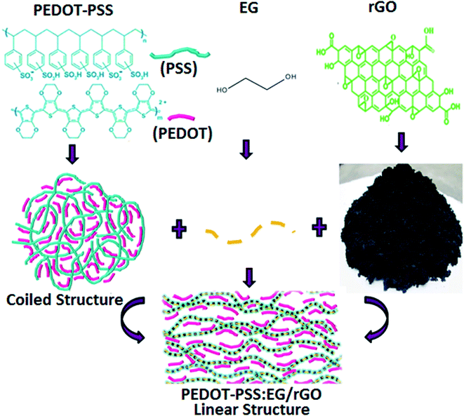
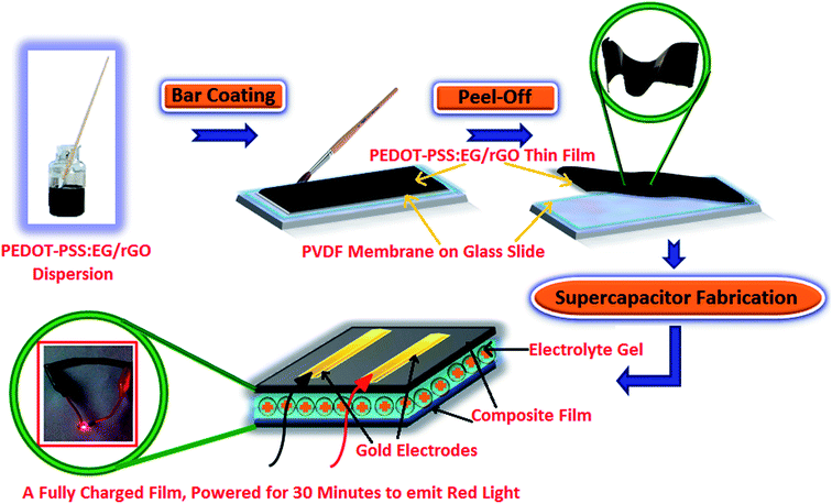
The original PEDOT–PSS suspension (as procured) was filtered using 0.2 μm syringe. Filtered PEDOT–PSS dispersion was sonicated prior to use, to which ethylene glycol (EG) was added at 10 vol%. The resulting solution of PEDOT–PSS:EG was further sonicated for 60 min for uniform dispersion of PEDOT–PSS and EG. The nanocomposite dispersions were prepared by adding rGO into PEDOT–PSS:EG suspension. Different nanocomposite samples were prepared with varying content of rGO (2 wt%, 4 wt%, 6 wt%, 8 wt%, 10 wt% and 12 wt%) in PEDOT–PSS:EG. The mixtures of PEDOT–PSS:EG containing different loadings of rGO were further stirred overnight and sonicated for 1 hour to obtain uniform dispersion prior to use. In all the nanocomposites the content of PEDOT–PSS and EG was maintained constant with the variation in rGO content. The addition of EG results into conformational changes of PEDOT–PSS from coiled to linear structure with wrapping of PEDOT–PSS over rGO nanoparticles (as illustrated in schematic representation of Fig. 1). The mixture of PEDOT–PSS:EG/rGO with varying content of GO was bar coated on a hydrophilic PVDF membrane (substrate) with glass slide (as a base support) to obtain a uniform film. The film was allowed to dry at room temperature for few hours, and then heated in air atmosphere at 50 °C in an oven overnight to remove the moisture content. The free standing flexible films were peeled off from PVDF membrane. Along with the nanocomposite films, flexible film of pristine PEDOT–PSS was prepared in a similar manner using bar coating method on a PVDF membrane substrate (as illustrated in schematic representation of Fig. 2).
 |
| | Fig. 1 Schematic representation of composite formation with secondary doping. | |
 |
| | Fig. 2 Schematic representation of flexible electrode fabrication. | |
2.3 Preparation of the all solid-state supercapacitor
The films were assembled into two flexible electrodes for all solid state symmetric supercapacitors as follows. The electrolyte was prepared using a mixture of PVA powder (2 g), H3PO4 (3 g) and deionized water (20 mL). The mixture was heated to 90 °C with constant stirring, to obtain a clear gel. The resulting gel electrolyte was coated onto PEDOT–PSS:EG/rGO flexible thin films and dried at room temperature. Finally, two such gel coated flexible PEDOT–PSS:EG/rGO electrodes were sandwiched together (face to face such that both films are separated by the electrolyte gel between them) to form an integrated supercapacitor device. Gold electrodes were electrodeposited on one side of the flexible film (electrode) that acts as a current collector (as illustrated in schematic representation of Fig. 2). Symmetric supercapacitors with sandwich electrodes using pristine PEDOT–PSS were prepared in a similar manner for comparative studies.
2.4 Physical characterizations of the flexible nanocomposite films
The prepared thin films of pristine PEDOT–PSS:EG and PEDOT–PSS:EG/rGO nanocomposites were physically characterized using various analytical techniques to understand the morphological and structural features. The surface morphology of pure PEDOT–PSS and PEDOT–PSS:EG with rGO organic thin films were recorded by using SEM (Zeiss Ultra-60-Poland) and AFM (Brucker Dimension Icon-Japan). The chemical structure and different functional groups present in the prepared thin films were studied using a FTIR spectrophotometer (PerkinElmer Frontier-USA). The core shell information and binding energies of different functional groups existing in the prepared thin films were studied using an XPS photo spectrometer (Thermo Fisher, E. Grinsted-Japan). The XPS analysis of the prepared thin films was recorded in a standard mode using a light source of X-ray with spot area of 1500 μm2. The surface area, pore volume and pore size of the synthesized samples were investigated using Brunauer–Emmett–Teller method (BET). The thermal stability of the prepared thin films was investigated using a thermal analyzer (NETSCH STA-409PC-Germany).
2.5 Electrical characterizations of the flexible nanocomposite films
The temperature dependent conductivity measurements of the prepared thin films (both PEDOT–PSS and PEDOT–PSS:EG/rGO) were carried out by four probe technique using Keithley 2410 source meter (London) in the temperature range of 20–250 °C. The frequency dependent dielectric measurements of the prepared films were carried out by two probe method using LCR impedance analyzer (Wayne Kerr-6500B London) in the frequency range 100 Hz to 2 MHz.
2.6 Electrochemical characterizations of the flexible nanocomposite films
The electrochemical characterizations of the integrated supercapacitor devices were investigated through cyclic-voltammetry (CV), galvanostatic charge/discharge (GCD) and electrochemical impedance spectroscopy (EIS) using BioLogic electrochemical work station (multi-channel potentiostat/galvanostat, VSP-300) at ambient temperature in the frequency range 1 Hz to 3 kHz at an AC amplitude of 10 mV open circuit potential (OCP). The gold electrode was used as counter electrode, silver electrode as quasi reference electrode and nanocomposite films (PEDOT–PSS and PEDOT–PSS:EG/rGO) as working electrode. The cyclic voltammetry for different scan rates were performed at the electrochemical voltage window in the range 0–1.2 V. The GCD tests were carried out in a potential range 0–1.2 V at a constant current density of 0.5 A g−1. The geometrical area of each sandwich film used for investigation of electrochemical parameters was about (2.5 × 7) cm2.
3. Results and discussions
3.1 Scanning electron and atomic force microscopy (SEM/AFM)
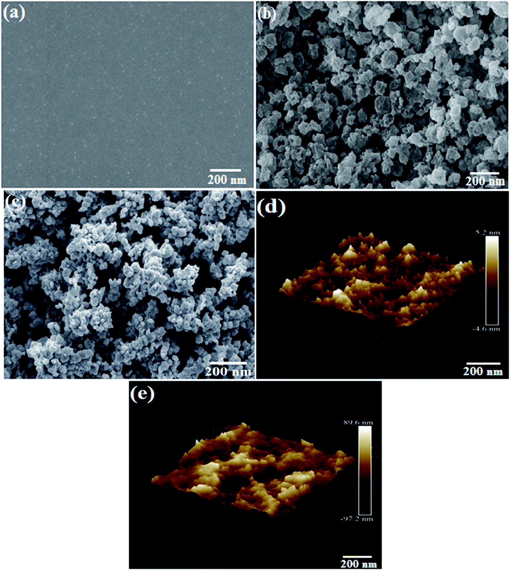
The SEM micrographs of pristine PEDOT–PSS, rGO and PEDOT–PSS:EG/rGO are shown in Fig. 3(a–c). Fig. 3(a) shows the SEM micrographs of secondary doped PEDOT–PSS (PEDOT–PSS:EG). The micrograph shows that, the addition of EG into PEDOT–PSS results into a well dispersed smooth surface showing the micro-grains in the polymer matrix. The micro-grains were formed in the polymer due to secondary doping of EG after post-curing the films. Fig. 3(b) shows the SEM micrograph of rGO, which reveal homogeneous distribution of synthesized rGO with particles of equal dimensions (average particle size). SEM micrograph of rGO loaded PEDOT–PSS:EG (Fig. 3(c)) shows formation of macro-pores with uniform distribution of rGO in polymer matrix. SEM micrograph of the nanocomposite also reveals that, the rGO nanoparticles were completely enveloped by PEDOT–PSS:EG. The presence of EG effectively prevents the re-stacking of rGO thereby providing the higher accessible surface area for electrochemical reactions. The formation of inter-connected network and macro-pores plays an important role in the enhanced conductivity and electrochemical performance of the nanocomposite films. The AFM topographic and 3D images of pure PEDOT–PSS and PEDOT–PSS:EG/rGO composite film optimized for 10wt% are shown in Fig. 3(d) and (e) respectively. The AFM image of pure PEDOT–PSS reveal the formation of a smooth film having a root mean square (RMS) roughness of 5.2 nm, inclusion of rGO, the corresponding RMS value of the composite film was observed to be 89.6 nm. The noticeable increase in the roughness of 10 wt% PEDOT–PSS:EG/rGO film compared to pure PEDOT–PSS film is attributed to the presence of rGO filler particles that may protrude from the surface thereby increasing the film roughness. The increase in surface roughness can be attributed due to increased pore size and pore volume due to the addition of rGO in PEDOT–PSS (which is evident from the BET data reported in Table 1). Further, the bright regions in the AFM image of pure PEDOT–PSS thin film are assigned to highly conductive PEDOT content and the dark regions correspond to insulating PSS-rich domains.35
 |
| | Fig. 3 SEM micrographs (a) PEDOT–PSS (b) rGO (c) EG:PEDOT–PSS with 10 wt% of rGO composites, (d) 3D AFM image of PEDOT–PSS (e) 3D AFM image of EG:PEDOT–PSS with 10 wt% of rGO composites. | |
Table 1 Surface area, average pore diameter and pore volume for different electrode materials
| Sl. no |
Electrode material |
Surface area (m2 g−1) |
Average pore diameter (nm) |
Pore volume (cm3 g−1) |
| 1 |
PEDOT–PSS |
90.123 |
4.56 |
0.21 |
| 2 |
PEDOT–PSS:EG |
122.534 |
7.42 |
0.286 |
| 3 |
PEDOT–PSS doped 2 wt% rGO |
220.343 |
9.45 |
0.33 |
| 4 |
PEDOT–PSS doped 4 wt% rGO |
235.565 |
11.45 |
0.42 |
| 5 |
PEDOT–PSS doped 6 wt% rGO |
240.343 |
15.87 |
0.54 |
| 6 |
PEDOT–PSS doped 8 wt% rGO |
250.343 |
19.34 |
0.75 |
| 7 |
PEDOT–PSS doped 10 wt% rGO |
265.434 |
29.45 |
0.84 |
| 8 |
PEDOT–PSS doped 12 wt% rGO |
272.14 |
52.364 |
0.97 |
3.2 Fourier transform-infra red spectroscopy (FTIR)
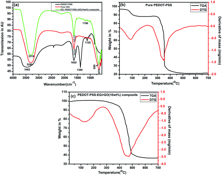
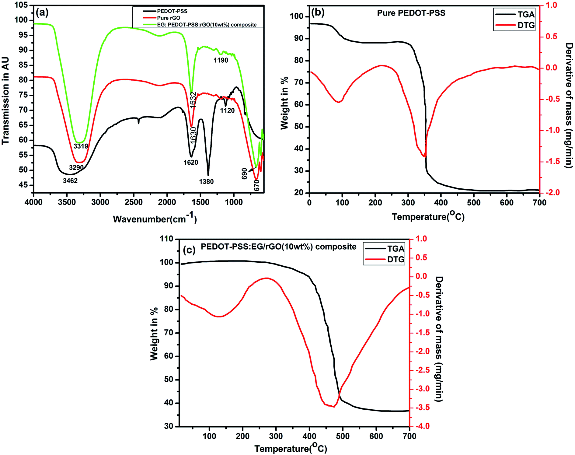
Chemical structure and the presence of functional groups of PEDOT–PSS, rGO and PEDOT–PSS:EG/rGO nanocomposite film analyzed by FTIR spectroscopy are shown in Fig. 4(a). The spectrum of PEDOT–PSS displays the presence of bands associated with the O–H group at 3462 cm−1, the vibrations at 1620 and 1380 are attributed to the C![[double bond, length as m-dash]](https://www.rsc.org/images/entities/char_e001.gif) C and C–C bonds of the thiophene ring56 and the band at 1120 cm−1 is assigned to the SO3H group of PSS.57 The spectra of rGO exhibits a strong broad band at 3290 cm−1 which is caused due to the O–H stretching modes of the hydroxyl groups, the band at 1630 cm−1 is associated with CO in carboxylic acid and carbonyl groups, the band at 670 cm−1 has been interpreted as originating due to aromatic C–H deformation.58 The FTIR spectra of the PEDOT–PSS:EG/rGO composite film retains the major characteristic peaks of both PEDOT:PSS and rGO. Some of the characteristic peaks of PEDOT–PSS and rGO either disappear or undergo slight redshift in the composite spectra due to the delocalization of electrons from aromatic ring, suggests a strong presence of π–π interaction between rGO and PEDOT–PSS. Also, it is worthwhile to note that the CC stretching of quinoid structure is shifted from 1620 to 1632 cm−1 in the composite spectra. Inclusion of EG in PEDOT–PSS transforms the benzoid structure into quinoid structure which indicates a conformation change from coil to linear structure as shown in schematic representation of Fig. 1. This leads to effective delocalization of π-electrons resulting in highly conductive PEDOT–PSS:EG/rGO film with a better charge carrier mobility.
C and C–C bonds of the thiophene ring56 and the band at 1120 cm−1 is assigned to the SO3H group of PSS.57 The spectra of rGO exhibits a strong broad band at 3290 cm−1 which is caused due to the O–H stretching modes of the hydroxyl groups, the band at 1630 cm−1 is associated with CO in carboxylic acid and carbonyl groups, the band at 670 cm−1 has been interpreted as originating due to aromatic C–H deformation.58 The FTIR spectra of the PEDOT–PSS:EG/rGO composite film retains the major characteristic peaks of both PEDOT:PSS and rGO. Some of the characteristic peaks of PEDOT–PSS and rGO either disappear or undergo slight redshift in the composite spectra due to the delocalization of electrons from aromatic ring, suggests a strong presence of π–π interaction between rGO and PEDOT–PSS. Also, it is worthwhile to note that the CC stretching of quinoid structure is shifted from 1620 to 1632 cm−1 in the composite spectra. Inclusion of EG in PEDOT–PSS transforms the benzoid structure into quinoid structure which indicates a conformation change from coil to linear structure as shown in schematic representation of Fig. 1. This leads to effective delocalization of π-electrons resulting in highly conductive PEDOT–PSS:EG/rGO film with a better charge carrier mobility.
 |
| | Fig. 4 (a) FTIR spectra of pure PEDOT–PSS, pure rGO and EG:PEDOT–PSS with 10 wt% of rGO composites, TGA/DTA spectra of (b) pure PEDOT–PSS and (c) EG:PEDOT–PSS with 10 wt% of rGO composites. | |
3.3 Theromogravimetric analysis (TGA)
The thermal stabilities of PEDOT–PSS and PEDOT–PSS:EG/rGO nanocomposites studied using TGA and DTA thermograms shown in Fig. 4(b) and (c). The thermograms of all the samples exhibit weight loss in three zones, viz. slight decomposition zone, fast decomposition zone and residual decomposition zone. The initial decomposition up to 100 °C is attributed to moisture evaporation from the films.59 The fast decomposition zone in PEDOT–PSS starts around 350 °C due to the oxidizing decomposition of the skeletal PEDOT and/or PSS backbone chain structures.60 Similarly, PEDOT–PSS:EG/rGO composite film exhibits a gradual weight loss between 400 °C to 500 °C due to thermal decomposition of PEDOT–PSS present on rGO surface. Further, in the residual decomposition zone which is beyond 500 °C, the overall weight loss of the composite film was found to be nearly 60%, suggests that PEDOT–PSS:EG/rGO composite film shows greater thermal stability compared to the pristine samples.
3.4 X-ray photo-spectroscopy (XPS)
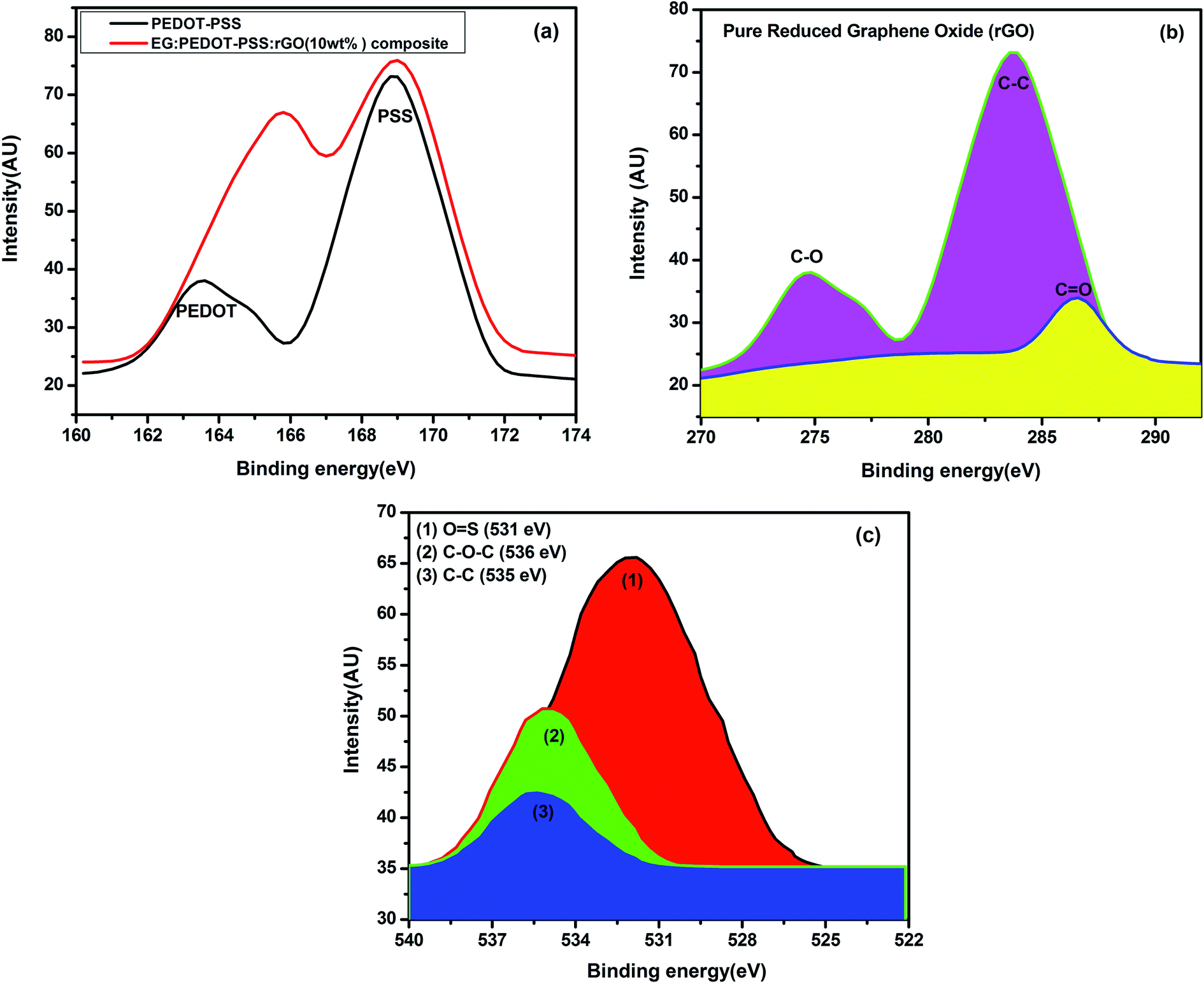
Fig. 5(a) shows the XPS spectra of PEDOT–PSS and PEDOT–PSS:EG/rGO (10 wt%) composite film. The higher and lower binding energy peaks in the S 2p spectra at 169 eV and 163 eV correspond to sulfur signals from the oxidized form of sulfonate in PSS chains and the thiophene in PEDOT chains respectively.61 Fig. 5(b) shows corresponding high resolution core level spectra for rGO sample in the carbon region. The XPS spectra of rGO indicates the presence of C–O (274.5 eV), C–C (283.6 eV) and CO (287 eV). The sulphur signals arising from different chemical environments of PEDOT and PSS results in significant differences in the values of binding energies (more than 5 eV). The addition of rGO has strengthened the sulphur signals of both PEDOT and PSS chains which indicates that the PEDOT and PSS chains are well separated due to their strong interaction with rGO. Fig. 5(b) shows the C 1s core level spectrum of PEDOT–PSS:EG/rGO film for the optimal content of rGO (10 wt%) in PEDOT–PSS. For the composite film, the spectrum has split into three peaks of OS, C–O–C and C–C species with binding energies of 531 eV, 536 eV and 535 eV respectively. Shifting in the bond after the addition of rGO indicates a strong π–π interaction between PEDOT chains and rGO, as well as a good compatibility between the hydrophilic group of rGO and PSS chains. The increase in the peak intensities of the binding energy curves of composite confirms the existence of rGO and the formation of PEDOT–PSS:EG/rGO composite film. Thus, XPS results along with SEM and FTIR spectroscopy confirms the wrapping of PEDOT:PSS over rGO nanoparticles assisted through EG.
 |
| | Fig. 5 (a) XPS spectra of pure PEDOT–PSS and EG:PEDOT–PSS doped 10 wt% of rGO composites, (b) XPS core level spectra of pure rGO in carbon region (c) XPS spectra of C 1s core of EG:PEDOT-PSS doped 10 wt% of rGO composites. | |
3.5 Electrical properties
A four probe method was used to investigate the sheet resistance (Rs) and the temperature dependent electrical conductivity (σdc) of the pristine PEDOT–PSS and PEDOT–PSS:EG/rGO nanocomposites using the relation
where “d” is the thickness of the film measured from atomic force microscope.
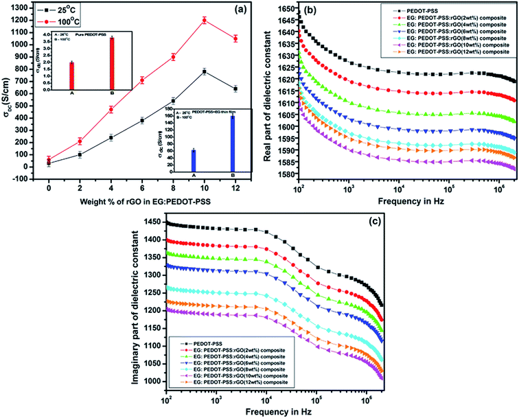
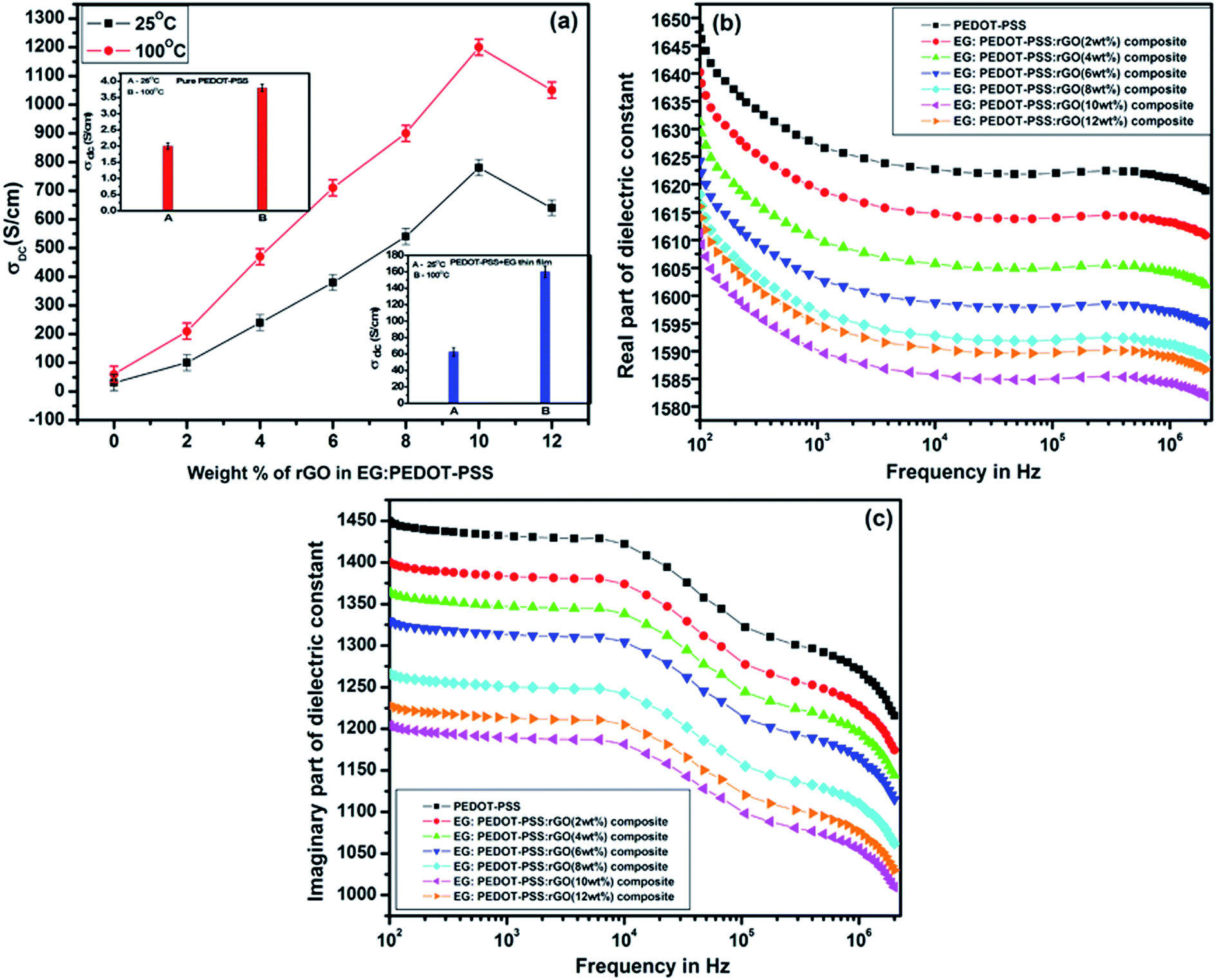
In our previous works, we have demonstrated that, the post treatment of PEDOT–PSS films using polar organic solvents with high boiling points can significantly enhance the conductivity of PEDOT–PSS aqueous dispersions by 2–3 orders of magnitude.34–37 In this study ethylene glycol (EG) is used as a solvent for the post treatment to enhance the conductivity of pristine PEDOT–PSS and PEDOT–PSS/rGO nanocomposites. Post treatment of EG into PEDOT–PSS/rGO leads to phase segregation of PEDOT and PSS, reduces the coulombic interactions between PEDOT and PSS phases. The presence of EG in PEDOT–PSS matrix also results into the conformational changes of polymer backbone chain from coiled (benzoid) to linear structures (quinoid) [as shown in Fig. 1] which plays a prominent role in the conductivity enhancement. The variation of temperature dependent conductivity for PEDOT–PSS and PEDOT–PSS:EG/rGO nanocomposites in shown in Fig. 6(a). The room temperature conductivity of PEDOT–PSS enhance from 2.5 S cm−1 to 765 S cm−1 for EG treated PEDOT–PSS with 10 wt% of rGO. Similarly the conductivity of PEDOT–PSS enhanced from 3.75 S cm−1(at 100 °C) to 1225 S cm−1 for EG treated PEDOT–PSS with 10 wt% of rGO. The presence of rGO and EG modifies the conductivity of PEDOT–PSS by several orders of magnitude, to the best of our knowledge the conductivity reported in this work is highest for PEDOT–PSS/rGO nanocomposites treated with polar solvents like EG. The conductivity of the nanocomposites shows a strong dependence on the content of rGO in the PEDOT–PSS, the presence of rGO is expected to enhance the surface roughness (as seen from the AFM images) due to improved phase segregation. The presence of rGO (up to 10 wt%) in PEDOT–PSS improves the π–π conjugation in the polymer backbone thereby creating a large number of de-localized charge carriers that can hop between favorable sites. The combined effect of EG and rGO in PEDOT–PSS improves the electrical conductivity of the nanocomposites containing various rGO loadings. For the rGO loadings >10 wt%, the composite shows decrease in conductivity due to re-stacking of rGO in PEDOT–PSS which partially blocks the charge carrier mobility as well as increased pore diameter of the composite (as seen in Table 1). Hence, these composites exhibit percolative conduction with threshold at 10 wt%.
 |
| | Fig. 6 DC conductivity plots of (a) EG:PEDOT–PSS:rGO for various content of rGO in PEDOT–PSS (inset: DC conductivities of pure PEDOT–PSS and PEDOT–PSS:EG), real and imaginary parts (b and c) of dielectric constant for pure PEDOT–PSS and doped PEDOT–PSS thin films. | |
The variations of real and imaginary parts of dielectric constant with frequency as shown in Fig. 6(b) and (c) have similar effects of EG and rGO in PEDOT–PSS matrix as observed in case of σdc. The thin films exhibit high dielectric constant at lower frequency regime which gradually decreases at higher frequencies due to dipole polarization effects. Both components of dielectric constants show a broad dispersion due to MWS interfacial polarizations. The decrease in the values of dielectric constant with different loadings of rGO is mainly due to resonant electronic transitions and increased interfacial polarizations at the grain boundaries. The nanocomposite films exhibit similar percolative behavior as observed in case of conductivity with a percolation threshold at 10 wt% of rGO in PEDOT–PSS.
3.6 Electrochemical properties
The electrochemical performance of the PEDOT–PSS and PEDOT–PSS:EG/rGO nanocomposites were investigated in flexible all solid state supercapacitors with symmetrical sandwich structures as represented in Fig. 2. The cyclic voltammetry curves (100 mV s−1) of PEDOT–PSS and PEDOT–PSS:EG with various loadings of rGO is shown in Fig. 7(a) show a quasi-rectangular behavior indicating excellent electrochemical double-layer capacitance characteristic.62 Among all the samples, PEDOT–PSS:EG/rGO (10 wt% composite) exhibit largest quasi-rectangular area. The improved electrochemical performance of PEDOT–PSS:EG/rGO (10 wt% composite) is mainly due to excellent particle dispersion and improved conductive networks formed between rGO nanoparticles and PEDOT–PSS polymer backbone chain. The enhanced conductivity due to addition of rGO in PEDOT–PSS:EG directly contributes for the improved electrochemical performances of the composite films. All the electrochemical performances of the nanocomposite films exhibit percolative behavior with a threshold at 10 wt% of rGO in PEDOT–PSS. The composite property deteriorates beyond 10 wt% mainly due to the restacking of rGO layers at higher concentrations. Fig. 7(b) shows the CV curves of PEDOT–PSS:EG/rGO (10 wt% composite) shows nearly rectangular shapes for increasing scanning rates (5 mV s−1 to 250 mV s−1) indicates an ideal capacitive behavior of the nanocomposite film due to reversible surface redox reactions of PEDOT–PSS and surface electro-adsorption of rGO. The behavior of CV curves indicated in Fig. 7(a and b) shows faster charge transfer rate and higher capacitance for nanocomposites than pristine PEDOT–PSS. The flexibility tests, of the planar of the PEDOT–PSS:EG/rGO 10 wt% nanocomposites were performed at different bending angles as shown in Fig. 7(c). The C–V curves of the nanocomposite film at scan rate of 250 mV s−1 were almost overlapped for increasing bending angles from 0° to 180°. These bending C–V performance confirm the excellent flexibility of these nanocomposites.
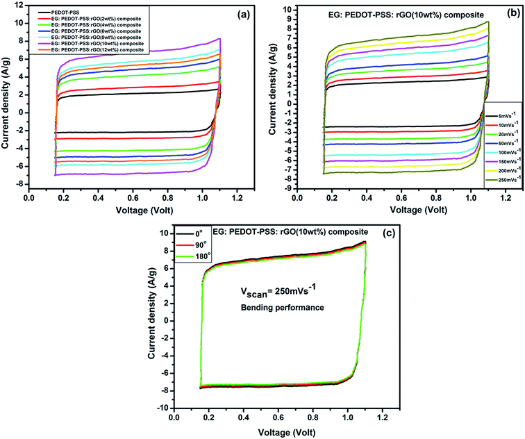 |
| | Fig. 7 (a) Cyclic voltagrams for pure PEDOT–PSS and doped PEDOT–PSS thin films (at the scanning rate of 100 mV s−1), (b) CV curves for EG:PEDOT–PSS with 10 wt% of rGO composites at different scanning rates, (in acetonitrile solution containing 1 M LiClO4 in the voltage range 0 to 1.2 V), (c) bending C–V performance of EG:PEDOT–PSS with 10 wt% of rGO composites at different angles. | |
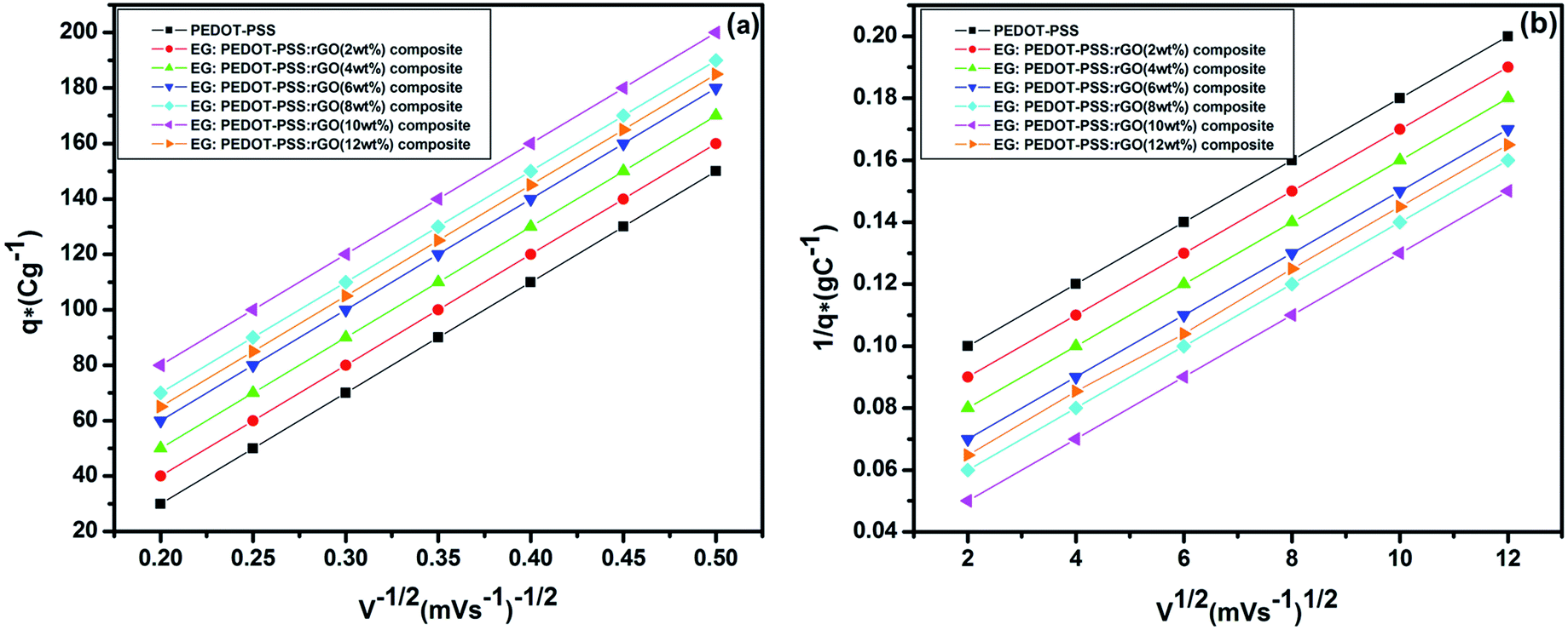
The voltammetric charge distribution (q*) is one of the important parameters to evaluate the active surface area of the electrode to understand its electrochemical performances of the supercapacitors.63 The voltammetric charge  is the sum of
  (outer region of the electrode in contact with electrolyte) and
  (inner electrode surface). The volumetric charges (q*) can be obtained by integrating the CV curves at different scan rates followed by the division with geometrical surface area of the electrode. From the Fig. 8(a) and (b) it is seen that the both q* and 1/q* linear dependency with V−1/2 and V1/2 respectively with different loadings of rGO in PEDOT–PSS. The extrapolation of q* with V−1/2 = 0, (Fig. 8(a)) signifies
  corresponds to easily accessible outer charges whereas extrapolation of 1/q* (Fig. 8(b)) provides
  . The linear dependence of both q* and 1/q* strongly suggests the increase in charge accumulation of the samples. The charge accumulation in the samples shows a strong dependence on rGO content in the PEDOT–PSS. The increased charge accumulation in the nanocomposites arises mainly due to the increased surface area and pore size distribution due to the loadings of rGO in PEDOT–PSS polymer chain as evident from SEM and AFM images. To analyze the effect of rGO loadings on surface area and pore geometry, we have carried out BET analysis of the pristine PEDOT–PSS and PEDOT–PSS:EG/rGO nanocomposites and the data is tabulated in Table 1. From the BET analysis it has been confirmed that the addition of rGO in PEDOT–PSS polymer chain substantially increases the active surface area, pore size and pore volume of the nanocomposites that plays a significant role in enhanced electrochemical performance.
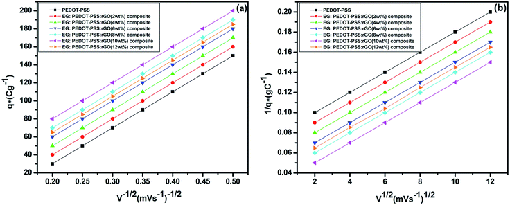 |
| | Fig. 8 Dependence of (a) voltammetric charge (q*) with inverse square root of scan rate (V−1/2) and (b) dependence of inverse voltammetric charge (1/q*) with square root scan rate (V1/2). | |
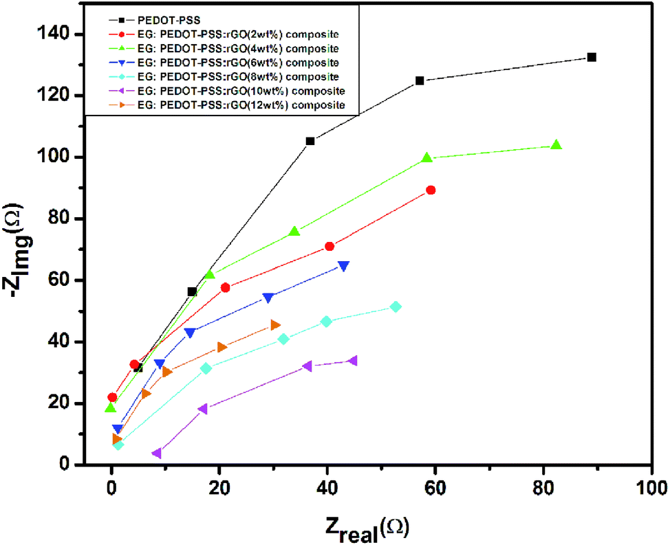
The capacitive behavior of pristine PEDOT–PSS and PEDOT–PSS:EG/rGO nanocomposites were studied through electrochemical impedance spectroscopy (EIS) by measuring the charge-transfer resistance (Rct) and equivalent-series resistance (Req). The Nyquist plots of different PEDOT–PSS:EG/rGO composites (Fig. 9) shows almost vertical plot at low frequency region where the electrodes are dominated by purely capacitive behavior.38,64,65 The EIS behavior of the nanocomposites in the Nyquist plots over the entire frequency range also shows desirable characteristic of this material as a high performance electrode due to smaller Rct of the PEDOT–PSS:EG/rGO nanocomposites. The Nyquist plot also suggests that the geometrical resistance of the nanocomposite decreases whereas the capacitance increases with increased rGO content. The addition of rGO is expected to improve the surface area and pore size distribution that leads to decrease in the internal resistance of the nanocomposites. The Nyquist plots of nanocomposites with improved conductivity and linear dependency at low frequency region, thus confirms the ideal capacitive behavior of electrodes.38
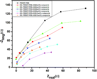 |
| | Fig. 9 Nyquist plots for pure PEDOT–PSS and EG doped PEDOT–PSS:rGO composites. | |
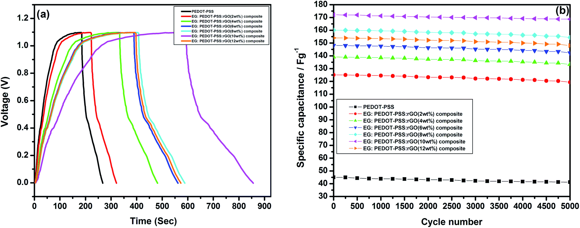
The galvanostatic charge–discharge (GCD) for PEDOT–PSS and PEDOT–PSS:EG/rGO nanocomposites is shown in Fig. 10(a). The GCD curve of pristine and rGO loaded PEDOT–PSS nanocomposite electrodes at a constant current density of 0.5 A g−1 shows nearly triangular shapes with potential of GCD curves varies linearly with time, suggests an excellent capacitive behavior of the nanocomposites. The non-linear slopes and semi triangular shapes of GCD curves corroborate the contribution of pseudo-capacitance arising from PEDOT–PSS. Moreover, it can be seen that, the PEDOT–PSS:EG/rGO (with 10 wt% of rGO) nanocomposite electrode endures longer charge–discharge time compared to other samples and neat PEDOT–PSS.
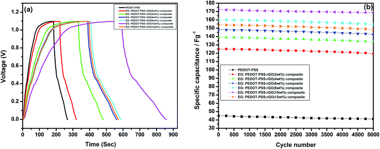 |
| | Fig. 10 (a) Galvanostatic charging–discharging curves for pure PEDOT–PSS and EG doped PEDOT–PSS:rGO composites, (b) variation of specific capacitance for pure PEDOT–PSS and EG doped PEDOT–PSS:rGO composites. | |
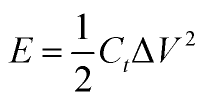
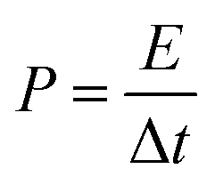
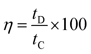
The specific capacitance Csc (F g−1), energy density E (W h kg−1), power density P (W kg−1), the coulombic efficiency η of all the samples were obtained from the GCD plots using the following equations
| |
 | (1) |
Ct (specific capacitance of the super capacitor),
I being the discharge current, Δ
t is the charging time,
S the effective surface area and Δ
V is the voltage distribution window.
Csc (specific capacitance of the electrode)
| |
 | (3) |
E, is energy density
| |
 | (4) |
P, is the power density
| |
 | (5) |
η is the coulombic efficiency.
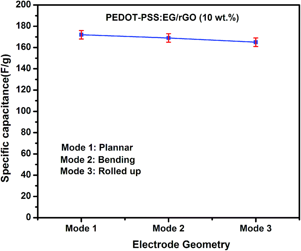
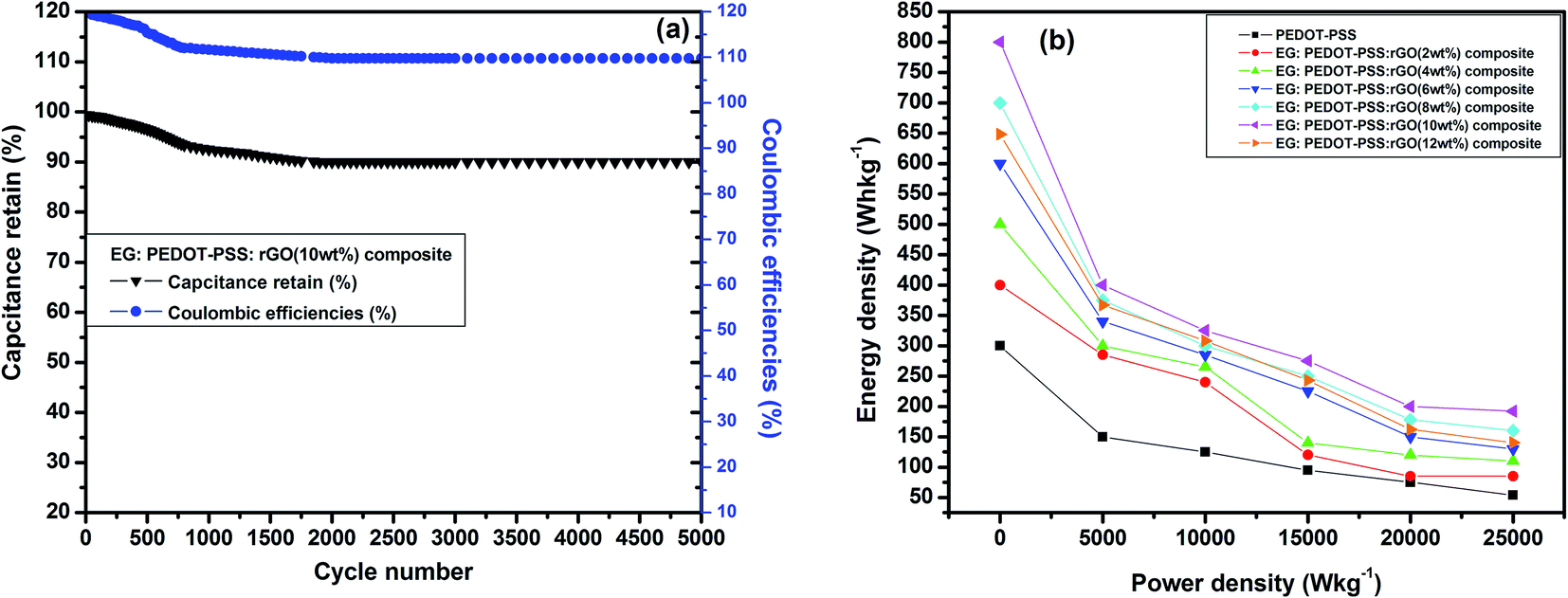
Fig. 10(b) shows the variation of specific capacitance Csc for pristine PEDOT–PSS and PEDOT–PSS:EG/rGO nanocomposites at a current density of 0.5 A g−1, the specific capacitance (Csc) of the nanocomposites shows a remarkable improvement in comparison to pristine PEDOT–PSS. The Csc values for PEDOT–PSS:EG/rGO (with 10 wt%) electrode is as high as ∼174 (F g−1), which is nearly 4 times more than that of pristine PEDOT–PSS (∼40 F g−1). The increase in Csc values of the nanocomposites is attributed to the larger inter-layer spacing of the composites due to the presence of rGO. Formation of inter-layer spacing helps the larger ions in the solid state electrolyte to penetrate deep into the inter-layer spacing and access the interior of the surface. Due to increased charge accumulation (which increase with rGO content as evident from Fig. 7(c)) in the nanocomposites assisted by increased surface area provides better Csc values for these nanocomposites when compared to neat PEDOT–PSS. To further analyze the electrochemical performance of these nanocomposites, the specific capacitance were measured in various modes such as planar, bending and rolled-up states as shown in Fig. 11. It is interesting to see that, the nanocomposites retains almost similar values of specific capacitance (Csc) at different geometries (planar, bending and rolled up) which suggests their utilization as flexible electrodes in supercapacitor fabrication. Fig. 12(a) shows the variation of capacitance retention (%) and coulombic efficiencies (%) of the PEDOT–PSS:EG/rGO (with 10 wt%) nanocomposite. Both capacitance retention and coulombic efficiencies show constant values up-to 5000 cycles of charging-discharging process without much deviation. The nanocomposite electrode exhibit capacitance retention of ∼90% over 5000 cycles of operation that shows long time stability, which is an ideal characteristic of high performance supercapacitor electrode. The coulombic efficiency of the nanocomposites also shows stable values over 5000 cycles of operation indicate minimum energy dissipation during the cycle of charge–discharge process. There is also remarkable improvement in the values of energy density and power density of nanocomposites as indicated in the Ragone plot of Fig. 12(b). The maximum energy density for neat PEDOT–PSS was found to be 300 W h kg−1 at a power density 500 W kg−1, whereas the device containing optimal content of rGO (10 wt%) in PEDOT–PSS:EG shows a remarkable increase in the energy density ∼810 W h kg−1 at the power density of 500 W kg−1. The nanocomposite (with 10 wt% of rGO) still exhibit a very high energy density values ∼ 210 W h kg−1 for the power densities as high as ∼25000 W kg−1, which demonstrates excellent capacitive performance of the nanocomposite film. The specific capacitance Csc, the capacitance retention, the coulombic efficiencies, the energy and power densities of the nanocomposites used in present investigation based on PEDOT–PSS:EG/rGO shows improved performance in comparison to recent available literature on supercapacitors based on PEDOT–PSS nanocomposites.9,10,38,64–66 Hence the secondary doping technique using EG adopted in this work plays a significant role in the supercapacitor performance with improved properties.
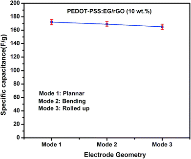 |
| | Fig. 11 Variation of specific capacitance as a function of electrode geometry. | |
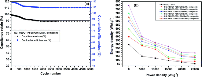 |
| | Fig. 12 (a) Capacitance retention (%) and coulombic efficiency (%) over 5000 cycles at constant current density (1 A g−1), (b) energy density versus power density (Ragone plot) for all the composite thin films. | |
4. Conclusions
In summary, we demonstrate a facile and efficient way to prepare secondary doped PEDOT–PSS/rGO nanocomposites using EG for flexible supercapacitor electrode applications. The structural and morphological features of the composites were analyzed by various analytical techniques. The conductivity of secondary doped PEDOT–PSS/rGO nanocomposites enhances by several orders of magnitude for the optimal content of rGO (10 wt%) in comparison to neat PEDOT–PSS. The PEDOT–PSS:EG/rGO nanocomposites with high flexibility and conductivity were used to assemble a symmetrical double layer all solid-state supercapacitor device. The CV and GCD curves of the nanocomposite electrodes show excellent capacitive behavior. Specific capacitance of PEDOT–PSS:EG/rGO nanocomposite electrodes delivers a capacitance of 174 F g−1. The presence of rGO and EG acts as an active material in an electrochemical reaction and the conductive network with increased pore density and surface area facilitates more ions to penetrate into the electrode material, thereby enhancing the specific capacitance. The bending C–V performance of these nanocomposites remains unaffected with increasing bending angles. Moreover, these flexible electrodes exhibit excellent cyclic stability (capacitance retention of ∼90% and coulombic efficiency of ∼110%) with continuous charging-discharging up-to 5000 cycles. Notably, the flexible films of PEDOT–PSS:EG/rGO nanocomposites performed better interms of their conductivity and electrochemical behavior in comparison to previous reports. Considering the need for commercially inexpensive, flexible, light-weight, environment friendly, rechargeable supercapacitors with excellent electrochemical properties, the composites investigated in the present study are promising candidates for high-performance flexible all solid-state supercapacitor devices for large scale practical applications.
Conflicts of interest
Authors listed in the manuscript certify that they have NO affiliations with or involvement in any organization or entity with any financial interest or non-financial interest in the subject matter or materials discussed in this manuscript.
Acknowledgements
Authors would like to acknowledge the financial support towards this research from Deanship of Scientific Research (DSR), University of Tabuk, Tabuk, Saudi Arabia, under research grant no. S-1439-0173.
References
- C.-T. Chien, P. Hiralal, D.-Y. Wang, I.-S. Huang, C.-C. Chen, C.-W. Chen, A. Gehan and J. Amaratunga, Small, 2015, 11, 2929 CrossRef CAS PubMed.
- P. Kumar Panda, A. Grigoriev, Y. K. Mishra and R. Ahuja, Nanoscale Adv., 2020, 2, 70–108 RSC.
- J. Yun, Y. Lim, G. N. Jang, D. Kim, S.-J. Lee, H. Park, S. Y. Hong, G. Lee and J. S. Ha, Nano Energy, 2016, 19, 401 CrossRef CAS.
- P. Simon, Y. Gogosti and B. Dunn, Science, 2014, 343, 1210 CrossRef CAS PubMed.
- Y. Shao, M. F. Kady, L. J. Wang, Q. Zhang, Y. Li, H. Wang, M. F. Mousavi and R. B. Kaner, Chem. Soc. Rev., 2015, 44, 3639 RSC.
- L. Nyholm, G. Nystrom, A. Mihranyan and M. Stromme, Adv. Mater., 2011, 23, 3751 CAS.
- O. Parlak, Y. K. Mishra, A. Grigoriev, M. Mecklenburg, W. Luo, K. Scott, A. Salleo, K. Schulte, R. Ahuja, R. Adelung, A. P. F. Turner and A. Tiwari, Nano Energy, 2017, 34, 570 CrossRef CAS.
- A. Muhulet, F. Miculescu, S. IoanVoicu, F. Schütt and Y. K. Mishra, Mater. Today Energy, 2018, 9, 154 CrossRef.
- Y. Liu, B. Weng, J. M. Razal, Q. Xu, C. Zhao, Y. Hou, S. Seyedin, R. Jalili, G. G. Wallace and J. Chen, Sci. Rep., 2015, 5, 17045 CrossRef CAS PubMed.
- B. Li, J. Cheng, Z. Wang, Y. Li, W. Ni and B. Wang, J. Power Sources, 2018, 376, 117 CrossRef CAS.
- M. Sawangphruk, P. Srimuk, P. Chiochan, A. Krittayavathananon, S. Luanwuthi and J. Limtrakul, Carbon, 2013, 60, 109 CrossRef CAS.
- X. Jiang, Y. Cao, P. Li, J. Wei, K. Wang, D. Wu and H. Zhu, Mater. Lett., 2015, 140, 43 CrossRef CAS.
- R. Jalili, J. M. Razal and G. G. Wallace, Sci. Rep., 2013, 3, 3438 CrossRef PubMed.
- X. Chen, H. Lin, P. Chen, G. Guan, J. Deng and H. Peng, Adv. Mater., 2014, 26, 4444 CrossRef CAS PubMed.
- X. Li, X. Li, J. Cheng, D. Yuan, W. Ni, Q. Guan, L. Gao and B. Wang, Nano Energy, 2016, 21, 228 CrossRef CAS.
- L. Shen, L. Du, S. Tan, Z. Zang, C. Zhao and W. Mai, Chem. Commun., 2016, 52, 6296 RSC.
- C. Yang, J. Shen, C. Wang, H. Fei, H. Bao and G. Wang, J. Mater. Chem. A, 2013, 2, 1458 RSC.
- Y. Zhao, J. Liu, Y. Hu, H. Cheng, C. Hu, C. Jiang, L. Jiang, A. Cao and L. Qu, Adv. Mater., 2013, 25, 591 CrossRef CAS PubMed.
- Q. Wu, Y. Xu, Z. Yao, A. Liu and G. Shi, ACS Nano, 2010, 4, 1963 CrossRef CAS PubMed.
- D. W. Wang, F. Li, J. Zhao, W. Ren, Z. G. Chen, J. Tan, Z. S. Wu, I. Gentle, G. Q. Lu and H. M. Cheng, ACS Nano, 2009, 3, 1745 CrossRef CAS PubMed.
- H. Zhang, Z. Hu, M. Li, L. Hu and S. Jiao, J. Mater. Chem. A, 2014, 2, 17024 RSC.
- J. Zhang and X. S. Zhao, J. Phys. Chem. C, 2012, 116, 5420 CrossRef CAS.
- A. Savva, E. Georgiou, G. Papazoglou, A. Z. Chrusou, K. Kapnisis and S. A. Choulis, Sol. Energy Mater. Sol. Cell., 2015, 132, 507 CrossRef CAS.
- T. R. Chou, S. H. Chen, Y. T. Chiang and C. Y. Chao, J. Mater. Chem. C, 2015, 3, 3760 RSC.
- X. Wu, J. Liu and G. He, Org. Electron., 2015, 22, 160 CrossRef CAS.
- W. Zhou and J. Xu, Electrochim. Acta, 2016, 222, 1895 CrossRef CAS.
- H. Zhou, G. Han, Y. Chang, D. Fu and Y. Xiao, J. Power Sources, 2015, 274, 229 CrossRef CAS.
- J. Saghaei, A. Fallahzadeh and T. Saghaei, Org. Electron., 2015, 24, 188 CrossRef CAS.
- J. Saghaei, A. Fallahzadeh and M. H. Yousefi, Org. Electron., 2015, 19, 70 CrossRef CAS.
- S. F. Tseng, W. T. Hsiao, K. C. Huang and D. Chiang, Appl. Phys. A, 2013, 112, 41 CrossRef CAS.
- Z. Li, G. Ma, R. Ge, F. Qin, X. Dong, W. Meng, T. Liu, J. Tong, F. Jiang, Y. Zhou, K. Li, X. Min, K. Huo and Y. Zhou, Angew. Chem., Int. Ed., 2016, 55, 979 CrossRef CAS PubMed.
- Y. Gao, Nanoscale Res. Lett., 2017, 12, 387 CrossRef PubMed.
- K. Sun, S. Zhang, P. Li, Y. Xia, X. Zhang, D. Du, F. H. Isikgor and J. Ouyang, J. Mater. Sci.: Mater. Electron., 2015, 26, 4438 CrossRef CAS.
- A. Pasha, A. S. Roy, M. V. Murugendrappa, O. A. Al-Hartomy and K. Syed, J. Mater. Sci.: Mater. Electron., 2016, 27, 8332 CrossRef CAS.
- A. Pasha, K. Syed, O. A. Al-Hartomy, M. Lakshmi and K. G. Manjunatha, RSC Adv., 2018, 8, 18074 RSC.
- K. Syed, A. Pasha, A. S. Roy, A. Parveen and N. Badi, J. Electron. Mater., 2017, 46, 4439 CrossRef.
- A. Pasha, K. Syed, F. A. Khan and N. Dhananjaya, Iran. Polym. J., 2019, 28, 183 CrossRef CAS.
- X. Mao, W. Yang, X. He, Y. Chen, Y. Zhao, Y. Zhou, Y. Yang and J. Xu, Mater. Sci. Eng., B, 2017, 216, 16 CrossRef CAS.
- K. I. Bolotin, K. J. Sikes, Z. Jiang, M. Klima, G. Fudenberg, J. Hone, P. Kim and H. L. Stormer, Solid State Commun., 2008, 146, 351 CrossRef CAS.
- Z. Liu, Z. Li, Z. Xu, Z. Xia, X. Hu, L. Kou, L. Peng, Y. Wei and C. Gao, Chem. Mater., 2014, 26, 6786 CrossRef CAS.
- Y. Zhao, C. Jiang, C. Hu, Z. Dong, J. Xue, Y. Meng, N. Zheng, P. Chen and L. Qu, ACS Nano, 2013, 7, 2406 CrossRef CAS PubMed.
- C. Lee, X. Wei, J. W. Kysar and J. Hone, Science, 2008, 321, 385 CrossRef CAS PubMed.
- Z. Xu and C. Gao, Acc. Chem. Res., 2014, 47, 1267 CrossRef CAS PubMed.
- G. Qu, J. Cheng, X. Li, D. Yuan, P. Chen, X. Chen, B. Wang and H. Peng, Adv. Mater., 2016, 28, 3646 CrossRef CAS PubMed.
- Y. Sun, Q. Wu and G. Shi, Energy Environ. Sci., 2011, 4, 1113 RSC.
- Y. Shao, M. F. El-Kady, C. W. Lin, G. Zhu, K. L. Marsh, J. Y. Hwang, Q. Zhang, Y. Li, H. Wang and R. B. Kaner, Adv. Mater., 2016, 28, 6719 CrossRef CAS PubMed.
- J. Cheng, H. Xin, H. Zheng and B. Wang, J. Power Sources, 2013, 232, 152 CrossRef CAS.
- T. Huang, B. Zheng, Z. Liu, L. Kou and C. Gao, J. Mater. Chem. A, 2015, 3, 1890 RSC.
- C. Cui, W. Qian, Y. Yu, C. Kong, B. Yu, L. Xiang and F. Wei, J. Am. Chem. Soc., 2014, 136, 2256 CrossRef CAS PubMed.
- M. Oschatz, L. Borchardt, K. Pinkert, S. Thieme, M. R. Lohe, C. Ho-mann, M. Benusch, F. M. Wisser, C. Ziegler, L. Giebeler, M. Rummeli, J. Eckert and A. Eychmuller, Adv. Energy Mater., 2014, 4, 105 Search PubMed.
- Q. Wu, Y. Xu, Z. Yao, A. Liu and G. Shi, ACS Nano, 2010, 4, 1963 CrossRef CAS PubMed.
- G. Hatui, G. Chandra Naik, G. Udaybhanu, Y. K. Mishra and D. D. Pathak, New J. Chem., 2017, 41, 2716 RSC.
- Y. Sun and G. Shi, J. Polym. Sci., Part B: Polym. Phys., 2013, 51, 231 CrossRef CAS.
- J. Yan, Q. Wang, T. Wei and Z. Fan, Adv. Energy Mater., 2014, 4, 1300816 CrossRef.
- D. C. Marcano, et al., ACS Nano, 2010, 4(8), 4806 CrossRef CAS PubMed.
- H. Shi, C. C. Liu, J. K. Xu, H. J. Song, B. Y. Lu, F. X. Jiang, W. Q. Zhou, G. Zhang and Q. L. Jiang, ACS Appl. Mater. Interfaces, 2013, 5, 12811 CrossRef CAS PubMed.
- P. L. Anto, C. Y. Panicker, H. T. Varghese and D. Philip, J. Raman Spectrosc., 2006, 37, 1265 CrossRef CAS.
- Z. Wang, B. Huang, Y. Dai, Y. Liu, X. Zhang, X. Qin, J. Wang, Z. Zheng and H. Cheng, CrystEngComm, 2012, 14(5), 1687 RSC.
- S. J. Park, J. An, R. D. Piner, I. Jung, D. X. Yang, A. Velamakanni, S. T. Nguyen and R. S. Ruoff, Chem. Mater., 2008, 20, 6592 CrossRef CAS.
- Q. Jiang, C. Liu, H. Song, J. Xu, D. Mo, H. Shi, Z. Wang, F. Jiang, B. Lu and Z. Zhu, Int. J. Electrochem. Sci., 2014, 9, 7540 Search PubMed.
- D. Merche, J. Hubert, C. Poleunis, S. Yunus, P. Bertrand, P. De Keyzer and F. Reniers, Polym, 2010, 7, 836 CAS.
- T. Brousse, D. Belanger and J. W. Long, J. Electrochem. Soc., 2015, 162(5), 5185 CrossRef.
- P. Sen and A. De, Electrochim. Acta, 2010, 55, 4677 CrossRef CAS.
- Y. Chang, W. Zhou, J. Wu, Y. Guo, Q. Zhou, D. Li, D. Zhu, T. Li, G. Nie, Y. Du and J. Xu, Electrochim. Acta, 2018, 283, 744 CrossRef CAS.
- D. S. Patil, S. A. Pawar, J. Hwang, J. H. Kim, P. S. Patil and J. C. Shin, J. Ind. Eng. Chem., 2016, 42, 113 CrossRef CAS.
- X. Mao, X. He, J. Xu, W. Yang, H. Liu, Y. Yang and Y. Zhou, Nanoscale Res. Lett., 2019, 14, 267 CrossRef PubMed.
|
| This journal is © The Royal Society of Chemistry 2020 |
Click here to see how this site uses Cookies. View our privacy policy here. 
 Open Access Article
 This Open Access Article is licensed under a Creative Commons Attribution-Non Commercial 3.0 Unported Licence
 *abc,
Apsar Pashad,
Nacer Badiab,
Mohana Lakshmic and
Yogendra Kumar Mishra
*abc,
Apsar Pashad,
Nacer Badiab,
Mohana Lakshmic and
Yogendra Kumar Mishra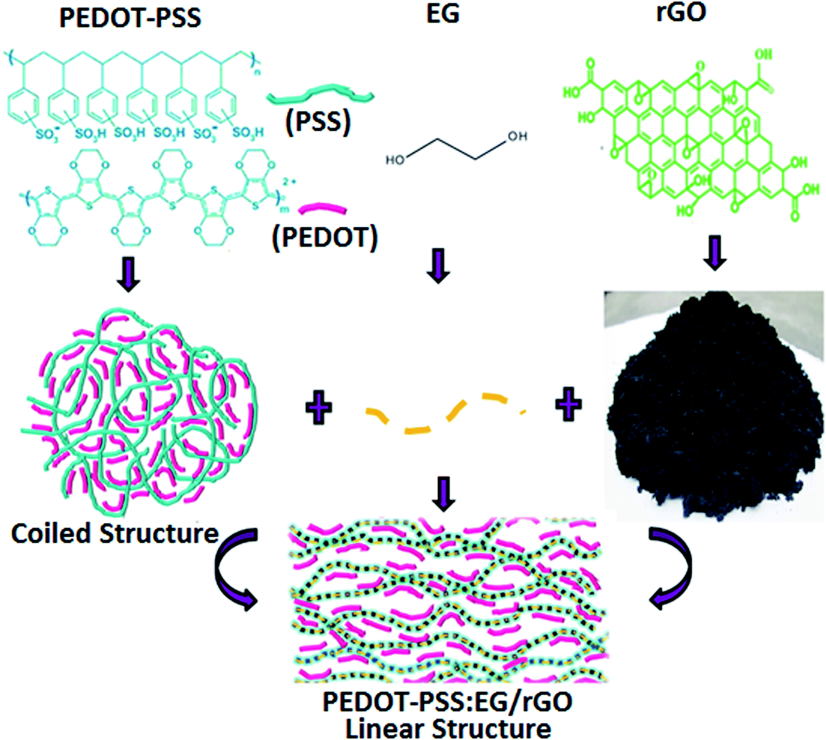


 is the sum of
  (outer region of the electrode in contact with electrolyte) and
  (inner electrode surface). The volumetric charges (q*) can be obtained by integrating the CV curves at different scan rates followed by the division with geometrical surface area of the electrode. From the Fig. 8(a) and (b) it is seen that the both q* and 1/q* linear dependency with V−1/2 and V1/2 respectively with different loadings of rGO in PEDOT–PSS. The extrapolation of q* with V−1/2 = 0, (Fig. 8(a)) signifies
  corresponds to easily accessible outer charges whereas extrapolation of 1/q* (Fig. 8(b)) provides
  . The linear dependence of both q* and 1/q* strongly suggests the increase in charge accumulation of the samples. The charge accumulation in the samples shows a strong dependence on rGO content in the PEDOT–PSS. The increased charge accumulation in the nanocomposites arises mainly due to the increased surface area and pore size distribution due to the loadings of rGO in PEDOT–PSS polymer chain as evident from SEM and AFM images. To analyze the effect of rGO loadings on surface area and pore geometry, we have carried out BET analysis of the pristine PEDOT–PSS and PEDOT–PSS:EG/rGO nanocomposites and the data is tabulated in Table 1. From the BET analysis it has been confirmed that the addition of rGO in PEDOT–PSS polymer chain substantially increases the active surface area, pore size and pore volume of the nanocomposites that plays a significant role in enhanced electrochemical performance.