
 Open Access Article
 This Open Access Article is licensed under a Creative Commons Attribution-Non Commercial 3.0 Unported Licence
The selective laser sintering of a polyamide 11/BaTiO3/graphene ternary piezoelectric nanocomposite†
Yipu Jin ,
Ning Chen,
Yijun Li and
Qi Wang*
,
Ning Chen,
Yijun Li and
Qi Wang*
State Key Laboratory of Polymer Materials Engineering, Polymer Research Institute of Sichuan University, Chengdu, 610065, China. E-mail: qiwang@scu.edu.cn; Fax: +86-28-85402465; Tel: +86-28-85405133
First published on 27th May 2020
Abstract
Piezoelectric materials featuring the capability of converting mechanical energy to electricity are very important for harvesting discrete mechanical energy to meet the rapidly increasing demand for cleaner energy. However, the intrinsic poor flexibility and processability make it difficult for current piezoelectric materials to fulfill their potential. This study reports a novel polyamide 11 (PA11)/BaTiO3 (BT)/graphene (Gr) ternary nanocomposite 3D printed part with significantly enhanced dielectric and piezoelectric properties due to its special discontinuous graphene network and microspores. The piezoelectric BT nanoparticles with excellent piezoelectric properties were uniformly dispersed into PA11 via a solid-state shear milling (S3M) technology. Moreover, via ultrasonic coating and selective laser sintering (SLS) technology, the discontinuous graphene network and microporous structures were both fabricated in the prepared 3D printed parts. The graphene interfaces acted as electrodes, and thus significantly increased the poling efficiency, while the porous structure further magnified the stress concentration. As a result, a piezoelectric coefficient (d33) of 3.8 pC N−1 and open-circuit voltage of 16.2 ± 0.4 V were obtained, exhibiting better comprehensive performances than those of most reported piezoelectric materials.
1. Introduction
As an important functional material, piezoelectric materials can convert mechanical energy to electricity or vice versa, and are widely used in electronics, sensors, ultrasound, and energy harvesting. Among them, piezoelectric generators have attracted the most attention in recent decades due to their capability to harvest discrete mechanical energy in the environment.1,2 However, due to the poor flexibility and processability of the traditional piezoelectric ceramic, the scalable fabrication and application of piezoelectric generators remain a big challenge.3,4Polymer/piezoelectric ceramic composites have the advantages of both piezoelectric ceramics and polymers, giving the material good flexibility, processing properties and piezoelectric properties.5,6 For the 0–3 piezoelectric composite, since most polymers have a lower dielectric constant compared with piezoelectric ceramic materials, most of the applied electric field will pass through the lower dielectric constant phase. In addition, the piezoelectric properties are limited by the effective poling of the ceramic particles.7,8 The addition of electric conductive fillers, such as metal particles, carbon nanotubes, or graphene, was an effective approach to improve the poling procedure and the resultant piezoelectric properties.9,10 Research has shown that the composite material exhibits maximum dielectric and piezoelectric properties near the insulator to the conductor percolation threshold value.11,12 However, the high concentration of the conductive filler raised the risk of an electric breakdown and resulted in low economic affordability. It was a competitive strategy to realize the selective distribution of fillers, and thus decrease the percolation threshold. The conductive filler was coated or restricted on the surface of the polymer particles, and then the selectively distributed structures were formed by hot pressing or other methods. By creating conductive interfaces between the polymer phase, the dielectric permittivity locally rose, which led to an enhancement of the dielectric properties.13,14 For instance, Zha et al.15 reported an isotactic polypropylene (iPP)/ethylene-α-octene block copolymer (OBC)/multi-walled carbon nanotube (MWCNT) ternary nanocomposite with ultrahigh dielectric permittivity by constructing a CNT network. Du et al.16 fabricated MWCNTs/high density polyethylene (HDPE) and graphene nanosheet (GNS)/HDPE composites with a conductive filler network. MWCNTs and GNSs were distributed along specific paths by solvent-assisted dispersion and hot-pressing methods, resulting in a low electrical percolation threshold of the composites. In addition, the structures of the network and the connection between nanoparticles were studied. However, the configurations of these materials were limited by low dimension (such as film or fiber-like geometry), and thus the voltage output and electromechanical response remained low.
Selective laser sintering (SLS), one of the important 3D printing technologies, can fabricate parts with complicated shapes, and is widely used in many fields.17,18 SLS processing is a shear-free and free-flowing process. The partially molten polymer powders can tightly adhere to each other without changing the selective distribution of fillers.19 Moreover, the sintering of the powder particles will create pores inside the parts, which can increase the pressure sensitivity and flexibility of the piezoelectric materials.20 Studies have shown that introducing porosity to piezoelectric parts could improve the energy conversion efficiency of the parts. Mao et al.21 demonstrated a nanogenerator design based on sponge-like mesoporous piezoelectric polyvinylidene fluoride (PVDF) thin films. Zhang et al.22 prepared a mesoporous piezoelectric β-phase PVDF film using dimethyl sulfoxide (DMSO). By controlling the porosity of the PVDF network, the PVDF–polydimethylsiloxane (PDMS) composite film showed an appreciable piezoelectric output. Therefore, the SLS technology not only provides a simple and effective method to manufacture piezoelectric polymer composites with 3D geometry, but also can optimize the output performance by designing unique structures.23,24
This paper reported a novel PA11/BaTiO3/graphene (PA11/BT/Gr) ternary nanocomposite part with discontinuous graphene network and micropores, which significantly enhanced the dielectric and piezoelectric properties. The PA11/BT/Gr piezoelectric composite materials combined the excellent piezoelectric properties of the piezoelectric ceramics (BT), the excellent SLS processing and mechanical properties of PA11, and the excellent electrical properties of Gr. Our invented solid-state shear milling (S3M) technology was used to realize the fine dispersion of BT particles in the PA11 matrix, and ultrasonic technology was used to prepare the graphene-coated PA11/BT composite powder. Selective laser sintering (SLS) technology was used to construct the unique discontinuous graphene network, as well as the microporous structures in the PA11/BT/Gr-coating parts. The structure and properties of the prepared PA11/BT/Gr ternary nanocomposite parts, as well as the affecting factors, were investigated.
2. Experimental
2.1. Materials
PA11 pellets were purchased from Rilsan Arkema, France.BaTiO3 (BT) particles with an average particle size of 500 nm were supplied by the Shandong Sinocera Functional Material Co., Ltd, China.
Graphene [98% pure GNP (SE1233), average diameter near 10 μm, and a specific surface area ranging from 400 to 550 m2 g−1] was supplied by The Sixth Element (Changzhou) Materials Technology Co., Ltd, China.
A flow additive of fumed silica, fine powder with a particle size of less than 10 nm, was purchased from the Shanghai Aladdin Bio-Chem Technology Co., Ltd, China.
2.2. Preparation of PA11/BT/graphene nanocomposite powders
The fabrication process is schematically shown in Fig. 1. The PA11 pellets and 60 wt% BT nanoparticles were fed into solid-state shear milling (S3M) equipment and ground for 10 cycles to prepare the PA11/BT compounding powders (Fig. 1(a)),25,26 which were extruded at 190–210 °C through a co-rotating twin-screw extruder to obtain pellets. Then, the PA11/BT nanocomposite powders (PA11/BT powders), which were suitable for SLS, were obtained by cryogenic grinding, drying, and sieving.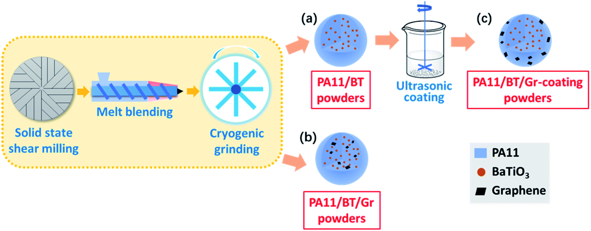 | ||
| Fig. 1 Schematic illustration of the procedures for preparing (a) PA11/BT powders, (b) PA11/BT/Gr powders, and (c) PA11/BT/Gr-coating powders. | ||
As shown in Fig. 1(c), graphene-coated PA11/BT composite powders (PA11/BT/Gr-coating powders) with 60 wt% BT and 0.35 wt% graphene nanoparticles were prepared by the solvent-assisted dispersion process under ultrasonication: graphene was dispersed in ethanol by ultrasonication for 2 h to get a homogeneous dispersion. A certain amount of the PA11/BT powder was added to the graphene suspension under ultrasonication and stirring for about 4 h. Then, the mixture suspension was filtered with a Buchner funnel under reduced pressure. The obtained graphene-coated PA11/BT composite powders were dried in a vacuum oven at 80 °C for 24 h.
For comparison, the PA11/BT/Gr powders (Fig. 1(b)) with the same amount of graphene was prepared only by solid-state shear milling, melt blending, and cryogenic grinding, which led to uniformly dispersed Gr in PA11.
In addition, all composite powders were sieved to remove particles of undesirable size and modified by fumed silica to improve their flowability.
2.3. Selective laser sintering process
The sintering experiments were carried out using the HT251P commercial SLS machine made by the Hunan Farsoon High-Tech Co., Ltd (China). The SLS machine was equipped with a continuous wave CO2 laser. The sintering parameters were as follows: laser power of 10 W; beam diameter of 200 μm; laser scan speed and spacing of 7.6 m s−1 and 100 μm; powder layer thickness of 0.1 mm. Three kinds of SLS parts and corresponding powders are shown in Table 1.| Sample | Processing methods | Features and structures |
|---|---|---|
| PA11/BT parts | S3M and SLS | Uniformly dispersed BT |
| PA11/BT/Gr parts | S3M and SLS | Uniformly dispersed BT and Gr |
| PA11/BT/Gr-coating parts | S3M, ultrasonic dispersing and SLS | Uniformly dispersed BT and discontinuous Gr network |
2.4. Characterization
An Inspect F field-emission electron microscope (FEI, Japan) for scanning electron microscopy (SEM) with an acceleration voltage of 20 kV was used to assess the morphology of the nanocomposite powder particles and composites. All samples were sputtered with gold under vacuum.XRD patterns were recorded on a Philips X'-Pert Pro Diffractometer. Ni-filtered Cu Kα radiation (λ = 0.1540 nm) was generated at 40 kV and 35 mA. The instrument was run at a scanning rate of 0.06° s−1 within an angle (2θ) ranging from 5° to 50°.
The size and size distribution of the powders and particle shape were analyzed using a particle size and image analyzer (Microtrac S3500, USA).
The flow and accumulation properties of the powders were studied on a Freeman FT4 Powder Rheometer (Freeman Technology, UK). The powder properties, including compressibility and shear property, were characterized by different test modes.
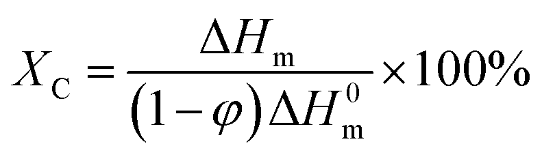
The thermal properties of the powders were studied on a differential scanning calorimetry (DSC, Q20, TA) system from 40 °C to 230 °C with a heating rate of 10 °C min−1 in a nitrogen atmosphere. The degree of crystallization was calculated by the following equation:
 | (1) |
The dielectric property measurement was carried out with an Agilent HP4294A system in the frequency range of 102 to 106 Hz. Disc-shaped SLS printed test specimens with a CAD model size of Φ24 mm × 1 mm were prepared. Since deviations occurred between the sintered part and CAD data, the actual measured size data was used in the measurement.
The piezoelectric performance was measured with a quasistatic d33 apparatus ZJ-3A (Institute of Acoustics, Chinese Academy, China) at a fixed frequency of 110 Hz. The poling of the electrode samples was performed by applying an electric field of 5 kV mm−1 at 80 °C in a silicone oil bath for 15 min to ensure uniform heating. The samples were placed in a Petri dish for 24 h before testing.
The open-circuit voltage and the short-circuit current of the parts were obtained by a self-designed device. The polarized parts were adhered to the front and back sides of the double-sided electric aluminum foil, and connected to the iron plate of the experimental device with the position facing the impact head. The linear motor was used to strike the parts according to a certain period, and the generated electric signal was amplified with the output sent to the computer.
3. Results and discussion
3.1. Powder characterization
The morphology of the PA11/BT powders, PA11/BT/Gr powders and PA11/BT/Gr-coating powders are shown in Fig. 2. All samples exhibited irregular, but relatively uniform shapes. The BT nanoparticles were uniformly dispersed and embedded into the PA11 matrix. In addition, the intimacy between the PA11 and BaTiO3 particles became better, indicating the improved interfacial compatibilities of these two components. The powerful three-dimensional shearing force of the solid-state shear milling (S3M) could simultaneously achieve the uniform dispersion of nanoparticles in the polymer matrix and the enhancement of their interface compatibilities.28 Therefore, the synergistic effect of S3M and melt blending could achieve good compounding of the polymer and nanoparticles. For PA11/BT/Gr powders (Fig. 2(b1)), it was difficult to find graphene on the powder surface due to the low content and uniform dispersion of graphene. As shown in the magnified SEM images of the PA11/BT/Gr-coating powders (Fig. 2(c1)), graphene was uniformly coated on the surface of the PA11/BT powders without obvious agglomerations. During the agitating process, the graphene was dispersed in ethanol solution under ultrasonication and gradually deposited onto the surface of PA11/BT powders. There was no obvious chemical interaction occurring between graphene and the PA11/BaTiO3 composite (Fig. S1†). The interaction between graphene and the composite powders was the van der Waals forces interfacial adhesion due to electrostatic interactions.29–31 The coating of graphene enabled the PA11/BT/Gr-coating powders with better sintering performance, and allowed the discontinuous graphene network to be constructed by SLS processing. The particle size of three kinds of powders was measured at about 50 μm with relatively narrow normal distribution, which was suitable for the SLS process.32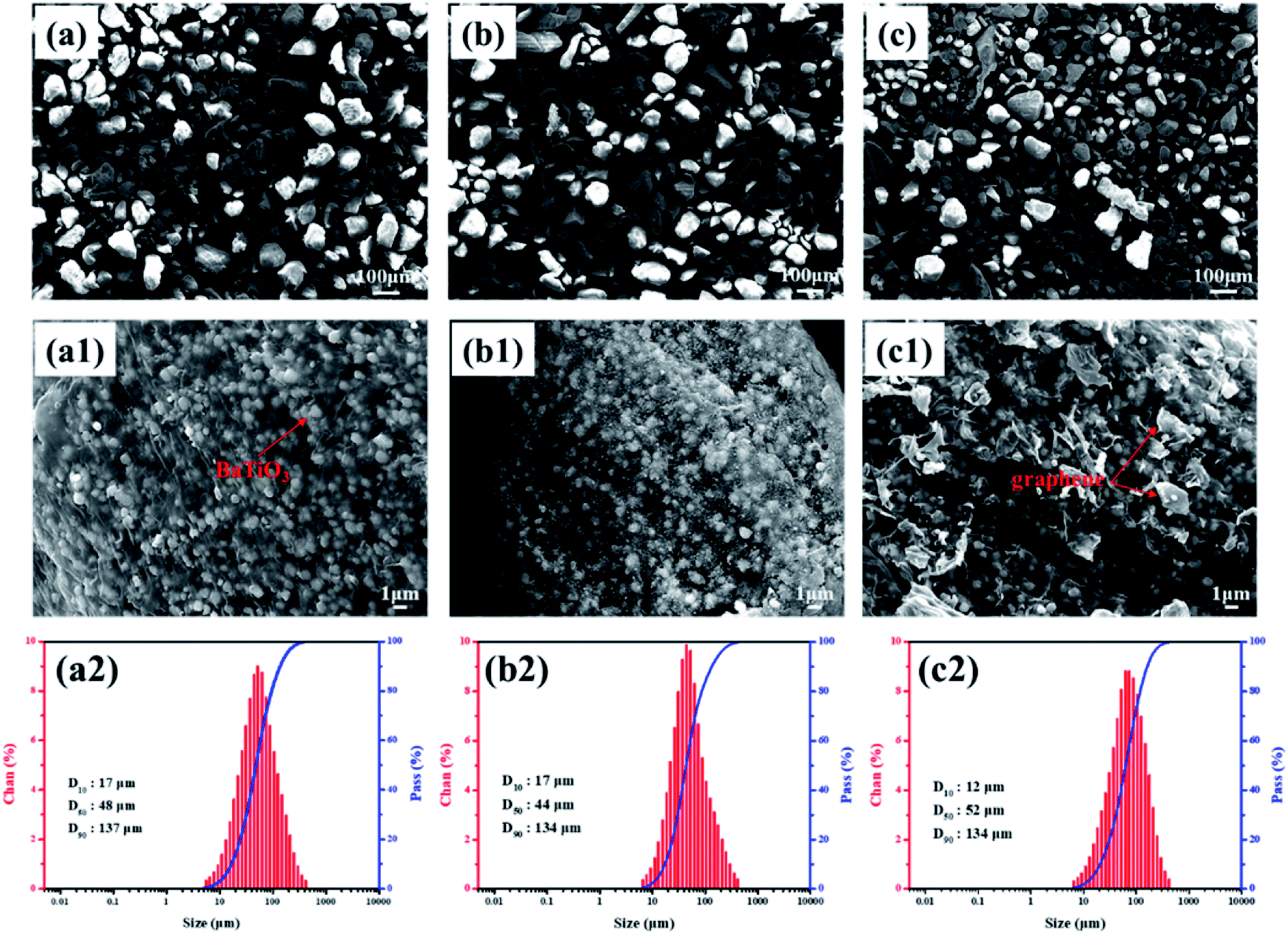 | ||
| Fig. 2 The SEM images and the size distribution of the (a) PA11/BT powders, (b) PA11/BT/Gr powders, and (c) PA11/BT/Gr-coating powders. | ||
The XRD patterns of the PA11/BT, PA11/BT/Gr, and PA11/BT/Gr-coating powders are presented in Fig. 3(a). Due to the high content of BT in the composites, the spectrum mainly showed the peak of BT, while the intensities of the peak related to PA11 almost disappeared. The XRD patterns showed six diffraction peaks, which could be attributed to the (100), (110), (111), (200), (210) and (211) reflections of the perovskite BaTiO3. The splitting peaks at 2θ = 45° were the (002) and (200) reflections of the tetragonal BT powder, indicating that the BT nanoparticles have an excellent ferroelectric tetragonal phase.33,34 In addition, there was no obvious difference in the diffraction peaks of the PA11/BT, PA11/BT/Gr, and PA11/BT/Gr-coating powders. Therefore, the BaTiO3 nanoparticles still showed ferroelectric properties after the S3M and ultrasonic coating process.
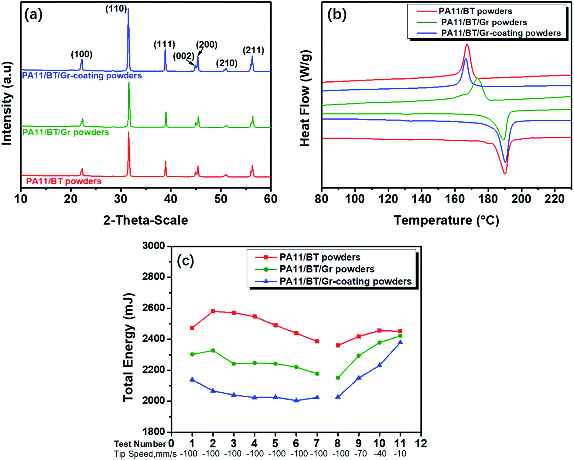 | ||
| Fig. 3 (a) X-ray diffraction patterns, (b) DSC heating and cooling curves, and (c) flow energy measurements at fixed and variable blade tip speeds of the PA11/BT powders, PA11/BT/Gr powders and PA11/BT/Gr-coating powders. | ||
Since the main stages of the SLS process need to heat the material above the melting temperature and then cool back to room temperature, the possible range of the SLS processing temperature can be reflected by the DSC measurement.35 Fig. 3(b) shows the heating and cooling curves of the PA11/BT, PA11/BT/Gr, and PA11/BT/Gr-coating powders, respectively. It was found in Table 2 that the coating of graphene made the PA11/BT/Gr-coating powders have a higher initial melting temperature than the other two powders. Since the preheating temperature of the powder bed is usually just below the Tim, the PA11/BT/Gr-coating powders should be preheated at a higher temperature of 181 °C in order to avoid the buckling deformation of the sintered part, while the powder bed preheating temperature of the PA11/BT powders and PA11/BT/Gr powders was determined to be 178 °C. The sintering window (SW) of the polymer is the region between the Tim and Tic, which is a very important process parameter for SLS of the polymers. If the Tim and Tic of the polymer are too close, the processed powder will crystallize quickly as it cools, increasing the probability of shrinkage. As listed in Table 2, the PA11/BT/Gr-coating powders exhibited a wider SW of 15.3 °C, while the SW of the PA11/BT/Gr powders sharply reduced to 2.5 °C due to the higher Tic. This was due to the nucleating effect of the well-dispersed graphene in the matrix, causing a higher crystallization temperature. Therefore, the coating of graphene provided a wider sintering window for the PA11/BT/Gr-coating powders.
| Samples | Tim (°C) | Tpm (°C) | Tic (°C) | Tpc (°C) | ΔHm (J g−1) | Xc (%) | SW (°C′) |
|---|---|---|---|---|---|---|---|
| PA11/BT powders | 182.4 | 189.2 | 171.2 | 167.3 | 37.6 | 41.6 | 11.2 |
| PA11/BT/Gr powders | 181.3 | 191.7 | 178.8 | 167.0 | 42.6 | 47.1 | 2.5 |
| PA11/BT/Gr-coating powders | 185.4 | 190.5 | 170.1 | 166.2 | 43.6 | 48.4 | 15.3 |
During the SLS processing, the roller drives the powder for spreading. Therefore, the dynamic flowability of the powder is another important parameter for SLS powders, which directly affects the paving process, as well as the accuracy, density and mechanical properties of the sintered parts. The FT4 powder rheometer was used to evaluate the stability and flow kinetics of the powder by collecting the energy required for the powder to flow. Fig. 3(c) shows the flow energy measurements at fixed and variable blade tip speeds. The main kinetic parameters are given in Table 3. The Basic Flowability Energy (BFE) of the powder indicates the energy needed to move a conditioned powder sample during downwards testing at specific consolidating conditions. The value is then related to the cohesion and compressibility of the powder. The Stability Index (SI) was the measured flow energy changes during repeated testing. The Specific Energy (SE) is the energy needed to displace the conditioned powder during upwards testing, characterizing the flow of the powder under low stress.36 As listed in Table 3, the SI values of the three powders were all close to 1, showing powders with good stability. In contrast, the PA11/BT/Gr-coating powders showed the lowest BFE and SE values, indicating the improved flowability of the powder after coating graphene, which was beneficial to the powder spreading process of SLS. The nano-sized graphene coated on the surface of the PA11/BT particles acted as a nano-flow modifier, which reduced the friction between the particles.
| Samples | BFE (mJ) | SI | SE (mJ g−1) |
|---|---|---|---|
| PA11/BT powders | 2387 | 0.965 | 6.21 |
| PA11/BT/Gr powders | 2178 | 0.946 | 6.03 |
| PA11/BT/Gr-coating powders | 2024 | 0.946 | 5.83 |
3.2. Selective laser sintering of the PA11/BT/graphene nanocomposite parts
Fig. 4(a) illustrates the main formation process of the composite parts by SLS. The SLS process enabled complex 3D objects to be built by selectively fusing together successive layers of powder material. A computer-controlled laser scan heated and consolidated a thin layer of powder particles in specified areas. Then, a new layer of powder was spread over the previously sintered layer, and the process was repeated until the part was completed. Different from conventional polymer processing technologies, such as injection or compression molding, SLS was a near zero-shear and zero-pressure process, and the main driving force for particle coalescence was a reduction in the surface energy. This characteristic made it easy to fabricate composite parts with fillers selectively distributed in the interface. Fig. 4(b) shows the optical image of the SLS-printed PA11/BT, PA11/BT/Gr and PA11/BT/Gr-coating discs with an average diameter of 24 mm and a thickness of 2 mm. The fractured surface of the PA11/BT/Gr parts (Fig. 4(d)) showed a higher density, and both BaTiO3 and graphene nanoparticles were randomly distributed in the PA11 matrix. The fracture surface of the PA11/BT/Gr-coating parts (Fig. 4(e)) showed the existence of some pores inside, which was derived from the incomplete fusion of some powder particles. Although these pore structures caused a decrease in the density of the sintered parts, the micropore structure could be squeezed and filled during the compression process, making it more sensitive to mechanical deformation.37 Therefore, under the same amount of external impact, the porosity-sintered parts would yield a larger displacement than the relatively dense parts, and then the piezoelectric output performance of the porosity parts would be improved to some extent as a result of the geometrical strain confinement.38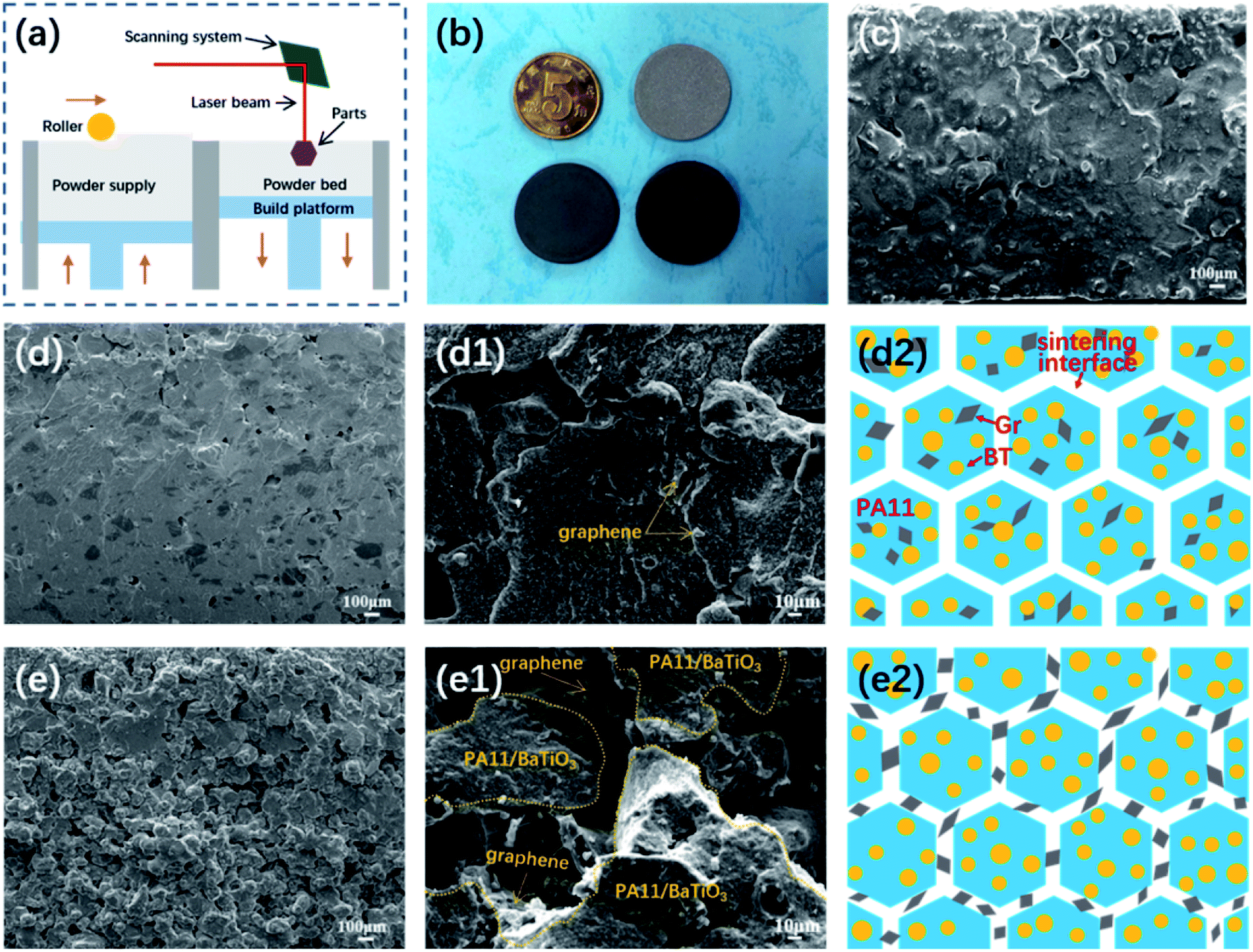 | ||
| Fig. 4 (a) Schematic of the selective laser sintering process. (b) Optical images of the PA11/BT, PA11/BT/Gr, and PA11/BT/Gr-coating parts fabricated by SLS. SEM images of the fractured surface of the (c) PA11/BT parts, (d and d1) PA11/BT/Gr parts, and (e and e1) PA11/BT/Gr-coating parts at different magnifications. The schematic illustration of the location of BT and graphene nanoparticles in the SLS-printed (d2) PA11/BT/Gr and (e2) PA11/BT/Gr-coating parts. | ||
More importantly, graphene in the PA11/BT/Gr-coating parts were mainly distributed at the interface of the adjacent particles, as shown in Fig. 4(e1). During the SLS processing of the PA11/BT/Gr-coating powders, the PA11 melt coalesced with adjacent particles without significantly changing the morphology of graphene. Therefore, the graphene could remain at the sintering interface and form a discontinuous graphene network (Fig. 4(e2)). It is worth noting that the content of graphene coated on the powder surface was small (only 0.35%). Once the content of graphene increased and connected into the conductive networks, the ceramic particles cannot be polarized by the applied external electric field and show no piezoelectric performance. However, graphene was keen to aggregate locally in the sintering interface during the melting of the polymer particles. These aggregates cut off the conductive network and avoid the electrostatic breakdown. Therefore, the graphene network constructed in the PA11/BT/Gr-coating part was discontinuous, which showed enhanced dielectric and piezoelectric properties. The related models and principles will be discussed in detail later.
3.3. Dielectric properties
The frequency-dependent dielectric constant (εr) and dielectric loss of all samples measured at ambient temperature in the range of 102 to 106 Hz are shown in Fig. 5(a) and (b), respectively. The dielectric constant of the three kinds of nanocomposites decreased with the increase of frequency over the entire frequency range, which was attributed to the Maxwell–Wagner–Sillars (MWS) interfacial polarization and space charge polarization.39 The dielectric constant increased with the addition of graphene nanoparticles and the PA11/BT/Gr-coating parts showed a higher dielectric constant than the PA11/BT/Gr parts loaded in the whole range of frequency. At the frequency of 1000 Hz, the dielectric constant of the PA11/BT/Gr-coating parts was 18.7, which was approximately 1.6 times that of the PA11/BT/Gr parts. The increase in the dielectric constant was attributed to the formation of many micro-capacitors inside the nanocomposites.40 As shown in Fig. 5(b), over most frequency ranges, the dielectric loss increased with the addition of graphene, and the PA11/BT/Gr-coating parts showed a higher dielectric loss than the PA11/BT/Gr parts. The PA11/BT/Gr-coating powders would result in porosity in the sintered part, and thus causes the generation of a leakage current.41 Although the dielectric loss of the PA11/BT/graphene ternary nanocomposites increased with the construction of the discontinuous graphene network, the maximum dielectric loss was only 0.04 at 100 Hz, which had little effect on the dielectric properties.42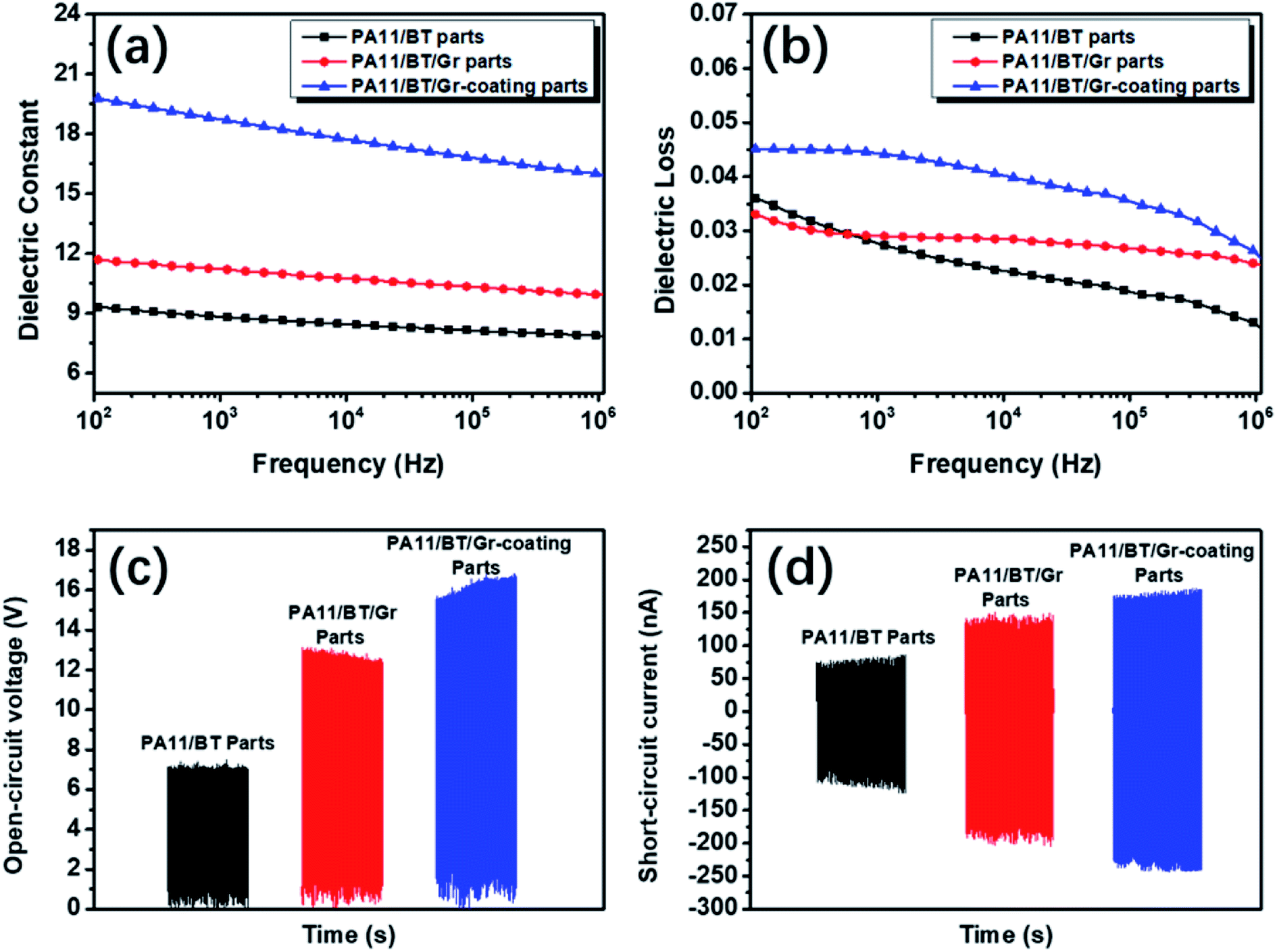 | ||
| Fig. 5 Dielectric and piezoelectric properties of different piezoelectric parts fabricated by the SLS process; frequency dependence of the (a) dielectric constant and (b) dielectric loss of different parts; (c) open-circuit voltage and (d) corresponding short-circuit current, respectively, generated by different parts under the linear motor at the acceleration of 5 m s−2. | ||
According to Fig. 4(e2), a micro-capacitor model was proposed to explain the crucial role of the discontinuous graphene network constructed by SLS.43 The micro-capacitor was made of graphene and the PA11 matrix, which acted as electrodes and a dielectric layer between the two adjacent electrodes, respectively. Unlike the PA11/BT/Gr parts with uniformly distributed graphene (Fig. 4(d2)), the graphene in the PA11/BT/Gr-coating parts were mainly dispersed separately on the sintering interface. The formation of this discontinuous graphene network increased the local concentration of graphene, and then the closer conductive fillers caused more micro-capacitors to be formed inside the composite material. The reduction of the distance between the two electrodes of the micro-capacitors can cause a significant increase in the capacitance, as well as the dielectric constant.
3.4. Piezoelectric properties
The BaTiO3 nanoparticles still showed ferroelectric properties after the heating and cooling process of SLS (Fig. S2†). Under the same poling conditions, the piezoelectric strain coefficient d33 values of the PA11/BT parts and PA11/BT/Gr parts were 1.6 pC N−1 and 2.5 pC N−1, respectively, while the PA11/BT/Gr-coating parts showed the highest d33 value of 3.8 pC N−1, which was approximately 52% higher than the PA11/BT/Gr parts. Because separated graphene at the sintering interface improved the local electric field acting on the ceramic particles and the discontinuous graphene network provided more conducting percolation routes in the composite material,44 the effective voltage of the piezoelectric material during polarization was increased and made the ferroelectric domains more orderly. Therefore, the PA11/BT/Gr-coating parts showed enhanced piezoelectric properties.Piezoelectric materials can convert mechanical stress to electric voltage, and the open-circuit voltage and short-circuit current are two important indicators of piezoelectric parts in the mechanical-to-electrical conversion process. Fig. 5(c) and (d) showed the open-circuit voltage and the corresponding short-circuit current generated by the PA11/BT, PA11/BT/Gr and PA11/BT/Gr-coating parts under the linear motor at the acceleration of 5 m s−2. Clearly, the open-circuit voltage and short-circuit current of the sintered parts increased with the addition of graphene. The PA11/BT/Gr-coating parts showed a better piezoelectric output performance than the PA11/BT/Gr parts. The open-circuit voltage and the short-circuit current of the PA11/BT/Gr-coating parts reached 16.2 ± 0.4 V and 234.8 ± 6.0 nA, respectively, which was better than the other studies on the piezoelectric output performance of the polymer/ceramic composites, as shown in Table 4. It could be seen that the PA11/BT/Gr-coating parts we designed and fabricated showed better comprehensive piezoelectric output performance than those of most reported piezoelectric composites. On the one hand, the discontinuous graphene network constructed by graphene coating and zero-shear SLS processing improved the dielectric properties by forming micro-capacitors, leading to enhanced piezoelectric properties of the composite. On the other hand, the microporous structures generated by SLS technology could further magnify the pressure sensitivity, making the piezoelectric output higher.
| Composite | Preparation method | Piezoelectric output | Ref. |
|---|---|---|---|
| PA11/BT/Gr-coating parts | SLS | 16.2 ± 0.4 V, 234.8 ± 6.0 nA | This study |
| PVDF/BT films | EPAM | 0.0442 nA | 45, by H. Kim |
| PVDF/BT discs parts | Hot pressing | 6 V | 46, by D. Olmos |
| BaTiO3/CNT NCG | Dispersed in PDMS | 3 V, 300 nA | 47, by K. I. Park |
| PVDF/BT films | FDM | 0.15 nA | 48, by H. Kim |
| PEGDA/BT + TMSPM | Digital projection printing | 0.5 V | 49, by K. Kim |
4. Conclusions
The graphene-coated PA11/BT ternary nanocomposite powders, combining the excellent piezoelectric properties of piezoelectric ceramics (BT), the excellent SLS processing and mechanical properties of PA11, and the excellent electrical properties of Gr, were prepared through the solid-state shear milling technology and ultrasonic technology, which had a wider sintering window of 15.3 °C and an improved powder flowability for the SLS process. The unique discontinuous graphene network and microporous structures in the PA11/BT/Gr-coating parts were constructed by SLS technology due to its zero-shear processing. The discontinuous graphene network significantly increased the dielectric constant and the piezoelectric coefficient, while the porous structure further magnified the stress concentration. As a result, the open-circuit voltage and short-circuit current of the PA11/BT/Gr-coating parts reached 16.2 ± 0.4 V and 234.8 ± 6.0 nA, which showed better comprehensive performance than many reported piezoelectric materials. This work not only managed to prepare piezoelectric materials with high output performance, but also opened up a new scope for 3D configuration design in piezoelectric materials.Conflicts of interest
There are no conflicts to declare.Acknowledgements
This work is supported by the National Natural Science Foundation of China (51933007 and 51433006).References
- Y. You, W. Liao, D. Zhao, H. Ye, Y. Zhang, Q. Zhou, X. Niu, J. Wang, P. Li and D. Fu, Science, 2017, 357, 306–309 CrossRef CAS PubMed.
- Y. Zhang, W. Zhu, C. K. Jeong, H. Sun, G. Yang, W. Chen and Q. Wang, RSC Adv., 2017, 7, 32502–32507 RSC.
- C. Dagdeviren, P. Joe, O. L. Tuzman, K. I. Park and J. A. Rogers, Extreme Mech. Lett., 2016, 9, 269–281 CrossRef.
- J. Khaliq, D. B. Deutz, J. A. C. Frescas, P. Vollenberg, T. Hoeks, S. van der Zwaag and P. Groen, Ceram. Int., 2017, 43, 2774–2779 CrossRef CAS.
- J.-F. Capsal, E. Dantras, L. Laffont, J. Dandurand and C. Lacabanne, J. Non-Cryst. Solids, 2010, 356, 629–634 CrossRef CAS.
- H. Parangusan, D. Ponnamma and M. A. A. AlMaadeed, RSC Adv., 2017, 7, 50156–50165 RSC.
- D. Carponcin, E. Dantras, L. Laffont, J. Dandurand, G. l. Aridon, F. Levallois, L. Cadiergues and C. Lacabanne, J. Non-Cryst. Solids, 2014, 388, 32–36 CrossRef CAS.
- A. Jain, K. J. Prashanth, A. K. Sharma, A. Jain and P. N. Rashmi, Polym. Eng. Sci., 2015, 55, 1589–1616 CrossRef CAS.
- F. A. He, K. H. Lam, J. T. Fan and L. W. Chan, Polym. Test., 2013, 32, 927–931 CrossRef CAS.
- L. Huang, C. Lu, F. Wang and L. Wang, RSC Adv., 2014, 4, 45220–45229 RSC.
- V. Bhavanasi, V. Kumar, K. Parida, J. Wang and P. S. Lee, ACS Appl. Mater. Interfaces, 2015, 8, 521–529 CrossRef PubMed.
- Y. Shen, Y. Lin, M. Li and C. W. Nan, Adv. Mater., 2007, 19, 1418–1422 CrossRef CAS.
- J. Wang, N. Wei, F. Wang, C. Wu and S. Li, Polym. Bull., 2012, 68, 2285–2297 CrossRef CAS.
- P. Zhao, S. Wang, A. Kadlec, Z. Li and X. Wang, Ceram. Int., 2016, 42, 15030–15034 CrossRef CAS.
- X. Zha, T. Li, R. Bao, L. Bai, Z. Liu, W. Yang and M. Yang, Compos. Sci. Technol., 2017, 139, 17–25 CrossRef CAS.
- J. Du, L. Zhao, Y. Zeng, L. Zhang, F. Li, P. Liu and C. Liu, Carbon, 2011, 49, 1094–1100 CrossRef CAS.
- S. Yuan, F. Shen, C. K. Chua and K. Zhou, Prog. Polym. Sci., 2019, 91, 141–168 CrossRef CAS.
- Y. Yu, Y. Guo, T. Jiang, K. Jiang, J. Li and S. Guo, RSC Adv., 2017, 7, 23176–23181 RSC.
- Z. Li, Z. Wang, X. Gan, D. Fu, G. Fei and H. Xia, Macromol. Mater. Eng., 2017, 302, 1700211 CrossRef.
- P. Adhikary, S. Garain and D. Mandal, Phys. Chem. Chem. Phys., 2015, 17, 7275–7281 RSC.
- Y. Mao, P. Zhao, G. McConohy, H. Yang, Y. Tong and X. Wang, Adv. Energy Mater., 2014, 4, 1301624 CrossRef.
- Z. Zhang, C. Yao, Y. Yu, Z. Hong, M. Zhi and X. Wang, Adv. Funct. Mater., 2016, 26, 6760–6765 CrossRef CAS PubMed.
- H. Chung and S. Das, Mater. Sci. Eng., A, 2008, 487, 251–257 CrossRef.
- K. Monri and S. Maruo, Sens. Actuators, A, 2013, 200, 31–36 CrossRef CAS.
- W. Shao, W. Qi and M. Hong, Polym. Int., 2010, 54, 336–341 CrossRef.
- X. Xu, Q. Wang, X. Kong, X. Zhang and J. Huang, Plast., Rubber Compos. Process. Appl., 1996, 25, 152–158 CAS.
- C. Zhou, W. Ke and F. Qiang, Polym. Int., 2009, 58, 538–544 CrossRef CAS.
- W. Shao, Q. Wang, F. Wang and Y. Chen, Carbon, 2006, 44, 2708–2714 CrossRef CAS.
- H. Pang, T. Chen, G. Zhang, B. Zeng and Z.-M. Li, Mater. Lett., 2010, 64, 2226–2229 CrossRef CAS.
- H. Hu, G. Zhang, L. Xiao, H. Wang, Q. Zhang and Z. Zhao, Carbon, 2012, 50, 4596–4599 CrossRef CAS.
- M. Li, C. Gao, H. Hu and Z. Zhao, Carbon, 2013, 65, 371–373 CrossRef CAS.
- H. Chung and S. Das, Mater. Sci. Eng., A, 2006, 437, 226–234 CrossRef.
- Y. F. Zhu, L. Zhang, T. Natsuki, Y. Q. Fu and Q. Q. Ni, ACS Appl. Mater. Interfaces, 2012, 4, 2101–2106 CrossRef CAS PubMed.
- P. Sedykh and D. Michel, Phys. Rev. B: Condens. Matter Mater. Phys., 2009, 79, 134119 CrossRef.
- I. Gibson and D. Shi, Rapid Prototyp. J., 1997, 3, 129–136 CrossRef.
- R. Freeman, Powder Technol., 2007, 174, 25–33 CrossRef CAS.
- W. R. McCall, K. Kim, C. Heath, G. La Pierre and D. J. Sirbuly, ACS Appl. Mater. Interfaces, 2014, 6, 19504–19509 CrossRef CAS PubMed.
- S. Cha, S. M. Kim, H. Kim, J. Ku, J. I. Sohn, Y. J. Park, B. G. Song, M. H. Jung, E. K. Lee and B. L. Choi, Nano Lett., 2011, 11, 5142–5147 CrossRef CAS PubMed.
- M. Samet, V. Levchenko, G. Boiteux, G. Seytre, A. Kallel and A. Serghei, J. Chem. Phys., 2015, 142, 194703 CrossRef CAS PubMed.
- F. He, S. Lau, H. L. Chan and J. Fan, Adv. Mater., 2009, 21, 710–715 CrossRef CAS.
- J. Zhu, X. Ji, M. Yin, S. Guo and J. Shen, Compos. Sci. Technol., 2017, 144, 79–88 CrossRef CAS.
- C. Yang, Y. Lin and C. Nan, Carbon, 2009, 47, 1096–1101 CrossRef CAS.
- X. Xia, J. Chen, G. Liu, M. S. Javed, X. Wang and C. Hu, Carbon, 2017, 111, 569–576 CrossRef CAS.
- M. Sharma, V. Srinivas, G. Madras and S. Bose, RSC Adv., 2016, 6, 6251–6258 RSC.
- H. Kim, F. Torres, D. Villagran, C. Stewart, Y. Lin and T. L. B. Tseng, Macromol. Mater. Eng., 2017, 302, 1700229 CrossRef.
- D. Olmos, G. González-Gaitano, A. Kholkin and J. González-Benito, Ferroelectrics, 2013, 447, 9–18 CrossRef CAS.
- K. I. Park, M. Lee, Y. Liu, S. Moon, G. T. Hwang, G. Zhu, J. E. Kim, S. O. Kim, D. K. Kim and Z. L. Wang, Adv. Mater., 2012, 24, 2999–3004 CrossRef CAS PubMed.
- H. Kim, T. Fernando, M. Li, Y. Lin and T.-L. B. Tseng, J. Compos. Mater., 2018, 52, 197–206 CrossRef CAS.
- K. Kim, W. Zhu, X. Qu, C. Aaronson, W. R. McCall, S. Chen and D. J. Sirbuly, ACS Nano, 2014, 8, 9799–9806 CrossRef CAS PubMed.
Footnote |
| † Electronic supplementary information (ESI) available. See DOI: 10.1039/d0ra01042a |
| This journal is © The Royal Society of Chemistry 2020 |