 Open Access Article
Bubble-propelled micromotors based on hierarchical MnO2 wrapped carbon nanotube aggregates for dynamic removal of pollutants†
Xiukai Wu‡
a,
Ling Chen‡a,
Chan Zheng *ab,
Xinxin Yana,
Pingqiang Daia,
Qianting Wanga,
Wei Liab and
Wenzhe Chena
aSchool of Materials Science and Engineering, Fujian University of Technology, 3 Xueyuan Road, Fuzhou 350108, PR China. E-mail: czheng.fjut@gmail.com
bInstitute of Materials Surface Technology, 3 Xueyuan Road, Fuzhou 350108, PR China
First published on 14th April 2020
Abstract
Water pollution is currently an urgent public health and environmental issue. Bubble-propelled micromotors might offer an effective approach for dealing with environmental contamination. Herein, we present the synthesis of multi-walled carbon nanotube (MWCNT)/manganese dioxide (MnO2) micromotors based on MWCNT aggregates as microscale templates by a simple one-step hydrothermal procedure. The morphology, composition, and structure of the obtained MWCNT/MnO2 micromotors were characterized in detail. The MnO2 nanoflakes formed a catalytic layer on the MWCNT backbone, which promoted effective bubble evolution and propulsion at remarkable speeds of 359.31 μm s−1. The bubble velocity could be modulated based on the loading of MnO2 nanoflakes. The rapid movement of these MWCNT/MnO2 catalytic micromotors resulted in a highly efficient moving adsorption platform, which considerably enhanced the effectiveness of water purification. Dynamic adsorption of organic dyes by the micromotors increased the degradation rate to approximately 4.8 times as high as that of their corresponding static counterparts. The adsorption isotherms and adsorption kinetics were also explored. The adsorption mechanism was well fitted by the Langmuir model, following pseudo-second-order kinetics. Thus, chemisorption of Congo red at the heterogeneous MnO2 wrapped microimotor surface was the rate determining step. The high propulsion speed and remarkable decontamination efficiency of the MWCNT/MnO2 micromotors indicate potential for environmental contamination applications.
1. Introduction
Inspired by molecular motors and mobile organisms, scientists have used both top-down and bottom-up strategies to fabricate propelled micromotors in recent decades owing to their small dimensions and accessibility to tiny and complex environments. Such systems have extensive practical applications in the fields of drug delivery, microsurgery, environmental remediation, energy devices, and sensing and detection.1–6 Generally, autonomous propulsion of microscale objects can be achieved by several mechanisms, including catalytic chemical reactions, light, ultrasound, and magnetic and electric fields. Among the variety of microscale machines, particular attention has been paid to chemically powered micromotors, which can convert chemical energy into mechanical kinetic energy and promote motor movement. Various self-propelled micromotors have been developed based on the mechanisms of surface tension gradients, self-electrophoresis, self-diffusiophoresis, and bubble propulsion.7,8 Bubble-propelled micromotors are particularly attractive owing to their properties, such as high-power output, robust performance, and high speed in ionic-strength solution.9,10To form bubble-induced propulsion micromotors, an asymmetrical structure is crucial to generating the direction of movement. Various bubble-induced micromotors, based on different fuels, have been developed through asymmetrical design of the shape and/or composition of particles leading to self-phoresis.11,12 Many structures, including micro/nano tubes, nanorods, and Janus spheres, have been developed that contain a layer of catalyst to produce bubbles for propulsion.13–15 Generally, tubular micromotors are fabricated by either roll-up nanotechnology or template-assisted synthesis.8,16 Spherical micromotors are fabricated with the use of solid spheres in which a layer of a material is deposited by physical vapor deposition techniques to make Janus particles.8,17 The above-mentioned methods not only involve multiple steps but also require expensive equipment. Therefore, a simple and cost-effective technique to obtain micromotors, preferably with multi-responsiveness, is needed. To date, only a few one-step and simple fabrication strategies to obtain multifunctional micromotors have been reported.18,19
Carbon nanotubes (CNTs) are a representative one-dimensional material that has been actively studied owing to excellent mechanical, electrical, chemical, and thermal properties for a variety of potential applications.20–22 CNTs have a large specific surface area up to 200 m2 g−1 and hence tend to agglomerate and form clusters owing to van der Waals forces.22 The random distribution of volumes in the aggregates form natural asymmetric structures that can serve as a candidate template for constructing bubble-propelled micromotors. Recent reports have confirmed that carbon nanomaterials, such as CNTs and graphene are efficient micromotors owing to their excellent thermal conductivities, large surface areas, and good biocompatibility.23–26 For example, balloon-like MnOx–graphene synthesized via an evaporation induced self-assembly and ultrasonic spray pyrolysis method has been used as a “chemical taxi”.23 Highly efficient tubular micromotors based on combinations of fullerene, carbon nanotubes, and graphene carbon black with Pt, Pd, Ag, or MnO2 catalytic layers have been confirmed to show propulsion in different media.24
Catalysts are important for generating movement from bubble-propelled micromotors. Various materials have been developed as catalysts to produce the gas bubbles necessary to provide a driving force for motion, including platinum, palladium, silver, magnesium, manganese dioxide (MnO2), and enzymes.5,27 Among these, MnO2 is currently considered to be the most promising candidate material for micromotor fabrication because of its excellent catalytic properties, simple synthesis, low cost, chemical stability, environmental friendliness, and natural abundance.28,29 Fundamental investigations have also shown that micromotors based on MnO2 as a catalyst have a dual functionality, autonomous motion, and the ability to degrade organic molecular dyes, such as rhodamine 6 and methylene blue, in contaminated media by a Fenton like mechanism.30–32 Consequently, these materials hold great promise for applications in water remediation.
Herein, we present the synthesis of micromotors based on multi-walled carbon nanotube (MWCNT) aggregates as microscale templates by a simple hydrothermal procedure, as shown in Scheme 1. It is noted that our strategy presented here is facile and cost-effective against the existing methods using to prepare CNTs-Fe2O3/MnO2 tubular micromotors and MnO2/reduced graphene oxide hydrogel motors, which tend to comprise troublesome multistep processes and sometimes require the utilization of expensive equipment, and therefore greatly hinder the further development of micromotors for practical applications.26,33 Moreover, the inherent asymmetric structures of MWCNTs agglomeration make it more readily to synthesize bubble-propelled micromotors as compared with other carbon-based materials. Specially, nanoflakes of MnO2 were loaded onto the surface of MWCNTs by redox reactions and acted as catalyst that could be efficiently decomposed into hydrogen peroxide to generate O2, which induced propulsion of the micromotor. Propulsion characterization demonstrated the nanoflakes MnO2 wrapped micromotors exhibited a high movement speed and the speed could be modulated based on the loading of MnO2. In addition, this unique micromotor enabled 80.7% degradation of 40 mg L−1 Congo red within 10 min in the presence of 3% H2O2. Adsorption isotherms and adsorption kinetics were also investigated. Overall our developed strategy allows for simple, low-cost, and direct synthesis of micromotors that have potential for practical environmental applications.
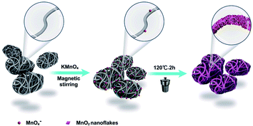 | ||
| Scheme 1 Schematic diagram of the synthesis of the bubble-propelled MWCNT/MnO2 micromotor with MWCNT aggregates as microscale templates. | ||
2. Experimental
2.1 Materials
MWCNTs were purchased Nanjing XFNANO Materials Tech Co., Ltd (Nanjing, China), with a diameter of 30–60 nm and length of 5–15 μm. KMnO4 was purchased from Aldrich and used without further purification. All other chemicals and solvents were of analytical grade. Deionized water was used in all aqueous solutions.2.2 Fabrication of MWCNT/MnO2 micromotors
The MWCNT/MnO2 micromotors were fabricated by a standard hydrothermal method, in which MWNCT asymmetric aggregates acted as templates. A typical synthesis process is described as follows. First, 42 mg of MWCNTs were ultrasonically dispersed in 30 mL of DI water for 20 min to obtain a homogeneous suspension. Then, 110.6 mg of KMnO4 was added into the above suspension and stirred with a glass rod for 2 min. The reaction mixture was charged into a reaction kettle and maintained at 120 °C for 0.5, 1, or 2 h, and the resulting micromotor samples are denoted as MWCNT/MnO2-0.5, MWCNT/MnO2-1 and MWCNT/MnO2-2, respectively. Finally, the suspension was filtered, washed several times with deionized water, and the filter cake was dried in an oven at 60 °C for 6 h. The resulting black powders were collected and micromotors were obtained.2.3 Morphology and structure characterization
The morphology and element distributions of the spawn-shaped micromotors were examined with a field-emission scanning electron microscope (FESEM; JEOL JSM-6700, JEOL Ltd., Tokyo, Japan) equipped with an Oxford X-MAN energy dispersive X-ray (EDX) spectrometer. For SEM observations, Au was sputtered on the sample surface. The detailed morphology was further imaged with a transmission electron microscope (TEM; JEM-2010, accelerating voltage 200 kV). The samples were ultrasonicated in ethanol to ensure dispersion. A drop of the dispersed sample was left to dry on a commercial carbon-coated Cu TEM grid. Crystallographic information was obtained by X-ray diffraction (XRD; Bruker D8-Advance X-ray diffractometer) with a Cu Kα radiation source (λ = 1.5418 Å), at 40 kV and 30 mA. The 2θ range was 10° to 90°. Raman spectra of the micromotors were measured with a Raman spectrometer (Renishaw Invia) at ambient temperature with an excitation wavelength of 785 nm. X-ray photoelectron spectroscopy (XPS, Escalab 250, Thermo Fisher Scientific Co.) was based on Al Kα radiation as the excitation source. The binding energy of each element was corrected to the standard C 1s contamination peak (284.8 eV). The pore structures of the assembled architectures were investigated at 77 K on the basis of nitrogen adsorption isotherms obtained with a surface area and porosimetry analyzer (Micromeritics 3Flex surface area and porosimetry analyzer). The samples were degassed at 120 °C for 10 h before the measurements.2.4 Motion characterization of micromotors
An optical microscope (E100, Nikon, China), coupled with a high-speed digital camera (PSC601-10C, OPLENIC, China), was applied to capture the movement characteristic of the micromotors. To record the videos, a suspension containing micromotors was dropped onto a glass slide, followed by addition of 7.5% H2O2. The speed and tracking of the micromotors were calculated from the recorded videos with tracking software.2.5 Degradation of Congo red
To explore the applicability of the MWCNT/MnO2 micro motors to wastewater treatment, we performed degradation experiments with Congo red as a contaminant representative. During the Congo red degradation experiment, micromotors (∼20 mg) were dispersed into Congo red solution (40 mg L−1) containing 2 mL H2O2 solution (3%). A UV-Vis spectrometer (UV-2600, Shimadzu) was used to monitor the absorbance of the solutions. The samples were placed in a quartz cell with an optical path length of 1 cm.3. Results and discussion
3.1 Characterization of MWCNT/MnO2 micromotors
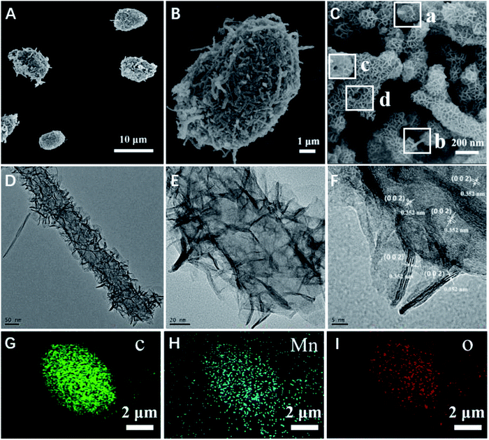
The micromotors were fabricated with the use of MWCNT aggregates as a template, which produced a unique asymmetric structure owing to the many pores formed by the entangled carbon nanotubes. The asymmetric nature of this structure contributed to the propulsion of the obtained micromotors. The morphology of the resulting micromotors was characterized and is shown in Fig. 1. The micromotors were approximately 10 μm in length and 5 μm diameter with a well-defined quasi-oval geometry (Fig. 1A). Hence, the hydrothermal procedure did not affect the original morphology of the MWCNT aggregates. An individual micromotor, shown in Fig. 1B, indicates successful loading of two-dimensional nanoflakes onto the MWCNT surface and the MWCNTs were completely covered by the nanoflakes (Fig. 1C), giving the micromotors a highly rough surface. Notably, the MWCNTs were still detected after a redox reaction for 2 h, as confirmed by the square frames a and b in Fig. 1C. Furthermore, the tubular structure of the MWCNTs was also maintained during the redox procedure (square frames c and d in Fig. 1C). These results suggest that although the outer surface of the MWCNTs acted as a scaffold for formation of nanoflakes, the MWCNTs were preserved after the redox reaction.To fully investigate the surface characteristics and morphology of the decorated nanoflake structure, we performed detailed TEM and high resolution TEM (HRTEM). The TEM images further indicated the growth of two-dimensional flaked structures over the MWCNT surface (Fig. 1D and E). Fig. 1F shows a HRTEM image of the square section in Fig. 1C. The lattice interplanar spacing of 0.352 nm was indexed to the spacing of the (200) plane of birnessite-type MnO2. EDS elemental mapping analysis also confirmed the distribution of C, Mn, and O in the as synthesized micromotors (Fig. 1G and H), indicating that the nanoflakes were mainly composed of MnO2. The MnO2 nanoflakes increased the specific surface area (SSA) of the MWCNT/MnO2-2 composite (103.1898 cm2 g−1) by approximately 10% compared with that of the pristine template MWNCTs (90.9064 cm2 g−1). These textural characteristics contributed to fast adsorption kinetics and efficient propulsion of the resulting mobile adsorption platforms.
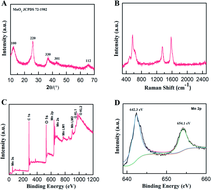
The structure and composition of the MWCNT/MnO2 micromotors were further explored. The XRD patterns of the as-synthesized micromotors (Fig. 2A) contained four distinct diffraction peaks at 12°, 24°, 37°, and 65° that were indexed to the (001), (002), (111), and (020) planes of birnessite-type MnO2 (JCPDS 72-1982, δ-MnO2), respectively, consistent with the HRTEM results. The structures of the micromotors were also characterized by the Raman spectroscopy. As shown in Fig. 2B, the presence of a G (1580 cm−1) band and D (1345 cm−1) band in the range 0 to 2500 cm−1, strongly confirmed the existence of the MWCNTs. A characteristic band centered at 640 cm−1 was also detected, which is assigned to the symmetric stretching vibration of ν2(Mn–O) in the MnO6 groups.34,35 Quantitative elemental analysis of the micromotors was conducted by XPS. The survey spectrum (Fig. 2C) revealed the presence of carbon (C 1s peak), oxygen (O 1s peak, O Auger peaks), and manganese (Mn 2p, Mn 2s, and Auger peaks) in the micromotors. The fitted Mn 2p spectrum of the micromotors (Fig. 2D) showed two peaks centered at 654.1 and 642.3 eV, assigned to Mn 2p3/2 and Mn 2p1/2, respectively. The splitting between these two bands was 11.8 eV, indicating that Mn4+ formed predominantly in the MnO2.36 Therefore, the formation mechanism of MnO2 can be explained by the following reaction:
| 4MnO4− + 3C + H2O → 4MnO2 + CO32− + 2HCO3− | (1) |
Various carbon materials, including activated carbon, carbon nanotubes, carbon fibers, and graphene have been used as scaffolds to form MnO2 composites based on in situ reactions between MnO4− and carbon.37–40 The reduction of MnO4− produces birnessite-type manganese oxide, which is a layered manganese oxide composed of [MnO6] octahedra sharing edges. Thus, we successfully fabricated a new MWCNT/MnO2 micromotor that had a well-defined crystal structural and a high SSA. The simple synthesis, based on MWCNT aggregates as a template in a one-step hydrothermal procedure, produced a material with propulsion properties and good catalytic performance. Furthermore, the facile and efficient strategy can be readily extended to prepared other carbon-based nanomaterials through in situ reactions between MnO4− and carbon, and therefore promote the applications of carbon allotrope nanomaterials in fields of optoelectronics, environment, biology, medicine, and energy.
3.2 Self-propelled motion of MWCNT/MnO2 micromotors
Generally, a rough surface favors generation of microbubbles. Consequently, a rough catalytic surface induced by MnO2 nanoflakes considerably promotes effective bubble evolution and propulsion of micromotors. The propulsion performance of MWCNT/MnO2 micromotors was experimentally explored and time-lapse images are shown in Fig. 3 (Fig. 3B taken from Videos S1, S2, and S3, respectively). Notably, all the motion characterizations were performed in absence of any surfactant although surfactant can decrease the interfacial free energy and thus facilitate bubble formation and release from the micromotors.41 Compared with tubular micromotors, the MWCNT/MnO2 micromotors with oval structure display smaller interfacial tension and the catalytic materials are located on the surface of micromotors, which would facilitate bubble generation and bubble detachment.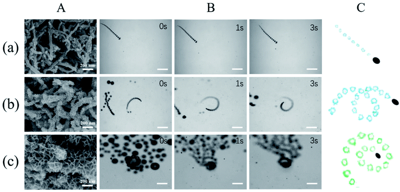 | ||
| Fig. 3 Propulsion performance of MWCNT/MnO2 micromotors loading with different quantity of nanoflakes MnO2. (A) SEM images of (a) MWCNT/MnO2-0.5, (b) MWCNT/MnO2-1, and (c) MWCNT/MnO2-2 micromotors; (B) time-lapse images (taken from ESI Videos S1–S3†) of the motion of (a) MWCNT/MnO2-0.5, (b) MWCNT/MnO2-1, and (c) MWCNT/MnO2-2 micromotors in the presence of 7.5% H2O2. Scale bars, 200 μm. (C) Corresponding tracking lines of (a) MWCNT/MnO2-0.5, (b) MWCNT/MnO2-1, and (c) MWCNT/MnO2-2 micromotors. | ||
The micromotors with active nanoflakes MnO2 on the surface were used as catalysts for the decomposition of H2O2 to produce oxygen that was released from one side of the micromotors. Bubble-propelled micromotors typically have a tubular or spherical shape with an asymmetrical structure. For tubular micromotors, a catalytic component that triggers decomposition of H2O2 is included inside the tubes. The underlying mechanism involves the formation and continuous ejection of oxygen bubbles from the tubular confinement, inducing motion in the opposite direction.42 For spherical micromotors, for example, Janus motors, the motion is mainly attributed to asymmetric generation of bubbles achieved by a partially inert coating.43 However, the MWCNT/MnO2 micromotors used here were oval and symmetric, therefore the self-driven motion of micromotors might be attributed to asymmetric forces induced by the homogeneous distribution of the MnO2 catalyst coating. The MWCNT aggregates formed a large amount of randomly intertwined carbon tubes that created voids of irregular shape and size. The coating of the MnO2 catalytic nanoflakes did not alter the inhomogeneity of the volumes in the micromotors. Consequently, the decomposition of H2O2 led to unbalanced generation of oxygen gas bubbles in the micromotors, causing an anisotropic distribution of the drag forces, finally resulting in mobility of the micromotors.
Generally, the motion of a bubble-propelled micromotor is determined by its size, shape, geometry, the amount of catalyst loaded onto the surface, and the concentration of fuel used.8–11 Three typical kinds of trajectories were identified for the motion of the MWCNT/MnO2 catalytic micromotors: linear, helical, and self-rotating (Fig. 3C). Fig. 3B and corresponding ESI Videos S1, S2, and S3,† respectively show time-lapse images of the three micromotor systems, MWCNT/MnO2-0.5, MWCNT/MnO2-1, and MWCNT/MnO2-2, in a 7.5% H2O2 solution without the addition of any surfactant. Because bubble formation takes places both outside and inside the MWCNT/MnO2 micromotors, a long fine trail of oxygen bubbles is generated from catalytic decomposition of H2O2. For MWCNT/MnO2-0.5, the trajectory was almost linear, as shown in Fig. 3A, whereas for MWCNT/MnO2-1 and MWCNT/MnO2-2, the trajectory was helical and self-rotating. Owing to decomposition of H2O2 at the different surfaces of the microstructure and inner pores, these micromotors experienced unbalanced bubble generation and an unequal propelling force, which contributed to the irregular motion.
As expected, the speed of the MWCNT/MnO2 micromotor strongly depended on the loading of the MnO2 nanoflakes. The velocities of the MWCNT/MnO2-0.5, MWCNT/MnO2-1, and MWCNT/MnO2-2 micromotors were 67.67, 228.19, and 359.31 μm s−1, respectively. Previous investigations have confirmed that the speed of tubular carbon-based micromotors depends on a balance between different morphological properties of the micromotors, namely, the outer surface roughness and the inner wall micromotor structure.24 Higher roughness results in a greater frictional force between the moving micromotor and surrounding fluid, which hampers micromotor movement. In the current study, the MWCNT/MnO2-2 micromotor had the highest surface roughness, which caused a high frictional force; however, the motion of the MWCNT/MnO2-2 micromotor was also the highest. Consequently, the velocity of the MWCNT/MnO2 micromotors mainly depended on the inner structural characteristics. Extension of the hydrothermal reaction time caused more catalytic MnO2 nanoflakes to be loaded on the surface of the MWCNT aggregates, as confirmed by the SEM imaging (Fig. 3A). Therefore, these micromotors are expected to provide a large catalytic surface area and improve fuel accessibility and leading to remarkably efficient propulsion. Therefore, modulating the loading nanoflakes MnO2 enhanced the propulsion performance.
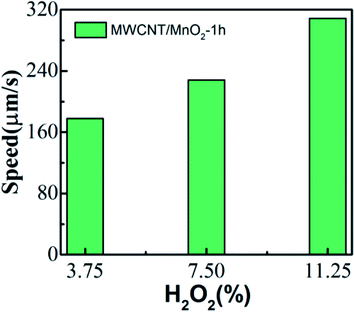
The speed of the micromotor is also dependent on the concentration of the chemical fuel. The MWCNT/MnO2 catalytic micromotors were dispersed into 3.75, 7.5, and 11.25% H2O2 solution, and the velocity was calculated according to the micromotor position on the moving route (Videos S4, S2, and S5†). As illustrated in Fig. 4, the average speed of micromotors increases from 177.81 μm s−1 at 3.75% H2O2 to 308.72 μm s−1 at 11.25% H2O2. Clearly, MWCNT/MnO2 micromotors show increased velocities with increasing fuel concentration. Hence, the mobility of the MWCNT/MnO2 micromotors depend on both the fuel concentration and loading of nanoflakes MnO2.
3.3 Dye degradation of the MWCNT/MnO2 micromotors
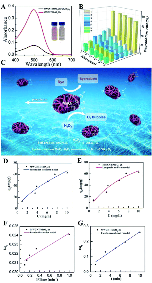
Previous reports have indicated that self-propelled MnO2 micromotors can be used for motion-assisted Fenton-like degradation of organic pollutants.30–32 To explore the practical decontamination capability of the MWCNT/MnO2 micromotors, associated with their movement and resulting mixing, we examined their ability to degrade Congo red. Congo red is a commonly used organic dye, which appears red in oxidized form and colorless in reduced form, and can be used as a contaminant to investigate the activity of micromotors in pollution degradation processes. Mixtures of hydrogen peroxide and Congo red without any surfactant were prepared as target waste water, and the degradation results are shown in Fig. 5A and B. The absence of surfactant is owing to the fact that the degradation speed of the MWCNTs/MnO2 micromotors is too fast. Adding surfactant would make it difficult to observe the changes during the degradation. The sharp decrease in the absorbance signal of Congo red following the motor treatment with the addition of 3% H2O2 fuel indicated the effectiveness of the micromotor movement (Fig. 5A). Importantly, the Congo red become colorless after treated with MWCNT/MnO2 micromotors in 3% H2O2 in 10 min (as shown in inserted photo in Fig. 5A). As previously reported, MnO2-based micromotors can decompose H2O2, such that they exhibit self-propulsion but can also simultaneously remove textile waste products such as R6G and MB via a Fenton-like mechanism.30 The MnO2 reacts with H2O2 at acidic pH values to generate HO˙ radicals and O2 that are able to degrade organic molecules with high efficiency, as illustrated in Scheme 2. Consequently, Congo red decolorizes through mineralization and would not generate other harmful organic fragments.Several control experiments were next performed to demonstrate the advantage of MWCNT/MnO2 micromotors, and the results are shown in Fig. 5B. Compared with the MnO2 particles in 3% H2O2, MnO2 particles without H2O2, MWCNTs in 3% H2O2, MWCNTs without H2O2, MWCNT/MnO2 micromotors under magnetic stirring without H2O2, and MWCNT/MnO2 micromotors without H2O2, the degradation rate of Congo red in MWCNT/MnO2-2 with H2O2 is significantly increased. Essentially, Fig. 5B showed 80.09% and 16.72% degradation of Congo red in 10 min of MWCNT/MnO2-2 with and without the addition of H2O2. The degradation rate of the MWCNT aggregates increased to be 4.8 times as high as that of H2O2 alone. In addition, compared to previously reported materials used to degrade Congo red, MWCNT/MnO2-2 micromotors displayed significant advantages in high speed.44–47 For example, Fe3O4/carbon microfibers presented about 80% degradation efficiency of Congo red in 40 min.44 While sepiolite-poly(dimethylsiloxane) nanohybrid removed appropriately 80% of Congo red dye from contaminated water in 30 min.45 The above results strongly confirmed the effectiveness of present protocol.
Generally, the MnO2 nanoflake coating acted as a catalyst to facilitate degradation of Congo red and decomposition of H2O2 to produce oxygen bubbles and hydroxyl radicals. The produced oxygen microbubbles were ejected from the concave end of the micromotor initiating its autonomous movement, which overcame the diffusion-limitation of the reactions and improved interactions between their active surface and target pollutants. Additionally, the separation of Congo red through adsorption to the surface of the gas bubbles generated by the micromotors also contributed to the removal. Therefore, the combined effects of MnO2 played an active role in the degradation process. The above results indicate that the new dynamic adsorption platforms offer considerably shorter remediation times and micromotor movement contributes to fast, efficient removal of pollutants, as shown in Fig. 5C.
To further understand the adsorption behavior of MWCNT/MnO2 micromotors, we applied Freundlich and Langmuir adsorption isotherm models. Details of this study are described in the experimental section. The Freundlich model is given by the following eqn (2):
| qe = K1(Ce)1/n | (2) |
The linear form of the Langmuir equation is represented by the following eqn (3):
 | (3) |
The rate constant of the adsorption was also determined based on pseudo-first-order eqn (4) (Fig. 5F) and a pseudo-second-order eqn (5) (Fig. 5G). Where qe is the sorption capacity at equilibrium and qt is the loading of Congo red at time of t. The parameters k1 and k2 represent the pseudo-first-order and pseudo-second-order rate constant for the kinetic models, respectively.
 | (4) |
 | (5) |
The correlation coefficient (R2) of the micromotor fitted the pseudo-second-order kinetic model (0.9995) better than the pseudo-first-order kinetic model (0.9116), suggesting that that the MWCNT/MnO2 tended to adsorb Congo red through chemical processes, in agreement with previously reported hybrid advanced oxidation–adsorption bubble degradation mechanism of MnO2 catalytic motors.
4. Conclusion
We present the synthesis of new MWCNT/MnO2 micromotors for enhanced removal of organic dyes from environmental samples with the use of MWCNT aggregation as a microscale template through a simple one-step hydrothermal procedure. The morphology, composition, and structure of the obtained MWCNT/MnO2 micromotors were characterized in detail. The micromotors are quasi-oval shaped with well-defined crystal structure and high SSA. Although the pristine MWCNTs were completely covered by two-dimensional nanoflakes MnO2, the tubular structure of the MWCNTs was maintained during the redox procedure. The MWCNT/MnO2 micromotors effectively generated bubbles leading to propulsion at remarkable speeds of 359.31 μm s−1. The movement velocity could be modulated by the quantity of loading nanoflakes MnO2 and H2O2 concentration. The rapid movement of theses MWCNT/MnO2 catalytic micromotors resulted in a highly efficient moving adsorption platform and a greatly accelerated water purification. The dynamic adsorption of organic dyes by the micromotors improved the degradation to be 4.8 times that of the static system. Adsorption isotherms and adsorption kinetics were also explored. The adsorption mechanism was better fitted by the Langmuir model and followed pseudo-second-order kinetics. Hence, chemisorption of Congo red at the heterogeneous MnO2 wrapped micromotors surface is the rate determining step. The present work demonstrates a facile and cost-effective strategy for large-scale production of bubble-propelled micromotor with remarkable decontamination efficiency of an organic molecular dye. Hence, this material has considerable potential for dynamic environmental remediation of large water volumes with troublesome hazardous compounds.Conflicts of interest
There are no conflicts to declare.Acknowledgements
This work was supported Central Guidance for Local Science and Technology Development Project (Grant No. 2018L3001), the Youth Natural Fund Key Project of Fujian Province (Grant No. JZ160462).References
- B. J. Sánchez, M. Pacheco, R. M. Hormigos and A. Escarpa, Applied Materials Today, 2017, 9, 407 CrossRef.
- W. Wang, W. Duan, S. Ahmed, T. E. Mallouk and A. Sen, Nano Today, 2013, 8, 531 CrossRef CAS.
- W. Gao and J. Wang, ACS Nano, 2014, 8, 3170 CrossRef CAS PubMed.
- E. Karshalev, B. E.-F. de Avila and J. Wang, J. Am. Chem. Soc., 2018, 140, 3810 CrossRef CAS PubMed.
- J. Parmar, D. Vilela, K. Villa, J. Wang and S. Sanchez, J. Am. Chem. Soc., 2018, 140, 9317 CrossRef CAS PubMed.
- L. K. E. A. Abdelmohsen, F. Peng, Y. Tu and D. A. Wilson, J. Mater. Chem. B, 2014, 2, 2395 RSC.
- K. K. Dey and A. Sen, J. Am. Chem. Soc., 2017, 139, 7666 CrossRef CAS PubMed.
- H. Wang and M. Pumera, Chem. Rev., 2015, 115, 8704 CrossRef CAS PubMed.
- M. Safdar, S. U. Khan and J. Jänis, Adv. Mater., 2018, 30, 1703660 CrossRef PubMed.
- M. Guix, S. M. Weiz, O. G. Schmidt and M. M. Sánchez, Part. Part. Syst. Charact., 2018, 35, 1700382 CrossRef.
- H. Wang, J. G. S. Moo and M. Pumera, ACS Nano, 2016, 10, 5041 CrossRef CAS PubMed.
- H. Ning, Y. Zhang, H. Zhu, A. Ingham, G. Huang, Y. Mei and A. A. Solovev, Micromachines, 2018, 9, 75 CrossRef PubMed.
- W. Liu, H. Ge, X. Chen, X. Lu, Z. Gu, J. Li and J. Wang, ACS Appl. Mater. Interfaces, 2019, 11, 16164 CrossRef CAS PubMed.
- U. K. Demirok, R. Laocharoensuk, K. M. Manesh and J. Wang, Angew. Chem., Int. Ed., 2008, 47, 9349 CrossRef CAS PubMed.
- W. Gao, X. Feng, A. Pei, Y. Gu, J. Li and J. Wang, Nanoscale, 2013, 5, 4696 RSC.
- J. Li, J. Zhang, W. Gao, G. Huang, Z. Di, R. Liu, J. Wang and Y. Mei, Adv. Mater., 2013, 25, 3715 CrossRef CAS PubMed.
- T. C. Lee, M. A. Correa, C. Miksch, K. Hahn, J. G. Gibbs and P. Fischer, Nano Lett., 2014, 14, 2407 CrossRef CAS PubMed.
- D. Wang, G. Zhao, C. Chen, H. Zhang, R. Duan, D. Zhang, M. Li and B. Dong, Langmuir, 2019, 35, 2801 CrossRef CAS PubMed.
- W. Gao, M. Liu, L. Liu, H. Zhang, B. Dong and C. Y. Li, Nanoscale, 2015, 7, 13918 RSC.
- D. Vairavapandian, P. Vichchulada and M. D. Lay, Anal. Chim. Acta, 2008, 626, 119 CrossRef CAS PubMed.
- X. L. Xie, Y. W. Mai and X. P. Zhou, Mater. Sci. Eng., R, 2005, 49, 89 CrossRef.
- R. Andrews, D. Jacques, D. Qian and T. Rantell, Acc. Chem. Res., 2002, 35, 1008 CrossRef CAS PubMed.
- X. Chen, G. Wu, T. Lan and W. Chen, Chem. Commun., 2014, 50, 7157 RSC.
- R. M. Hormigos, B. J. Sanchez, L. Vazquez and A. Escarpa, Chem. Mater., 2016, 16, 8962 CrossRef.
- D. Vilela, J. Parmar, Y. Zeng, Y. Zhao and S. Sanchez, Nano Lett., 2016, 16, 2860 CrossRef CAS PubMed.
- R. M. Hormigos, M. Pacheco, B. J. Sánchez and A. Escarpa, Environ. Sci.: Nano, 2018, 5, 2993 RSC.
- X. Ma, A. C. Hortelao, T. Patina and S. Sanchez, ACS Nano, 2016, 10, 9111 CrossRef CAS PubMed.
- C.-M. Yang and B.-H. Kim, J. Alloys Compd., 2019, 780, 428 CrossRef CAS.
- P. Zhao, M. Yao, H. Ren, N. Wang and S. Komarneni, Appl. Surf. Sci., 2019, 463, 931 CrossRef CAS.
- O. M. Wani, M. Safdar, N. Kinnunen and J. Jänis, Chem. - Eur. J., 2016, 22, 1244 CrossRef CAS PubMed.
- M. Safdar, O. M. Wani and J. Jänis, ACS Appl. Mater. Interfaces, 2015, 7, 25580 CrossRef CAS PubMed.
- M. Safdar, T. D. Minh, N. Kinnunen and J. Jänis, ACS Appl. Mater. Interfaces, 2016, 8, 32624 CrossRef CAS PubMed.
- L. B. Song, C. Q. Li, W. Chen, B. Liu and Y. D. Zhao, J. Mater. Sci., 2020, 55, 1984 CrossRef CAS.
- T. Gao, H. Fjellvåg and P. Norby, Anal. Chim. Acta, 2009, 648, 235 CrossRef CAS PubMed.
- C. Julien, M. Massot, S. Rangan, M. Lemal and D. Guyomard, J. Raman Spectrosc., 2002, 33, 223 CrossRef CAS.
- K. Xu, S. Li, J. Yang and J. Hu, J. Colloid Interface Sci., 2018, 513, 448 CrossRef CAS PubMed.
- H. Shen, Y. Zhang, X. Song, Y. Liu, H. Wang, H. Duan and X. Kong, J. Alloys Compd., 2019, 770, 926 CrossRef CAS.
- G. Huang, Y. Zhang, L. Wang, P. Sheng and H. Peng, Carbon, 2017, 125, 595 CrossRef CAS.
- Z. Ye, T. Li, G. Ma, Y. Dong and X. Zhou, Adv. Funct. Mater., 2017, 27, 1704083 CrossRef.
- X. Meng, L. Lu and C. Sun, ACS Appl. Mater. Interfaces, 2018, 10, 16474 CrossRef CAS PubMed.
- H. Wang, G. J. Zhao and M. Pumera, J. Phys. Chem. C, 2014, 118, 5268 CrossRef CAS.
- J. G. S. Moo, H. Wang and M. Pumera, Chem. - Eur. J., 2016, 22, 355 CrossRef CAS PubMed.
- C. Maggi, J. Simmchen, F. Saglimbeni, J. Katuri, M. Dipalo, F. D. Angelis, S. Sanchez and R. D. Leonardo, Small, 2016, 12, 446 CrossRef CAS PubMed.
- K. Yao, G. Jiang, J. Zheng, J. Zheng, L. Wang, H. Tan, G. C. Zhang, Y. C. Lin, H. Na, X. C. Chen, X. Wen and T. Tang, J. Phys. Chem. C, 2013, 117, 1701 CrossRef.
- V. Shappur, A. A. Idowu, D. Karuppasamy, B. R. Babu and M. Vineetha, ACS Sustainable Chem. Eng., 2017, 5, 10361 CrossRef.
- J. Rong, T. Zhang, F. Qiu and Y. Zhu, ACS Sustainable Chem. Eng., 2017, 5, 4468 CrossRef CAS.
- A. Afkhami and R. Moosavi, J. Hazard. Mater., 2010, 174, 398 CrossRef CAS PubMed.
Footnotes |
| † Electronic supplementary information (ESI) available. See DOI: 10.1039/d0ra00626b |
| ‡ These authors contributed equally. |
| This journal is © The Royal Society of Chemistry 2020 |

