DOI:
10.1039/D0RA00593B
(Paper)
RSC Adv., 2020,
10, 12151-12165
Experimental and DFT studies of porous carbon covalently functionalized by polyaniline as a corrosion inhibition barrier on nickel-based alloys in acidic media†
Received
19th January 2020
, Accepted 15th March 2020
First published on 25th March 2020
Abstract
In acidic medium, nickel alloys severely suffer from long term corrosion problems as a result of the breakdown of their passivating oxide. The present study considers polyaniline functionalized fish-scale graphitic carbon as an anticorrosion coating on the nickel alloy surface. The fish-scale porous carbon materials are characterized by XRD, ATR-FITR, UV, Raman, TGA, SS NMR, FESEM, and TEM methods. The surface of the alloy is covalently bound with a polyaniline long chain protonated polymer so that the polyaniline functionalized honeycomb fish-scale carbon structure can exchange electrons with the metal surface. The corrosion inhibition efficiency has been investigated in different acid media like sulfuric acid and hydrochloric acid by electrochemical methods. Polyaniline functionalized porous carbon showed in 1 M H2SO4 inhibition efficiency around 64% and in 1 M HCl inhibition efficiency was around 74%. The inhibition efficiency was higher in HCl because chloride ions were not able to penetrate the graphitic sheet. The novelty of this coating is in the fact that the polyaniline functionalized porous carbon has high conductivity and is electrochemically stable in acidic medium. It is able to donate electrons to the polarized metal surface.
1. Introduction
Nickel based alloys are widely used in nuclear power plants, hydrocarbon processing industry, ship building, acid pickling and other industries. The corrosion resistance of copper based nickel alloys was investigated in CO2 environments by Normand et al. The authors suggested the addition of copper ions to enhance corrosion resistance in corrosive medium.1 Al and Cu-containing nickel alloy was investigated in the presence of N-acetyl cysteine as a corrosion inhibitor in 3.5% NaCl medium by Badawy and Waheed. The inhibition efficiency 96% was shown at 6 mM concentration.2 Further, the corrosion inhibition efficiency of the 690 TT based alloy was studied by different types of cracks: nano and macro cracks, the nano cracks showing higher reactivity as compared with macro cracks due to nano crack grain boundary being in the nano range.3 However, in the acid environment these Ni-alloys may suffer corrosion problems due to the failure of their passivation layers. The carbon based materials are abundant and economically favourable for making new materials in large scale. Thus, in 2007, Kear et al. reported the UNSC 70610 alloy corrosion resistance in 3.5% NaCl medium studied by electrochemical rotating electrode methods. They suggested that the effect of copper reduced mass loss of alloy in the corrosion medium.4 Zhang and Zhu found that polyaniline functionalized carbon nanotubes work as significant corrosion barrier in 3.5% NaCl medium, these nanotubes showing strong physisorption on metal alloy.5 Ahmad and Kashifa reported corrosion inhibition in 3.5% HCl medium of mild steel coated by poly-ortho-toluedine nanoparticles loaded polyurethane and castor oil–polyurethane composite.6 The bare mild steel corroded as compared with composite coated mild steel because protective inhibitor film was not formed on the mild steel surface.
Further, Perrin et al. showed that steel coated by polyaniline functionalized with aliphatic and aromatic phosphoric acids has improved inhibition efficiency as compared with bare steel.7 When concentration of composite materials was increased corrosion inhibition efficiency increased.7 Kumar et al. also studied corrosion inhibition in 3.5% NaCl medium of the polyaniline coated mild steel. They found out that for the polyaniline coated mild steel the corrosion inhibition increased.8 Meng et al. studied polyaniline polyacrylic acid functionalized material as a corrosion inhibitor in NaCl medium on mild steel and noticed that with the increase of amount of the composite material corrosion inhibition efficiency increased.9 Chen and Liu investigated the corrosion inhibition in 3.5% NaCl medium of mild steel covered by phosphorylated polyvinyl alcohol particles decorated by polyaniline and by epoxy coating.10 The inhibition efficiency for the polyaniline coated mild steel was increased due to the physisorption on the steel surface, and epoxy coated mild steel inhibition efficiency was decreased due to attack of chloride ions on the steel surface. Zhang et al. studied corrosion inhibition efficiency in 3.5% NaCl environments of the carbon steel coated by polyaniline functionalized graphene oxide.11 Yang et al. concluded that oligoaniline decorated graphene oxide acts as corrosion inhibition barrier layer on the steel surface and inhibition efficiency increased as compared with epoxy coated steel.12 Further, Pehkonen et al. performed comparison of the corrosion inhibition of mild steel coated by thermally treated polyaniline and poly(vinylbenzylchloride) functionalized polyaniline and showed the poly(vinylbenzylchloride) coating to have 97% inhibition efficiency.13 Ramezanzadeh et al. studied polyaniline functionalized graphene oxide as a corrosion inhibition barrier layer on mild steel in 3.5% NaCl environments and showed it to have excellent inhibition efficiency because of π–π electron interactions with the steel surface.14 Ahmad et al. reported the mild steel corrosion inhibition in 1 M sulphuric acidic for two coatings, polydiphenylamine decorated vanadium oxide nanoparticles and sunflower oil, and showed that the mild steel covered with vanadium oxide dispersed polydiphenylamine is corroded less due the nanoparticles physisorption on mild steel surface.15 In 2000, Jansen et al. theoretically showed that polyaniline can donate electrons to vacant metal orbitals.16
Recently, Bahlakeh et al. investigated corrosion inhibition in 3.5% NaCl medium of the mild steel coated with polyaniline cerium nanoparticles functionalized graphene oxide and polyaniline epoxy. The polyaniline and cerium nanoparticles were incorporated into the graphene oxide showing excellent inhibition efficiency due to the π–π* and π–n electron transitions.17 Mahdavian et al. studied the mild steel corrosion inhibition in 3.5% NaCl environments for epoxy and graphene oxide composite coatings. The pitting corrosion of epoxy coated mild steel was shown to initiate due to epoxy coating failure.18 Polovo et al. reported C-4 nickel alloy corrosion resistance in molten salt environment at high temperatures and the results suggested that in C-4 alloy grain boundaries were not affected due to the absence of binary metal impurities.19 Amino acid as a green corrosion inhibitor on nickel alloy in 1 M H2SO4 acidic medium, increase with concentration of inhibitor molecules, the inhibition efficiency is increased due to the physisorption of inhibitor molecules by E. Hamed et al.20 Tang et al. reported the corrosion inhibition efficiency in 2 M H2SO4 medium of the mild steel coated with electrochemically polymerized polyaniline. When the polymerization film thickness on the steel surface increased, the inhibition efficiency increased up to 95% due to conductivity of polyaniline emeraldine salt.21 Pan et al. also studied addition of polyaniline ceria nanoparticles to the polyester acrylate coated mild steel. They found that corrosion inhibition increased 4-fold as compared to materials without additives. This means that ceria nanoparticles surface area is high and ceria particles act as self-healing agent in the coating matrix.22
Further, Yue et al. reported polyaniline incorporated graphene oxide as additive to zinc based water borne coating on mild steel, and with the increase of the concentration of additives the corrosion inhibition efficiency was shown to increase.23 Faridi et al. studied polyaniline as a pigment on epoxy paint to enhance the coating stability on mild steel in 3.5% NaCl environment. The corrosion inhibition efficiency was increased for the mild steel coated with polyaniline added epoxy coating due to the polyaniline free electrons interaction with metal surface.24 Further, the polyaniline conducting salts leucoemeraldine and pernigraniline can promote the electron transfer between metal and corrosion inhibitor molecules. Several authors reported polyaniline functional materials as excellent corrosion inhibitors. The fish-scale porous carbon was recently studied for super capacitor energy storage system by Zhang et al.25 The N-decorated porous fish-scale carbon was used for CO2 capture by Huang et al.26 They found that due to high surface area of porous structure the carbon dioxide adsorption increased. The sulphur functionalized fish-scale derived porous carbon was studied as candidate for cathode materials for lithium ion battery by Huang et al.27 The results suggested that cathode materials are stable up to 70 cycles. Further, ![[double bond, length as m-dash]](https://www.rsc.org/images/entities/char_e001.gif) N–,
N–, ![[double bond, length as m-dash]](https://www.rsc.org/images/entities/char_e001.gif) O heteroatom functionalized fish-scale porous carbon was used for fluorescent moiety for detection of metal ions by Gao et al.28 The results showed lower cytotoxicity as compared with other carbon materials.
O heteroatom functionalized fish-scale porous carbon was used for fluorescent moiety for detection of metal ions by Gao et al.28 The results showed lower cytotoxicity as compared with other carbon materials.
The aim of our work is to develop low-cost polyaniline-functionalized fish-scale porous carbon film to overcome long-term failure of corrosion inhibitors. The fish-scale carbon possesses a honeycomb porous structure which can improve efficiency of corrosion inhibition in acidic medium. The porous carbon can enhance hydrogen bond interaction with metal alloys. The advantage of the polyaniline functionalized fish-scale carbon (PFFSC) is its excellent conducting properties and enhanced chemisorption on the nickel alloy surface. Further, porous carbon substrate improves efficiency of corrosion inhibition on the nickel alloy surface. So far, the PFFSC has not been investigated as corrosion inhibition barrier layer on nickel alloy.
2. Experimental section
Porous carbon source (fish scale, 95%), FSC, was brought from local market, and ammonium peroxydisulfate (APS 98.99%, Avra), HCl (99.55%, Avra), H2SO4 (99.55%, Avra), aniline (99.99%, Avra), and polyamine (95.99%, Avra) were purchased from Avra Indian Chemical Industry. The FSC was thoroughly washed with double distilled water and dried at room temperature. Then, the fish-scale carbon was heated at 350 °C for 1 h in oxygen atmosphere in muffle furnace. The FSC was washed with 1 M HCl solution to remove the unreacted product and dried at 80 °C for 24 h in vacuum oven. The polyaniline decorated fish-scale carbon (PFFSC) was prepared from 5 ml of aniline monomer dissolved in 20 ml of 1 M HCl solution. This mixture was combined with 100 ml of ethanol contained in 250 ml round bottom flask, and 0.1346 g of FSC was added to the mixture. Then, the mixture was continuously sonicated and 5 ml of ammonium peroxydisulfate were added to the mixture during sonication for 2 h as shown in Fig. S1.† The final black precipitate was washed with distilled water to neutralize the solution. The final products were filtered off by Buckner funnel and dried at 80 °C for 24 h in a vacuum oven.
2.1. Spectroscopy methods
The PFFSC absorption study was carried out by the UV analytical 002 make. The functional groups were confirmed by the KBr pellet method by PerkinElmer Spectrum 65 FT-IR. The graphite carbon D and G peaks were analysed by the Confocal Raman 532 nm laser intensity vibration by Witec, Germany. Solid state NMR experiments were carried out on a Bruker-Avance 500 MHz Widebore NMR spectrometer using a 4 mm CP-MAS (Cross Polarization – Magic Angle Spinning) probe. The 1H–13C CPMAS experiments were done at a MAS speed of 10 kHz. 13C chemical shifts were calibrated indirectly through external labelled glycine carbonyl carbon signal at 176.5 ppm relative to TMS.
2.2. Materials characterization
The PFFSC microstructure was analyzed by field emission scanning electron microscope (FESEM) ZEISS-Merlin compact with working voltage 3.00 kV, and distance till the sample was 6.1 mm. The PFFSC porous carbon sheet was analysed by FEI Model Tecnai G2 S Twin (200 kV) transmission electron microscope at the sample preparation facility with GATAN, and the polycrystalline carbon sheet was analysed by the energy dispersive X-ray spectroscopy (EDX). The thermal weight loss of PFFSC was measured in the nitrogen atmosphere with heating at a rate 50° by the SII/TG/DTA-7300 device. The PFFSC crystalline structure was studied by Bruker 8D instrument using Cu Kα radiation (1.5406 Å) by powder XRD.
2.3. Nickel alloy coating
The nickel alloy VDM Alloy C-4 was cut into 1 cm × 1 cm squares and mounted one side with cold cure material to avoid exposure in corrosion medium. Another side was polished with series of 600–1200 silicon carbide paper. The polished nickel alloys were coated according to the ASTM-D1652 methods. The PFFSC (200 mg), epoxy (200 mg), weight ratio, and polyamine used as a hardener (100 mg) were taken as coating materials. The mixture was finely dispersed by sonication method. The colloid materials were coated on the nickel alloy surface by using 0.2 mm size brush as shown in Fig. S2.† Coating thickness was studied by Horiba UViSel 2, Ellipsometer at full voltage range from 1.500 eV to 6.000 eV and increment voltage 0.0500 eV.
2.4. Electrochemical studies
The coated nickel alloy as a working electrode, platinum foil as a counter electrode and Ag/AgCl (sat. KCl) as a reference electrode were used in the corrosion reaction study by the 920D CHI Model instrument. The corrosion inhibition efficiency was monitored by the impedance techniques in the 100 KHz to 0.1 mHz range. The epoxy and PFFSC coated nickel alloys were immersed for 5 days in different acidic media, 1 M HCl and 1 M H2SO4, and potentiodynamic polarization was studied at the 10 mV s−1 scan rate, the higher scan rates were used to find pitting corrosion initiation in acidic medium. The three sets of nickel alloy electrodes were used to perform corrosion reaction; the coated nickel alloy corrosion inhibition efficiency was calculated using the following eqn (1) and (2). The electrochemical stability was studied in the three-electrode system, with platinum disk electrode as a working electrode and 5 mm platinum wire as a counter electrode and a reference electrode Ag/AgCl2.| |
 | (1) |
| |
 | (2) |
where I0 and Ii are epoxy and PFFSC coated nickel alloy, RCt is charge transfer, and Cdl is double layer capacitor.
2.5. Quantum chemical studies
The theoretical calculations were done on polyaniline fragments. The structure optimization was performed in the solvent phase (ethanol) using the hybrid functional B3LYP with the 6-31G(d) basis set as implemented in the Gaussian 03 programme package. The theoretical parameters such as energies of highest occupied molecular orbital E(HOMO), lowest unoccupied molecular orbital E(LUMO), global hardness (η), global softness (σ), electronegativity (μ), and electrophilicity (ω), ionization potential (χ) (I = −E(HOMO)), and electron affinity (A = −E(LUMO)), total energy density (ΔET), and dipole moment were calculated by the following equations.| |
 | (3) |
| |
 | (4) |
| |
 | (5) |
| |
 | (6) |
| |
 | (7) |
3. Results and discussion
3.1. UV-visible spectroscopy
UV-visible spectroscopy results of PFFSC absorption are presented in Fig. 1. The PFFSC absorption appearing at 230 nm is due to the graphitic carbon π–π* electron transition. The absorption from 250 to 300 nm could be n–π* electron transitions because of polyaniline benzenoid ring free electrons delocalization. The electron transition is between highest occupied molecular orbital (HOMO) and lowest occupied molecular orbital (LUMO), due to the polyaniline polaron long chain free electron delocalization. Hence, the PFFSC absorption shifts from 300 to 370 nm due to the presence of polyaniline π-electrons of benzenoid and quinoid ring alternating bonding.29,30 In addition, the PFFSC absorption is increased with the increase of concentration of PFFSC due to the polyaniline conducting salt of emeraldine. These are important factor for increasing the absorption of PFFSC.
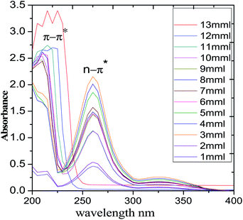 |
| | Fig. 1 UV-visible spectrum of polyaniline functionalized fish-scale graphitic carbon. | |
3.2. FTIR spectroscopy
The FTIR spectra of the FSC and PFFSC are presented in Fig. 2. For the FSC the vibration peak appearing at 1026 cm−1 is related with the P–O bond symmetric vibration. The peak appearing at 1654 cm−1 is associated with amide stretching frequency. Whereas, the PFFSC stretching frequencies are similar to the previous reports31 the peak appearing at 515 cm−1 is associated with the C–N–C bonds in the aromatic benzenoid ring. The peaks shown at 750 cm−1 are associated with the stretching mode of the C–C and C–H bonds, respectively, in the benzenoid ring.32 Further, peak appearing at 1310 cm−1 is associated with the C–N stretching frequency of quinoid and benzenoid ring. The peaks shown at 1511 cm−1 are related with the C![[double bond, length as m-dash]](https://www.rsc.org/images/entities/char_e001.gif) N stretching of quinoid ring. The peak appearing at 3300 cm−1 is associated with the secondary amine N–H stretching frequency. The spectroscopy results confirmed functional groups present in carbon matrix.
N stretching of quinoid ring. The peak appearing at 3300 cm−1 is associated with the secondary amine N–H stretching frequency. The spectroscopy results confirmed functional groups present in carbon matrix.
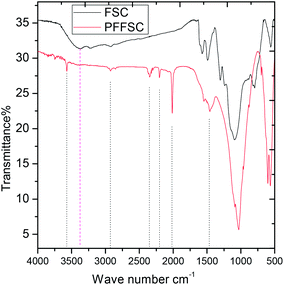 |
| | Fig. 2 The FTIR spectrum of polyaniline functionalized fish-scale graphitic carbon and fish scale graphitic carbon. | |
3.3. Raman spectroscopy
The Raman spectra of FSC and PFFSC are shown in Fig. 3. The peak at 1250 cm−1 is associated with the D band of FSC and PFFSC vibration from the edge of the graphitic carbon matrix.33,34 further, the peak appearing at 1530 cm−1 is associated with the G band sp2 carbon vibration of PFFSC and FSC. The broad peak appearing around 2600 cm−1 is associated to the 2D graphitic carbon peak. Further, new peak appearing at 1168 cm−1 is related to the polyaniline C–H bending vibration of quinoid rings. The Raman images of FSC and PFFSC at different region of porous carbon are shown in Fig. S3(a and b).† From Fig. S3a† the FSC carbon thin sheet showed low intensity due to the absence of polyaniline emeraldine conducting salt, and polyaniline characteristic peaks are not present in the graphitic carbon. And from Fig. S3b† polyaniline functionalized fish scale carbon sheet is shining due to the polyaniline imine salt cross linked over the carbon matrix. The polyaniline functionalized graphitic carbon ID/IG ratio before functionalization was 0.10416, after functionalization graphitic carbon ID/IG ratio is increased up to 1.0303, it indicates that polyaniline has π–π interactions with porous carbon matrix.
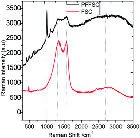 |
| | Fig. 3 Raman spectrum of polyaniline functionalized porous carbon spectrum. | |
3.4. Solid state NMR
The NMR spectra of functionalized polyaniline porous carbon are shown in Fig. 4. Small peaks that appear at 110 ppm, 130 ppm, and 120 ppm show coherence with the literature.35,36 The small peak at 130.1 ppm suggested the presence of imine nitrogen compounds. However, the peak at 93.10 ppm indicates six-membered ring nitrogen compounds. The peak at 158 ppm indicates that quinoid ring formed. The peak that appears at 107 ppm indicates amine groups. On the other hand, the peaks at 123.5 ppm and 113.5 ppm are due to the nitrogen in five membered ring nitrogen.
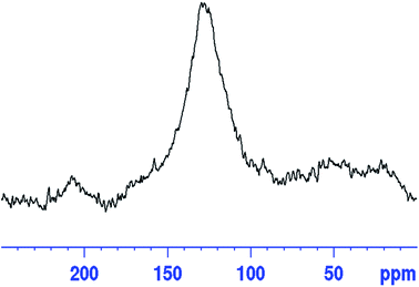 |
| | Fig. 4 Solid state NMR of polyaniline functionalized fish scale graphitic carbon. | |
3.5. XRD
As shown in Fig. 5, the PFFSC is polycrystalline carbon. The peak at 2θ = 10° indicates the 002 plane of graphitic carbon.37 The peak at 2θ = 30° is related to polyaniline characteristic peak incorporated in the fish scale carbon matrix.
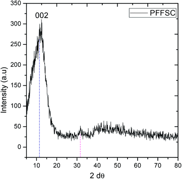 |
| | Fig. 5 XRD spectrum of polyaniline functionalized fish scale graphitic carbon. | |
3.6. Thermogravimetry analysis
The PFFSC weight loss thermogravimetry analysis (TGA) results are shown in Fig. 6A. It can be seen that PFFSC weight loss was initiated at 150 °C due to the loss of water content of PFFSC. The second weight loss was initiated from 200 °C to 600 °C, it revealed that decomposition of organic constituent of PFFSC occurred.38 The weight loss was attributed to the polyaniline polymer polaron chain deformation. Hence, the high temperature decomposition revealed that PFFSC is excellent high temperature coating material. The PFFSC DSC thermal decomposition results are shown in Fig. 6B, the weight loss was initiated at 100 °C, it indicates that water was lost. Further weight loss gradually increased from the 225 °C to 350 °C, due to the fact that the polyaniline emeraldine salt and organic moiety initiated to deform molecular structure. Thus, PFFSC is suitable for high temperature coating materials.
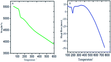 |
| | Fig. 6 Thermogravimetric analysis of polyaniline functionalized fish-scale graphitic carbon: TGA (A) and DSC (B). | |
3.7. Electrochemical stability
Cyclic voltammogram (CV) was performed at constant scan rate 5 mV s−1 at 5 cycles, and 1 M H2SO4 was used as an electrolyte at room temperature as shown in Fig. 7. The PFFSC porous carbon oxidation peak appears from 0.4 mV to 0.2 mV and reduction peak appears from 0.5 mV to 0.9 mV because of change in redox behaviour of PFFSC. Thus, the polyaniline tertiary nitrogen nonbonding electrons delocalization plays a key role for stability of PFFSC.39 Furthermore redox stability of PFFSC was associated with the presence of free electrons of polyaniline polaron chain on PFFSC graphitic carbon. Hence, polyaniline benzenoid and quinoid ring electrons lead to the increased electrochemical stability. For PFFSC the current was increased from 0.1 mA to 0.5 mA, which indicates that polyaniline π-electrons are delocalized on polyaniline chain. Thus, CV studies revealed that polyaniline functionalized porous carbon is electrochemically stable in acidic medium.
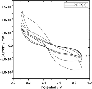 |
| | Fig. 7 Electrochemical stability of polyaniline functionalized fish-scale graphitic carbon. | |
3.8. Microstructure analysis
The microstructure of PFFSC is presented in Fig. 8. The FESEM image of PFFSC (Fig. 8A and B) reveals that the porous carbon pores sizes are around 200 nm, because of FSC graphitic carbon temperature treatment in oxygen atmosphere, and green gas evolution from graphitic carbon matrix. From the TEM image (Fig. 8C and F) of PFFSC porous carbon sheet thickness is around 100 nm, which indicates that mesoporous and macro porous pores are present on graphitic carbon surface.40,41 From the results shown in Fig. 8F we believe that PFFSC has polycrystalline structure judging from the single diffraction pattern index of it. We have also studied porous carbon thickness by using Gatan digital microscopy software. The pore sizes are presented in Fig. 9A and B, it was observed that pores have deep blue colour. In Fig. 9C the TEM image of PFFSC is given, and pores are regularly present in the carbon matrix indicated by dark red colour due to uniform exfoliation of graphitic carbon layer. In Fig. 9D carbon sheet size of PFFSC carbon shows that maximum sheet size is 400 nm because of continuous sonication for 2 h of FSC carbon. As shown in Fig. S4a,† elemental mapping of PFFSC reveals that polyaniline is uniformly functionalized on porous carbon surface. In Fig. S4b† showing the EDX results of PFFSC it was observed that polyaniline imine nitrogen π-electrons interacted with FSC graphitic carbon and percentage of elements indicates that polyaniline covalently interacted with FSC graphitic carbon matrix. The microscopy results revealed good agreements with spectroscopy method.
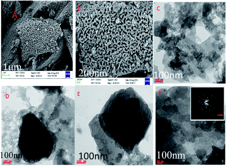 |
| | Fig. 8 Polyaniline functionalized fish-scale carbon: FESEM (A and B), and TEM (C–F) energy dispersion spectroscopy. | |
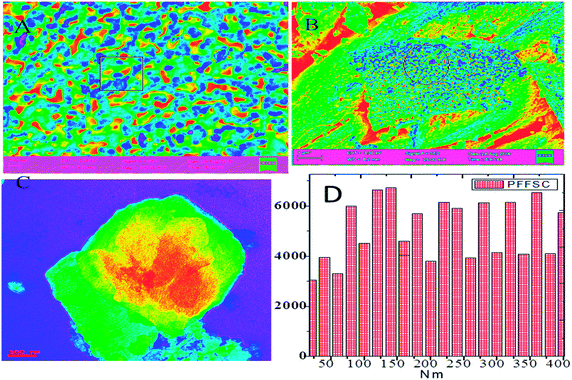 |
| | Fig. 9 FESEM microstructure of polyaniline functionalized fish-scale carbon (A and B) and TEM microstructure of polyaniline functionalized fish scale carbon, (C) is average size of porous carbon sheet (D). | |
3.8.1. Proposed mechanism of polyaniline functionalization. When graphitic fish-scale carbon is heated at 250 °C in O2 atmosphere,42,43 charged oxygen species on carbon surface are formed as shown in Fig. 10.
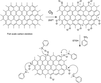 |
| | Fig. 10 Proposed mechanism of polyaniline covalent interaction with fish-scale graphitic carbon. | |
Hence, the polyaniline imine form is chemisorbed on graphitic carbon positive charged oxygen to form corresponding polyaniline covalent bond with fish-scale carbon. Further, the aniline monomer covalently interacts with graphitic carbon. The DFT results are presented in Fig. 11. The model results suggested that energies of frontier molecular orbitals, electrophilicity and hardness values are increased with the number of aniline monomer units due to the active aniline monomer covalently interacting with graphitic surface. Further, the dipole moments were also increased which indicates polyaniline electrostatic interaction with FSC graphitic carbon. Further, the chemical hardness and softness values were increased as well due to the aniline monomer chelated with graphitic carbon nonbonding electrons. The quantum chemical values are presented in Table S1.† We strongly believe that polyaniline interacts via π–π electrons to the graphitic carbon surface.
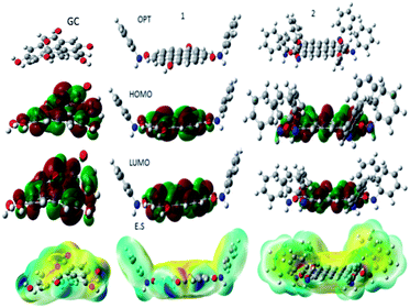 |
| | Fig. 11 Calculations results for the aniline monomer functionalized with graphitic carbon. | |
3.8.2. Coating thickness. The nickel alloys were coated with PFFSC and epoxy as a corrosion inhibition barrier layer in acidic medium as shown in Fig. 12. The epoxy coated nickel alloy thickness is 840.046 Å and PFFSC coated alloy thickness is 881.583 Å for 1 M HCl solution immersion. It was observed that brush coating is uniformly deposited on the nickel alloys. In another case, epoxy coated nickel alloy thickness value was shown to be 807.251 Å and PFFSC coated nickel alloy thickness value was shown to be 842.044 Å for 1 M H2SO4 acidic medium immersion. The model fitting values are presented in Table 2. The brush coating layers are almost uniform in both acidic medium immersed nickel alloy surface.
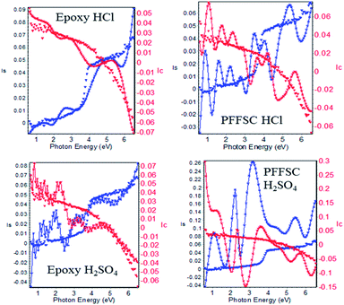 |
| | Fig. 12 Nickel alloy coating thickness for polyaniline functionalized fish-scale carbon and epoxy coatings in both 1 M HCl and 1 M H2SO4 corrosion inhibition studies. | |
3.8.3. Open circuit potential (OCP). The OCP is primary test for corrosion inhibition reaction and it gives direction of inhibition system potential as shown in Fig. 13A and B. The PFFSC and epoxy coated nickel alloys were immersed in 1 M HCl acidic medium as shown in Fig. 13C. The PFFSC coated nickel alloy potential is moving in positive potential direction and epoxy coated nickel alloy potential is moving in negative direction, which is result of aggressive chloride ions diffusion to coated surface. The case of the PFFSC coated nickel alloy immersed in 1 M H2SO4 acid medium is presented in Fig. 13D. The corrosion potential is moving to the corrosion mitigation direction and epoxy coated nickel alloy corrosion potential is moving to negative direction which suggests that epoxy coated nickel alloys initiated oxidation.44 The open circuit potential results suggested that polyaniline functionalized graphitic fish scale carbon has strong physisorption on the alloy surface.
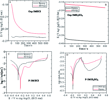 |
| | Fig. 13 Corrosion studies of OCP PFFSC coated and epoxy coated nickel alloys, 1 M HCl (A) and 1 M H2SO4 (B), and the potentiodynamic polarization studies of epoxy coated and PFFSC coated nickel alloy after 5 days immersed in 1 M HCl (C) and 1 M H2SO4 (D) media. | |
3.8.4. Potentiodynamic polarization. The potentiodynamic polarization study was carried out for PFFSC and epoxy coated nickel alloys after 5 days immersed in 1 M HCl and 1 M H2SO4 medium as shown in Fig. 13C. From Fig. 13C it can be seen that for the epoxy coated nickel alloy immersed in 1 M HCl solution corrosion current is increased and corrosion potential is decreased due to the beneath coating oxidation initiated on the alloy surface. The anodic nickel alloy dissolution and cathodic hydrogen evolution increased because epoxy coating failure in acidic environments. Further, in epoxy coated Tafel curve cathodic region hydrogen evolution constantly increased from 0.2 to 0.5 mV due to the failure of epoxy coating. Corrosion inhibition efficiency was extrapolated by Tafel plot cathodic and anodic curves as shown in Fig. S5.† The corrosion inhibition efficiency values are given in Table 1. For the PFFSC coated nickel alloy immersed in 1 M HCl solution corrosion the current value is decreased, and corrosion potential is increased, thus it is observed that the PFFSC acts as corrosion barrier in HCl environments. Further, Tafel curve cathodic region showed that hydrogen evolution occurred at 0.2 mV but not at the extended potentials due to the PFFSC blocking the active surface. As shown in Fig. 13D for the PFFSC coated nickel alloy immersed in 1 M H2SO4 solution the corrosion current density decreased, and corrosion potential increased due to the PFFSC acting as excellent barrier layer on the nickel alloy surface. Furthermore, the Tafel region shows that cathodic hydrogen evolution occurred at 0.2 mV but not continued at other potentials because it was suppressed due to the polyaniline chemisorption on the alloy surface by its nonbonding electrons.45,46 The polyaniline conductive form benezenoid diimine and quinoid diimine free electrons could promote the corrosion inhibition efficiency in acid environment. In another case, epoxy coated nickel alloy immersed in 1 M H2SO4 solution showed the corrosion current increased and corrosion potential decreased due to the epoxy coating break down on alloy surface. The Tafel cathodic hydrogen evolution continues from 0.2 to 0.5 mV due to epoxy coating not being stable in acidic medium. The PFFSC is thus an outstanding coating material in both acidic media. The potentiodynamic polarization results revealed that PFFSC has higher corrosion inhibition in 1 M HCl environment as compared with 1 M H2SO4 medium.
Table 1 Electrochemical corrosion inhibition studies of epoxy coated and polyaniline functionalized fish-scale carbon coated nickel alloys immersed for 5 days in HCl & H2SO4 acids
| Inhibitor |
−Ecorr, m V−1 |
Icorr, m A−1 |
η, % |
Error range |
RCt, Ω (cm−2) |
Cdl, μF (cm−2) |
Error range |
χ2 |
Å |
| Epoxy HCl |
299 |
3.9991 |
|
|
290 |
7.5302 |
0.2555 |
0.7606 |
840.046 |
| PFFSC HCl |
792 |
1.0153 |
74.6186 |
0.8580 |
690 |
5.7667 |
0.2183 |
3.3679 |
881.583 |
| Epoxy H2SO4 |
222 |
6.2924 |
|
|
190 |
4.1884 |
0.1785 |
1.9205 |
807.251 |
| PFFSC H2SO4 |
649 |
2.0597 |
67.2759 |
0.8141 |
400 |
1.0220 |
0.0148 |
0.3601 |
842.044 |
3.8.5. Impedance spectroscopy. Impedance spectroscopy is a sophisticated technique for monitoring the inhibitor molecules corrosion inhibition efficiency. As shown in Fig. 14A–C, for the nickel alloys coated with epoxy and PFFSC immersed in 1 M HCl environment, for the epoxy coated nickel alloy the Nyquist plot semicircle was depressed due to the nickel alloy initiated localized corrosion. Hence the RCt charge transfer values are decreased, and double layer capacitance value is increased up to 7.5302 μF due to nickel alloy surface pitting corrosion initiated. Whereas the impedance frequency of epoxy coated nickel alloy is depressed due to the Cl− ions attack on alloy surface. In the impedance phase of epoxy coated nickel alloy phase angle is decreased due to the alloy surface crevice corrosion occurring. On the other hand, for the PFFSC coated nickel alloy the Nyquist spectrum semicircle is increased and RCt values are increased because graphitic carbon functional groups strongly interact with alloy surface. The Cdl double layer capacitance values are decreased to 5.7667 μF due to the PFFSC physisorption on the alloy surface.47 The PFFSC coated nickel alloy phase angle increased and crevice corrosion was retarded due to the PFFSC carbon blocking active sites of the nickel alloy surface. The PFFSC impedance frequency and impedance phase angle increased due to the PFFSC electrostatic interactions on the nickel alloy surface. The PFFSC can be used as a corrosion inhibition barrier coating in 1 M HCl medium. The impedance values are fitted using equivalent circuit as shown in Fig. 15D.
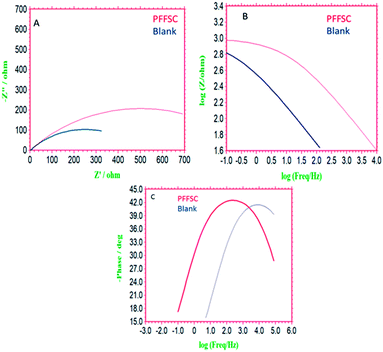 |
| | Fig. 14 Impedance spectrum of epoxy (blank) and polyaniline functionalized fish-scale carbon coated nickel alloy immersed for 5 days in 1 M HCl, Nyquist plot (A), impedance frequency plot (B), impedance phase (C). | |
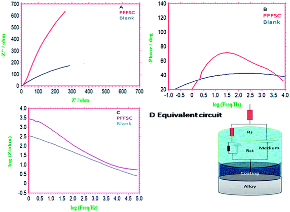 |
| | Fig. 15 Impedance spectrum of epoxy (blank) and polyaniline functionalized fish scale carbon coated nickel alloy immersed 5 days in 1 M HCl, Nyquist plot (A), impedance frequency plot (B), impedance phase (C) and equivalent circuit (D). | |
Further we have investigated the PFFSC corrosion inhibition efficiency in 1 M H2SO4 medium as shown in Fig. 15A–C. For the epoxy coated nickel alloy the semi-circle have been suppressed due to the pitting corrosion initiated on alloy surface. Further, RCt values are decreased and Cdl double layer capacitance values are increased to 4.1884 μF because of epoxy coated nickel alloy undergoing corrosion. Furthermore, impedance phase frequency and impedance frequency are decreased because sulphate ions diffusion increased. In the case of the PFFSC coated nickel alloy semi-circle increased and double layer values decreased to 1.0220 μF due to the PFFSC being strongly physisorbed on the alloy surface by opposite charge. Chemisorption on the alloy surface occurred due to polyaniline non-bonding electrons.48 In the case of the PFFSC.
Coated nickel alloy impedance phase angle and impedance frequency angle are increased due to the SO42− ions diffusion controlled. The polyaniline polaron chain free electrons also contributed to control the SO42− ions diffusion. The polyaniline conducting salt could improve the electron donation to the metal surface due to the alloy dissolution controlled in acidic environments. The polyaniline functionalized fish scale carbon corrosion inhibition barrier is showed to be higher in HCl rather than in H2SO4 medium.
3.8.6. Nickel alloys surface analysis. The PFFSC and epoxy coated nickel alloys after 5 days immersed in 1 M HCl and 1 M H2SO4 medium surface morphology as shown in Fig. 16 and 17(A–F).
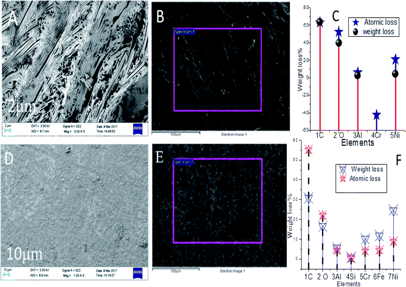 |
| | Fig. 16 Nickel alloy after corrosion studies surface morphology of epoxy (A and B blank), and (C) elements composition weight loss, polyaniline functionalized fish scale carbon (PFFSC) coated nickel alloy immersed 5 days in 1 HCl medium (D)–(F) is elements composition weight loss. | |
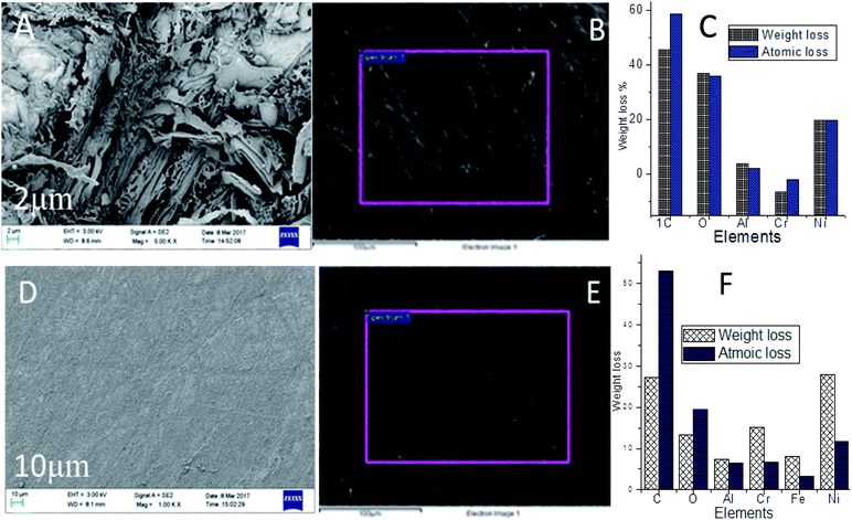 |
| | Fig. 17 (A), (B) and (C ) elements composition weight loss, nickel alloy after corrosion studies surface morphology of epoxy and ((D), (E), and (F) elements composition weight loss PFFSC) polyaniline functionalized fish scale carbon coated nickel alloy immersed 5 days in 1 M H2SO4 medium. | |
Hence, the localised corrosion was controlled by the polyaniline free electrons chemisorbed on the alloy surface. PFFSC non-bonding electrons are transferred to the positively charged nickel alloy surface. In Fig. 16A–C for the epoxy coated nickel alloy immersed in 1 M HCl solution it can be seen that localised corrosion occurs on the surface, because corrosive chloride Cl− ions attack and cause delamination of epoxy coating. In Fig. 16C indicates that nickel alloy weight loss. However, in Fig. 16D–F PFFSC coated nickel alloy showed smooth surface there is no pitting corrosion initiated due to the presence of strong adsorption carbon composite materials. Hence, the nickel alloy was dissolved in the corrosion medium. Whereas, in Fig. 17A–C the results for the epoxy coated nickel alloy immersed in 1 M H2SO4 are given, they show the microstructure being severely affected by localised corrosion due to SO42− ions penetration to epoxy coating. Further in Fig. 17C nickel alloy composition is weight loss. Cathodic hydrogen evolution and anodic alloy dissolution were increased due to the poor stability of the epoxy coated nickel alloy in acidic media. As shown in Fig. 17D–F for the PFFSC coated nickel alloy immersed in 1 M H2SO4 solution localised grain boundary and pitting corrosion were controlled due to the PFFSC coating being strongly adsorbed on active sites of the alloy surface.49,50 Furthermore, the PFFSC porous carbon nonbonding electrons could improve the chemisorption and physisorption on the alloy surface. The nickel alloy microstructure results indicate that polyaniline functionalized porous carbon is an excellent adsorbent on the active alloy surface, and it prevents metal alloys dissolution in acidic media.
3.8.7. Nickel alloy surface ATR-FTIR method analysis. In Fig. S6† the results for the adsorption functional groups obtained by the ATR-FTIR methods analysis for the PFFSC and epoxy coated nickel alloys after five days immersed in both acidic media are given. For the PFFSC coated nickel alloy in both acidic media stretching frequency appearing at 3600 cm−1 is associated with the Ni–O layer formed on the alloy surface.51 The peak appearing at 3000 cm−1 was ascribed to polyaniline protonated imine chemisorbed on the surface. The stretching frequency appearing at 1600 cm−1 was associated with polyaniline N–H groups chemisorbed on nickel alloy surface. However, the nickel surface has different oxidation states, Ni+, Ni2+, which could be driving force to polyaniline imine form physisorbed on the alloy surface. Furthermore, strong peak appearing at 2200 cm−1 was associated with aromatic polyaniline chain free electrons leading to the electrostatic interactions with the alloy surface. The stretching frequency appearing around 1000 cm−1 is related with polyaniline benzenoid free electrons chemisorbed on the nickel alloy surface. The epoxy coated nickel alloy after five days immersed in both acidic media showed weak stretching frequency, the peak appearing at 2000 cm−1 which is associated with the Ni–OH band vibration. As early studies nickel alloy corrosion resistance is investigated at 700 °C temperatures, the report is chromium scale formed it may cause environment.52 the Alloy 690, inhibition efficiency showed that the addition of Zn ions improves corrosion resistance at high pressure water environments.53 However, the both corrosion studies showed that long-time inhibition, it may be caused long time inhibition efficiency due to zinc ions settling down and chromium scale may cause environment pollution. In our work green anticorrosion coating can have prolonged inhibition. The surface adsorption studies suggested that the PFFSC has improved adsorption on the alloy surface.
3.8.8. Quantum chemical calculations. The quantum chemical studies revealed possibility of electron transfer from inhibitor molecules to the metal alloy surface. Polyaniline fragment frontier molecular orbitals are presented in Fig. 18.
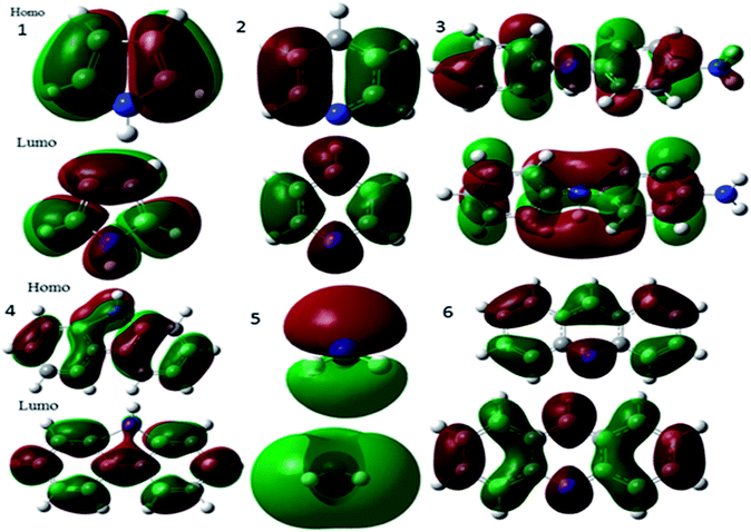 |
| | Fig. 18 HOMO and LUMO frontier molecular orbitals of polyaniline fragments. | |
According to the literature,54 polyaniline major fragments such as benzenoid-diamine, quinoid-diamine, pyridine, pyrrole, and tertiary nitrogen play a significant role to improve the adsorption on alloys surface. However, calculated energy of the HOMO of the polyaniline is directly related to electron donation to metal vacant d orbitals, while the LUMO is related to accepting electrons.55 Hence, the HOMO and LUMO energies of polyaniline fragments are favourable to accept and donate electrons to metal surface. This indicates that inhibitor molecules electron transfer could be possible between the inhibitor molecules and metal empty d orbitals. Further, the quantum chemical studies showed that inhibitor molecules softness value increases, and hardness value decreases, which leads to enhanced inhibitor molecules chemical reactivity. In our case polyaniline fragmentation global softness value is increased and hardness values are decreased as shown in Table 2. The theoretical values have been attributed to the polyaniline functionalized porous carbon being adsorbed on the nickel surface. Whereas, the polyaniline fragments HOMO–LUMO band gap values are also close to each other. This indicates that inhibitor molecules interact with the nickel surface by chemisorption. In addition, the electrophilicity (ω) value increased, thus electron transfer between vacant nickel d orbitals and composite molecules can be possible. Further, the dipole moment value also contributes to corrosion inhibition efficiency of inhibitor molecules, higher dipole movement (DM) values lead to higher inhibition efficiency. As shown in Fig. S7a,† the polyaniline fragment contour structure is distributed uniformly on donor and acceptor of polyaniline fragments molecules, which could improve electron transfer between metal surface and barrier layer. In view of the total electron density values (ΔET) being less than zero, which is attributed to the electron back donation to the inhibitor molecule, this proves that there is electron transfer from inhibitor molecules to alloy surface. The red colour indicates negative charge of inhibitor molecules, and blue colour indicates positive charge of inhibitor molecules. Further, the negative charge of polyaniline functionalized fish carbon could interact with positively charged nickel alloy surface. The theoretical data are coherent with electrochemical results.
Table 2 Quantum chemicals results of polyaniline fragments
| S. no. |
Fragments |
HOMO eV |
LUMO eV |
ΔE eV |
χ eV |
η eV |
σ eV |
ω |
ΔE |
Dm (debye) |
| 1 |
Pyrrole |
5.4101 |
1.1940 |
4.2160 |
3.3020 |
2.1080 |
0.2372 |
2.5861 |
0.5270 |
1.8375 |
| 2 |
Pyridine |
6.8730 |
0.6117 |
6.2613 |
3.7423 |
3.1306 |
0.1597 |
2.2367 |
0.9355 |
2.1922 |
| 3 |
Benzoid |
4.6490 |
0.5251 |
4.1238 |
2.5871 |
2.0619 |
0.2424 |
1.6230 |
0.5154 |
2.0124 |
| 4 |
Carbozole |
5.4425 |
0.6440 |
4.7985 |
3.0432 |
2.3992 |
0.2084 |
1.9300 |
0.5998 |
1.6580 |
| 5 |
Tertiary –N– |
6.8695 |
2.1385 |
4.7309 |
4.5040 |
2.3654 |
0.2113 |
4.2280 |
0.5913 |
1.9129 |
| 6 |
Acridine |
0.5682 |
1.9807 |
3.7021 |
3.8317 |
1.8510 |
0.27012 |
3.96588 |
0.4627 |
1.8632 |
3.8.9. Corrosion mechanism. The PFFSC interaction with the nickel alloy surface is presented in Fig. 19. The PFFSC carbons have heterocyclic fragment free electrons, which could improve the chemisorption. And quantum chemical frontier molecular orbital values supported for electron donation and acceptance from positively charge alloy surface. The polyaniline benzenoid diamines, quinoid diamine, pyridine, and tertiary nitrogen non-bonding electrons lead to the chemisorption on the alloy surface.56,57
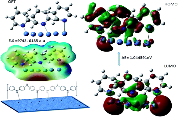 |
| | Fig. 19 Polyaniline adsorption on (111) nickel alloy surface. | |
Hence, the polyaniline fragment ΔE 1.0445 eV values are decreased and electrostatic potential 9743.6185 a.u values is increased indicates that polyaniline adsorbed on nickel alloy surface. In addition, positive charge of polyaniline nitrogen atom can improve the physisorption on the alloy surface to control the hydrogen evolution. However, microscopy and spectroscopy results suggested that polyaniline functionalized porous carbons acts as an excellent adsorbent on alloy surface in acidic media.
4. Conclusions
The efficiency of nickel alloy corrosion inhibition by the polyaniline functionalized fish-scale porous carbon, the highly conductive polymer, is studied in acidic conditions. The theoretical and experimental result leads to the following conclusions. The spectroscopic results revealed that polyaniline covalently functionalized the graphitic carbon matrix and respective functional groups were confirmed. The X-ray crystallographic studies revealed the presence of graphitic carbon polycrystalline structures. The graphitic carbon ID and IG percentage ratio confirmed the polyaniline functionalization of the graphitic carbon surface, and polyaniline characteristic peak was shown to appear. The thermo gravimetric results showed that the PFFSC coating can withstand temperatures up to 200 °C. FESEM and TEM microstructure studies indicate that PFFSC is a porous carbon matrix and is polycrystalline carbon sheet. Electrochemical studies indicate that PFFSC acts as strong barrier layer in acidic environments and it showed inhibition efficiency higher in 1 M HCl medium as compared with 1 M H2SO4. The DFT studies reveal aniline monomer covalent interactions with porous carbon surface. Thus, the PFFSC acts as corrosion resistive barrier in acidic environments.
Conflicts of interest
There are no conflicts to declare.
Acknowledgements
N. P. would like to thank Central University of Gujarat Central Instrument Facility and Non – NET fellowship. The author is thankful to Prof. M. V. Rajasekharan support to completion of research work and UGC Network Resource Centre School of Chemistry Hyderabad of University.
References
- N. Mary, C. Alemany-Dumont, B. Normand, O. Heintz, V. Broudic and C. Jegou, Electrochemical behaviour of copper–nickel alloys as immobilisation matrices for the storage of fission products in CO2-enriched synthetic groundwater, Electrochim. Acta, 2013, 98, 11–19 CrossRef CAS.
- G. M. A. Waheed and A. Badawy, The use of cysteine, N-acetyl cysteine and methionine as environmentally friendly corrosion inhibitors for Cu–10Al–5Ni alloy in neutral chloride solutions, Electrochim. Acta, 2013, 108, 860–866 CrossRef.
- F. Meng, E. Hou Han, J. Wang, Z. Zhang and W. Ke, Localized corrosion behavior of scratches on nickel-base Alloy 690TT, Electrochim. Acta, 2011, 56, 1781–1785 CrossRef CAS.
- G. Kear, B. D. Barker, K. R. Stokes and F. C. Walsh, Electrochemistry of non-aged 90–10 copper–nickel alloy (UNS C70610) as a function of fluid flow part 2: cyclic voltammetry and characterisation of the corrosion mechanism, Electrochim. Acta, 2007, 52, 2343–2351 CrossRef CAS.
- G. Qiu, A. Zhu and C. Zhang, Hierarchically structured carbon nanotube–polyaniline nano brushes for corrosion protection over a wide pH range, RSC Adv., 2017, 7, 35330–35339 RSC.
- M. Kashifa and S. Ahmad, Polyorthotoluidine dispersed castor oil polyurethane anticorrosive nanocomposite coatings, RSC Adv., 2014, 4, 20984–20999 RSC.
- C. Oueiny, S. Berlioz and F. X. Perrin, Assembly of polyaniline nanotubes by interfacial polymerization for corrosion protection, Phys. Chem. Chem. Phys., 2016, 18, 3504–3509 RSC.
- H. Gomez, M. K. Ram, F. Alvi, E. Stefanakos and A. Kumar, Novel Synthesis, Characterization, and Corrosion Inhibition Properties of Nanodiamond-Polyaniline Films, J. Phys. Chem. C, 2010, 114, 18797–18804 CrossRef CAS.
- J. A. Syed, S. Tang, H. Lu and X. Meng, Water-Soluble Polyaniline–Polyacrylic Acid Composites as Efficient Corrosion Inhibitors for 316SS, Ind. Eng. Chem. Res., 2015, 54, 2950–2959 CrossRef CAS.
- F. Chen and P. Liu, Conducting Polyaniline Nanoparticles and their Dispersion for Waterborne Corrosion Protection Coatings, ACS Appl. Mater. Interfaces, 2011, 3, 2694–2702 CrossRef CAS PubMed.
- X. Sheng, W. Cai, L. Zhong, D. Xie and X. Zhang, Synthesis of Functionalized Graphene/Polyaniline Nanocomposites with Effective Synergistic Reinforcement on Anticorrosion, Ind. Eng. Chem. Res., 2016, 55, 8576–8585 CrossRef CAS.
- H. Lu, S. Zhang, W. Li, Y. Cui and T. Yang, Synthesis of Graphene Oxide-Based Sulfonated Oligoanilines Coatings for Synergistically Enhanced Corrosion Protection in 3.5% NaCl Solution, ACS Appl. Mater. Interfaces, 2017, 9, 4034–4043 CrossRef CAS PubMed.
- L. Lv, S. Yuan, Y. Zheng, B. Liang and S. O. Pehkonen, Surface Modification of Mild Steel with Thermally Cured Antibacterial Poly(vinylbenzyl chloride)–Polyaniline Bilayers for Effective Protection against Sulfate Reducing Bacteria Induced Corrosion, Ind. Eng. Chem. Res., 2014, 53, 12363–12378 CrossRef CAS.
- B. Ramezanzadeh, P. Kardar, G. Bahlakeh, Y. Hayatghei and M. Mahdavian, Fabrication of a Highly Tunable Graphene Oxide Composite through Layer-by-Layer Assembly of Highly Crystalline Polyaniline Nanofibers and Green Corrosion Inhibitors: Complementary Experimental and First-Principles Quantum-Mechanics Modelling Approaches, J. Phys. Chem. C, 2017, 121, 20433–20450 CrossRef CAS.
- H. Khatoon and S. Ahmad, Accurate Adsorption Thermodynamics of Small Alkanes in Zeolites. Ab initio Theory and Experiment for H-Chabazite, ACS Appl. Mater. Interfaces, 2019, 11, 2374–2385 CrossRef CAS PubMed.
- L. T. Sein, Y. Wei and S. A. Jansen, Halogen-Capped Aniline Trimers. Away from the Polyaniline Paradigm by Isosteric Replacement of Amino Groups: A Theoretical Study, J. Phys. Chem. A, 2000, 104, 11371–11374 CrossRef CAS.
- B. Ramezanzadeh, G. Bahlakeh and M. Ramezanzadeh, Polyaniline-cerium oxide (PAni-CeO2) coated graphene oxide for enhancement of epoxy coating corrosion protection performance on mild steel, Corros. Sci., 2018, 137, 111–126 CrossRef CAS.
- Y. Hayatghei, B. Ramezanzadeh, P. Kardar and M. A. Mahdavian, Comparative study on fabrication of a highly effective corrosion protective system based on graphene oxide-polyaniline nanofibers/epoxy composite, Corros. Sci., 2018, 133, 358–373 CrossRef.
- I. B. Polovo, A. V. Abramov, A. F. Gibadullina, R. R. Alimgulov, V. V. Karpov, A. Y. Zhilyakov, V. A. Khotinov and S. V. Belikov, The effect of microstructure on the corrosion resistance of VDM® alloy C-4 in molten salts, J. Alloys Compd., 2019, 810, 15175 Search PubMed.
- E. Hamed, S. S. A. E. Rehim, M. F. E. Shahat and A. M. Shaltot, Corrosion inhibition of nickel in H2SO4 Solution by alanine, Mater. Sci. Eng., B, 2012, 177, 441–448 CrossRef CAS.
- J. Fang, K. Xu, L. Zhu, Z. Zhou and H. Tang, A study on mechanism of corrosion protection of polyaniline coating and its failure, Corros. Sci., 2007, 49, 4232–4242 CrossRef CAS.
- M. Sababi, J. Pan, E. P. Augustsson, E. Sundell and P. Claessona, Influence of polyaniline and ceria nanoparticle additives on corrosion protection of a UV-cure coating on carbon steel, Corros. Sci., 2014, 84, 189–197 CrossRef CAS.
- F. Xiao, C. Qian, M. Guo, J. Wang, X. Yan, H. Li and L. Yue, Anticorrosive durability of zinc-based waterborne coatings enhanced by highly dispersed and conductive polyaniline/graphene oxide composite, Prog. Org. Coat., 2018, 125, 79–88 CrossRef CAS.
- E. Akbarinezhad, M. Ebrahimi and H. R. Faridi, Corrosion inhibition of steel in sodium chloride solution by undoped polyaniline epoxy blend coating, Prog. Org. Coat., 2009, 64, 361–364 CrossRef CAS.
- J. Wang, L. Shen, Y. Xu, H. Dou and X. Zhang, Lamellar-structured biomass-derived phosphorus and nitrogen-co-doped porous carbon for high-performance supercapacitors, New J. Chem., 2015, 39, 9497–9503 RSC.
- B. Huang, H. Shao, N. Liu, Z. J. Xu and Y. Huang, From fish scales to highly porous N-doped carbon a low cost material solution for CO2 capture, RSC Adv., 2015, 5, 88171–88175 RSC.
- S. Zhao, C. Li, W. Wang, H. Zhang, M. Gao, X. Xiong, A. Wang, K. Yuan, Y. Huang and F. Wang, A novel porous nanocomposite of sulfur/carbon obtained from fish scales for lithium–sulfur batteries, J. Mater. Chem. A, 2013, 1, 3334–3339 RSC.
- Y. Zhang, Z. Gao, X. Yang, J. Chang, Z. Liu and K. Jiang, Fish-scale-derived carbon dots as efficient fluorescent nanoprobes for detection of ferric ions, RSC Adv., 2019, 9, 940–949 RSC.
- L. Pan, L. Pu, Y. Shi, S. Song, Z. Xu, R. Zhang and Y. Zheng, Synthesis of Polyaniline Nanotubes with a Reactive Template of Manganese Oxide, Adv. Mater., 2007, 19, 461–464 CrossRef CAS.
- G. Yang, W. Hou, X. Feng, L. Xu, Y. Liu, G. Wang and W. Ding, Nanocomposites of polyaniline and a layered inorganic acid host: polymerization of aniline in the layers, conformation, and electrochemical studies, Adv. Funct. Mater., 2007, 17, 401–412 CrossRef CAS.
- M. Xue, F. Li, J. Zhu, H. Song, M. Zhang and T. Cao, Structure-Based Enhanced Capacitance: In Situ Growth of Highly Ordered Polyaniline Nanorods on Reduced Graphene Oxide Patterns, Adv. Funct. Mater., 2012, 22, 1284–1290 CrossRef CAS.
- S. Dhibar, P. Bhattacharya, G. Hatui, S. Sahoo and C. K. Das, Transition Metal-Doped Polyaniline/Single-Walled Carbon Nanotubes Nanocomposites: Efficient Electrode Material for High Performance Supercapacitors, ACS Sustainable Chem. Eng., 2014, 2, 1114–1127 CrossRef CAS.
- J. W. Kim, E. J. Siochi, J. C. Nunez, K. E. Wise, J. W. Connell and Y.
R. A. L. Wincheski, Polyaniline Carbon Nanotube Sheet Nanocomposites Fabrication and Characterization, ACS Appl. Mater. Interfaces, 2013, 5, 8597–8606 CrossRef CAS PubMed.
- J. Chen, B. Guo, T. W. Eyster and P. X. Ma, Super stretchable electroactive elastomer formation driven by aniline trimer self-assembly, Chem. Mater., 2015, 27, 5668–5677 CrossRef CAS PubMed.
- P. Anilkumar and M. Jayakannan, Self-Assembled Cylindrical and Vesicular Molecular Templates for Polyaniline Nanofibers and Nanotapes, J. Phys. Chem. B, 2009, 113(34), 11614–11624 CrossRef CAS PubMed.
- K. Shigeki, H. Yo and Y. Chiharu, A solid-state NMR study of the carbonization of polyaniline, Carbon, 2013, 55, 160–167 CrossRef.
- T. S. Miller, A. Belen Jorge, M. Tsuter, A. Sella, F. Cora and P. F. McMilla, Carbon nitrides: synthesis and characterization of a new class of functional materials, Phys. Chem. Chem. Phys., 2017, 19, 15613–15638 RSC.
- J. W. Jeon, S. R. Kwon, F. Li and J. L. Lutkenhaus, Spray-on Polyaniline/Poly(acrylic acid) Electrodes with Enhanced Electrochemical Stability, ACS Appl. Mater. Interfaces, 2015, 7, 24150–24158 CrossRef CAS PubMed.
- I. Kovalenko, D. G. Bucknall and G. Yushin, Detonation Nanodiamond and Onion-Like-Carbon-Embedded Polyaniline for Supercapacitors, Adv. Funct. Mater., 2010, 20, 3979–3986 CrossRef CAS.
- Z. Niu, Z. Yang, Z. Hu, Y. Lu and C. C. Han, Polyaniline–Silica Composite Conductive Capsules and Hollow Spheres, Adv. Funct. Mater., 2003, 13, 949–954 CrossRef CAS.
- V. Selvamani, R. Ravikumar, V. Suryanarayanan, D. Velayuthama and S. Gopukumar, Fish scale derived nitrogen doped hierarchical porous carbon-a high rate performing anode for lithium ion cell, Electrochim. Acta, 2015, 182, 1–10 CrossRef CAS.
- M. Periasamy, M. Shanmugaraja, P. O. Reddy, M. Ramusagar and G. A. Rao, Synthetic Transformations Using Molecular Oxygen-Doped Carbon Materials, J. Org. Chem., 2017, 82, 4944–4948 CrossRef CAS PubMed.
- A. M. Masillamani, N. Perinka, M. Hajna, J. Stejskal, D. Tondelier, Y. Bonnassieux, J. C. Vanel, B. Geffroy and D. Mencaraglia, Charge transport and contact resistance in coplanar devices based on colloidal polyaniline dispersion, J. Polym. Sci., Part B: Polym. Phys., 2016, 54, 1710–1716 CrossRef CAS.
- B. Baytekin, H. T. Baytekin and B. A. Grzybowski, Mechanically Driven Activation of Polyaniline into its Conductive Form, Angew. Chem., Int. Ed., 2014, 53, 6946–6950 CrossRef CAS PubMed.
- L. Lv, S. Yuan, Y. Zheng, B. Liang and S. O. Pehkonen, Surface Modification of Mild Steel with Thermally Cured Antibacterial Poly(vinylbenzyl chloride)–Polyaniline Bilayers for Effective Protection against Sulfate Reducing Bacteria Induced Corrosion, Ind. Eng. Chem. Res., 2014, 53, 12363–12378 CrossRef CAS.
- Z. Feng, M. An, L. Ren, J. Zhang, P. Yanga and Z. Chen, Corrosion mechanism of nanocrystalline Zn–Ni alloys obtained from a new DMH-based bath as a replacement for Zn and Cd coatings, RSC Adv., 2016, 6, 64726–64740 RSC.
- L. Elias, K. Udaya Bhat and A. C. Hegde, Development of nanolaminated multilayer Ni–P alloy coatings for better corrosion protection, RSC Adv., 2016, 6, 34005–34013 RSC.
- C. H. Hsu and M. L. Chen, Corrosion behavior of nickel alloyed and austempered ductile irons in 3.5% sodium chloride, Corros. Sci., 2010, 52, 2945–2949 CrossRef CAS.
- Y. Li, X. Fan, N. Tang, H. Bian, Y. Hou, Y. Koizumi and A. Chiba, Effects of partially substituting cobalt for nickel on the corrosion resistance of a Ni–16Cr–15Mo alloy to aqueous hydrofluoric acid, Corros. Sci., 2014, 78, 101–110 CrossRef CAS.
- A. Kitla, O. V. Safonova and K. Fottinger, Infrared Studies on Bimetallic Copper/Nickel Catalysts Supported on Zirconia and Ceria/Zirconia, Catal. Lett., 2013, 143, 517–530 CrossRef CAS PubMed.
- H. Ullah, A. Ali Shah, S. Bilal and K. Ayub, DFT Study of Polyaniline NH3, CO2, and CO Gas Sensors: Comparison with Recent Experimental Data, J. Phys. Chem. C, 2013, 117, 23701–23711 CrossRef CAS.
- Y. Xiea, J. Zhang, D. J. Younga and W. Zheng, Effect of Fe on corrosion of Ni-20Cr and Ni-30Cr alloys in wet CO2 gas at 650 and 700 °C, Corros. Sci., 2019, 154, 129–143 CrossRef.
- R. Rachidi, B. E. Kihel and F. Delaunois, Microstructure and mechanical characterization of NiCrBSi alloy and NiCrBSi-WC composite coatings produced by flame spraying, Mater. Sci. Eng., B, 2019, 241, 13–21 CrossRef CAS.
- D. S. Su and S. G. Perathoner, Centi. Nanocarbons for the Development of Advanced Catalysts, Chem. Rev., 2013, 113, 5782–5816 CrossRef CAS PubMed.
- C. Xing, Z. Zhang, L. Yu and L. Zhang, Electrochemical corrosion behavior of carbon steel coated by polyaniline copolymers micro/nanostructures, RSC Adv., 2014, 4, 32718–32725 RSC.
- F. Yang, T. Liu, J. Li, S. Qiu and S. H. Zhao, Anticorrosive behaviour of a zinc-rich epoxy coating containing sulfonated polyaniline in 3.5% NaCl solution, RSC Adv., 2018, 8, 13237–13247 RSC.
- N. Palaniappan, I. Cole, S. F. Bristol, K. Balasubramaniuan and C. Lal, Praseodymium-decorated graphene oxide as a corrosion inhibitor in acidic media for the magnesium AZ31 alloy, RSC Adv., 2018, 8, 34275–34286 RSC.
Footnote |
| † Electronic supplementary information (ESI) available. See DOI: 10.1039/d0ra00593b |
|
| This journal is © The Royal Society of Chemistry 2020 |
Click here to see how this site uses Cookies. View our privacy policy here.  Open Access Article
 *a,
I. S. Cole
 *b,
K. Damodaranc,
A. Kuznetsov
 d,
K. R. Justin Thomas
 e and
Balasubramanian K.
 f
f
![[double bond, length as m-dash]](https://www.rsc.org/images/entities/char_e001.gif) N–,
N–, ![[double bond, length as m-dash]](https://www.rsc.org/images/entities/char_e001.gif) O heteroatom functionalized fish-scale porous carbon was used for fluorescent moiety for detection of metal ions by Gao et al.28 The results showed lower cytotoxicity as compared with other carbon materials.
O heteroatom functionalized fish-scale porous carbon was used for fluorescent moiety for detection of metal ions by Gao et al.28 The results showed lower cytotoxicity as compared with other carbon materials.


![[double bond, length as m-dash]](https://www.rsc.org/images/entities/char_e001.gif) N stretching of quinoid ring. The peak appearing at 3300 cm−1 is associated with the secondary amine N–H stretching frequency. The spectroscopy results confirmed functional groups present in carbon matrix.
N stretching of quinoid ring. The peak appearing at 3300 cm−1 is associated with the secondary amine N–H stretching frequency. The spectroscopy results confirmed functional groups present in carbon matrix.


