
 Open Access Article
 This Open Access Article is licensed under a Creative Commons Attribution-Non Commercial 3.0 Unported Licence
The influence of the electron transport layer on charge dynamics and trap-state properties in planar perovskite solar cells†
Man Yu *a,
Yanru Guob,
Shuai Yuanb,
Jia-Shang Zhaob,
Yujun Qin*b and
Xi-Cheng Ai*b
*a,
Yanru Guob,
Shuai Yuanb,
Jia-Shang Zhaob,
Yujun Qin*b and
Xi-Cheng Ai*b
aSchool of Materials Engineering, Xi'an Aeronautical University, Xi'an 710077, China. E-mail: yuman@xaau.edu.cn
bDepartment of Chemistry, Renmin University of China, Beijing 100872, P. R. China. E-mail: xcai@ruc.edu.cn
First published on 26th March 2020
Abstract
Despite the outstanding photovoltaic performance of perovskite solar cells, the correlation between the electron transport layer and the mechanism of photoelectric conversion is still not fully understood. In this paper, the relationship between photovoltaic performance and carrier dynamics is systematically studied in both TiO2- and SnO2-based planar perovskite devices. It is found that the different electron transport layers result in distinct forward scan results and charge dynamics. Based on the charge dynamics results, the influence of the electron transport layer on charge carrier transport and charge recombination is revealed. More importantly, the trap-state density is characterized, which is proven to be related to the charge carrier dynamics and the specific hysteresis behaviour in the perovskite solar cells. The present work would provide new insights into the working mechanisms of electron transport layers and their effect on hysteresis.
1. Introduction
Perovskite solar cells (PSCs) have attracted great attention in recent years. The certified efficiency of PSCs has skyrocketed to 25.2%,1 owing to the superb optoelectronic properties of the organic–inorganic hybrid perovskite materials, including high photoabsorption coefficients,2 tunable band gaps,3 high charge mobilities,4 and ambipolar characteristics.5 The photovoltaic performance and device stability of PSCs is improved by optimizing the morphology of each functional layer and device structure, controlling crystallization of perovskites and engineering the interfacial structure. However, the PSCs performance could be further improved before commercialization by improving their environmental stability and electrical hysteresis.A typical PSC consists of a perovskite layer sandwiched between an electron transport layer (ETL) and a hole transport layer (HTL). The outstanding photovoltaic performance of PSCs depends strongly on the property of the ETL in the devices. The ETL plays an important role in achieving high power conversion efficiency (PCE). ETLs not only influence the charge transfer and charge collection, but also behave as the hole blocking layer to suppress the electron–hole recombination at the interface. Hence, ETLs may dictate the open circuit voltage as well as the fill factor of solar cells. In principle, an ideal ETL needs to meet the following criteria:6,7 (i) well aligned energy levels for efficient charge transfer and hole blocking, which reduces open voltage loss and improves electron transport from perovskite to the ETL; (ii) high electron mobility in ETL, which facilitates high efficiency charge extraction from the perovskite films and reduces charge recombination; (iii) high optical transmittance, which reduces the optical energy loss; (iv) high stability, easy processing and low cost, which are essential for the final commercialization of PSCs.
Thus far, TiO2 is the most commonly used electron transport material. However, it requires high temperature sintering to obtain a dense, good quality TiO2 ETL with relatively high crystallinity and conductivity. This high temperature process hinders its application in simple and cost-effective production of solar cells on flexible substrates. Moreover, the electron mobility of TiO2 ETL is too low (0.1–10 cm2 V−1 s−1) to match with that of the perovskite layer (24.81 cm2 V−1 s−1), which limits the electron transport and increases the possibility of charge recombination,8 when a HTL with high hole mobility is used.6,9 Recently, low-temperature prepared stannic oxide (SnO2), regarded as a better alternative ETL, has been investigated.10,11 Ke et al. first demonstrated a regular planar PSC with high PCE and improved hysteresis using SnO2 as the ETL.12 Compared to TiO2, SnO2 exhibits many advantages for PSCs.13,14 SnO2 has 100 times higher electron mobility (up to 240 cm2 V−1 s−1)15 and a deeper conduction band.16,17 Also, with a wide bandgap of ∼4.0 eV, SnO2 absorbs much less UV light, resulting in higher chemical stability than TiO2.
Planar perovskite solar cells based on TiO2 and SnO2 ETLs also exhibit different photovoltaic performances represented in their hysteresis.18–20 Therefore, it is interesting to establish how the ETLs affect the behavior of the hysteresis. Furthermore, the understanding of the correlation between ETLs charge dynamics and photovoltaic performance is still limited.
In this work, TiO2- and SnO2-based planar PSCs are prepared and compared in their photovoltaic performances. Charge carrier transport/recombination dynamics of PSCs from different ETLs are systematically investigated by transient photocurrent and photovoltage measurements. Furthermore, the trap-state properties are explored using time-resolved charge extraction. By taking the dynamics results into account, the influence of ETLs on photovoltaic performances and charge dynamics are comprehensively discussed.
2. Experimental section
2.1 Fabrication of PSCs
Unless otherwise stated, all materials were purchased from Alfa Aesar and used as received. The FTO glass substrates were sequentially coated of compact TiO2 and SnO2 thin films, respectively, followed by depositing of perovskite precursors by the antisolvent method.21,22 The hole transport layer was successively spin-coated after thermal annealing of the perovskite active layer (at 100 °C for 1 h). Finally, 60 nm of Au was thermally evaporated as the counter electrode. The detailed PSCs construction information was included in the ESI.†2.2 Characterization
The morphologies of the perovskite films were characterized by field-emission scanning electron microscopy (FE-SEM, Hitachi SU8010) at an accelerating voltage of 5 kV. X-ray diffraction (XRD) analysis was conducted on a Shimadzu XRD-7000 using Cu-Kα radiation in the 2θ range from 10° to 60° at a scan rate of 2° per min. UV-vis absorption measurements were performed on a Shimadzu UV-3600 spectrometer. The steady-state photoluminescence (PL) spectroscopy measurements (Edinburgh FLS980 spectrometer) were carried out at an excitation wavelength of 510 nm with irradiation from the side of spin-coated materials.The current density (J)–voltage (V) characteristics were obtained by exposing the PSCs to a standardized solar simulator, which was calibrated by a standard silicon reference cell to AM 1.5G illumination (100 mW cm−2). The applied bias voltage was swept from open circuit to short circuit (reverse scan) and backwards (forward scan) at a scan rate of 1 mV s−1 without light soaking or voltage treatment history. A metal aperture mask was used to define the active area to 0.1 cm2, and all data was acquired by a sourcemeter (Keithley 2400).
2.3 Transient photovoltage (TPV) and transient photocurrent (TPC) measurements
TPV and TPC measurements were conducted following previous reports.23,24 The cell was illuminated from the substrate side by a green light-emitting diode (LED) with central wavelength of 530 ± 5 nm to generate different open circuit photovoltages (Vph). The illumination was superimposed with weak laser pulses (532 nm, 7 ns) as the intensity modulation, which creates an open circuit photovoltage modulation, ΔVph. The intensity of the pulsed laser was adjusted by neutral filters so that ΔVph is less than 5% of Vph. By adjusting the intensity of LED, a series of desired Vph were obtained. The results of TPV were recorded by an oscilloscope (64Xs, Lecroy) with 1 MΩ of input impendence, while TPC results were recorded with 50 Ω of input impendence.2.4 Time-resolved charge extraction measurement
The time-resolved charge extraction (TRCE) measurements were conducted as previously reported.25 Briefly, a laser diode (530 nm) was used as the excitation source, and an analogous electric switch with a response time of 10 ns was connected to the PSC device in parallel circuit. Both perovskite devices and the electric switch were controlled by a digital delay and pulse generator (DG535, Stanford Research System). The measurements were taken by switching between open-circuit and short-circuit conditions at different given time. Open circuit represented that 1 MΩ was paralleled with the device, which recorded the photovoltage evolutions. Meanwhile, the short circuit condition means that 50 Ω was paralleled with the device to characterize the charge extraction process. The evolution of the electric signals were recorded by a digital oscilloscope (64Xs, Lecroy).3. Results and discussion
The morphologies of perovskite active layers deposited on TiO2 and SnO2 ETLs are displayed in Fig. 1a and b. Both perovskite films are uniform with good crystal quality, a similar compact texture with grain sizes which are in the range of hundreds of nanometers. The perovskite films with high coverage and quality can effectively absorb and utilize light, which in turn facilitates charge excitation, contributing to the photoelectric conversion and photovoltaic performance.23 It is believed that the nature of substrates could strongly influence the growth of perovskite film.26–28 Obviously, in our case, the grain size of perovskite based SnO2 (∼291 nm) ETL is larger than that on TiO2 (∼247 nm) substrate (shown as inserted histograms in Fig. 1a and b). Detailed statistics of the perovskite grain sizes are shown in Fig. S1.† Larger perovskite grain sizes obtained on the SnO2 ETL suggests that SnO2 is more favorable for the growth of perovskite. Enlarged grains with reduced density of grain boundaries and defects in the perovskite films can effectively improve the device performance.27,29 XRD patterns reveal the phase compositions and crystallinities of the perovskite films on different ETLs. As shown in Fig. 1c and d, both films exhibit the same dominant diffraction peaks from the (110) and (220) planes at around 14.7° and 29.0°,30,31 respectively, which are the characteristic peaks for a tetragonal perovskite. There is no obvious difference in the XRD patterns, suggesting that the crystal structures of the perovskite films are almost identical on TiO2 and SnO2 ETLs. | ||
| Fig. 1 Top-view SEM images of perovskite films on (a) TiO2 and (b) SnO2 substrates, and corresponding XRD patterns of the (c) TiO2-based and (d) SnO2-based samples. The inset in (a) and (b) show the corresponding crystal size distributions. | ||
The UV-vis absorption spectra of perovskite films deposited on quartz, TiO2 and SnO2 are shown in Fig. 2a, respectively. The perovskite films on these three different substrates exhibit nearly identical absorption intensities and profiles from the UV-visible to the near-infrared region with the absorption onset at 780 nm. The steady-state PL measurements were also carried out to investigate the charge transfer kinetics of photogenerated carriers transporting from perovskite films to the TiO2 and SnO2 ETLs. To exclude the thickness effect, the cross-section SEM images of the devices are shown in Fig. S2,† demonstrating that the perovskite films with the same thickness on different substrates. Hence, the steady-state PL intensity (Fig. 2b) represents the probability of charge extraction through the interfaces from the perovskite films to the ETLs. Given the absorption spectra of the perovskite films are independent to the nature of the substrates (Fig. 2a), the lowest PL intensity from the SnO2 ETL suggests a stronger charge extract capability of SnO2 in comparison to TiO2.
 | ||
| Fig. 2 (a) UV-vis absorption and (b) steady-state PL spectra of perovskite films deposited on quartz (black), TiO2 (red) and SnO2 (blue), respectively. | ||
The representative J–V characteristics of the best PSCs based on TiO2 and SnO2 are presented in Fig. 3, and corresponding photovoltaic parameters are summarized in Fig. 3c. It is clear that there are no significant differences short-circuit current (JSC), open-circuit voltage (VOC), fill factor (FF) and PCE between TiO2 and SnO2 based PSCs in the reverse scans. However, the performances in the forward scans are significantly different between TiO2- and SnO2-based PSCs. Due to a much lower performance of TiO2-PSC in the forward scan (Fig. 3a), its hysteresis phenomenon is much more remarkable than that from the SnO2-based PSC (Fig. 3b). The photovoltaic parameters of TiO2-based PSCs (i.e., FF and PCE) obtained from the forward scan are much lower than those obtained from the reverse scan. For detail, as listed in Fig. 3c, SnO2-based device showed a VOC of 1032 mV, a JSC of 20.95 mA cm−2, a FF of 74.88%, and a PCE of 16.22% under reverse scan, which are slightly decreased to 1026 mV, 20.93 mA cm−2, 73.06% and 15.68%, respectively, under forward scan. However, for TiO2-based PSC, all parameters, including VOC, JSC, FF and PCE are decreased in the forward scan. To evaluate the hysteresis quantitatively, we calculated the hysteresis index, defined as (PCEreverse − PCEforward)/PCEreverse.32 SnO2-PSC exhibited the smaller hysteresis index of 3.3%, in contrast to 41.6% for the TiO2-PSC. This observation is in agreement with published literature.13,33
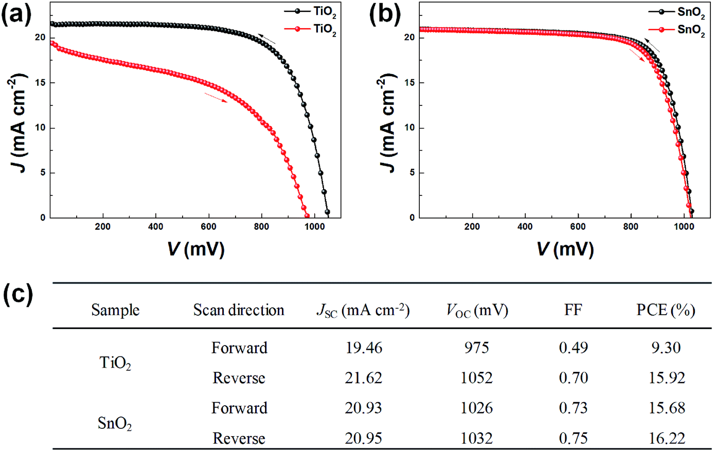 | ||
| Fig. 3 J–V curves obtained from the best device with (a) TiO2- and (b) SnO2-based solar cells, respectively. Black curves are the reverse scan and red curves are the forward scan. (c) Photovoltaic performance of the corresponding solar cells under simulated 1 sun illumination (AM 1.5, 100 mW cm−2). | ||
The observed hysteresis from the PSCs were further confirmed by analyzing large number of PSCs devices based on either TiO2 or SnO2 ETLs prepared to investigate under identical conditions. The statistical results of the photovoltaic parameters of fifteen PSCs, including JSC, VOC, FF and PCE, are shown in Fig. 4. It is clear that the severe hysteresis phenomenon for TiO2-PSC and low hysteresis for SnO2-PSC are highly reproducible. The mechanisms behind the photovoltaic performance and distinct hysteresis of the two types of PSCs will be further explored in depth below.
 | ||
| Fig. 4 The statistical photovoltaic parameters (JSC, VOC, FF, and PCE) under reverse scan and forward scan of TiO2- and SnO2-based planar PSCs. Black squares are the reverse scan results and red solid circles are the forward scan results. | ||
To elucidate the underlying mechanism of charge carrier recombination and transport process in the devices, TPV and TPC measurements were performed. These techniques have been widely employed for exploring the carrier behavior in solar cells.24,34,35 Several TPV and TPC curves extracted from the original results are displayed in Fig. S3.† The photovoltage (Vph) decay traces were fitted with a bi-exponential function, and the apparent recombination time constant τr and transport time constant τt was calculated according to τ = (A1τ1 + A2τ2)/(A1 + A2). Fig. 5 shows the τr and τt as a function of Vph for both TiO2-PSC and SnO2-PSC devices. Overall, charge recombination rates were increased with the increase of Vph. This is due to the accumulation of large number photo-induced carriers at high Vph which accelerates the charge recombination process. For both devices, a pseudo linear correlation between τr and Vph at the semi-logarithmic plot was observed,23,24 which suggests that the carrier recombination follows the trap-limited recombination.36,37 Meanwhile, the τr for the TiO2-PSC is always less than that for the SnO2-PSC over the entire Vph range. This confirms a faster carrier recombination in TiO2-PSC, which is generally detrimental to the photovoltaic performance.
 | ||
| Fig. 5 (a) Vph-dependent charge carrier recombination and (b) charge transport constants derived from the TPV and TPC measurements for TiO2- and SnO2-based planar PSCs respectively. | ||
The dependency of τt on Vph is shown in Fig. 5b, which exhibits a nearly constant value for each of the cells, similar to those in the literatures.23,38,39 Moreover, it was found that the photocurrent decay time constant was significantly reduced from 0.25 μs to 0.11 μs (Fig. 5b), when TiO2 is replaced by SnO2 as the ETL. This indicates a dramatic improvement of charge extraction efficiency by SnO2, which is consistent with the reduced recombination rate and low hysteresis from SnO2, as shown in Fig. 3. In principle, it could be proposed that by passivation of trap-states, the charge recombination is effectively suppressed and the charge transport is significantly improved for the SnO2 ETL, thus the hysteresis of the device is eliminated.
TRCE is an effective technique to evaluate charge distribution within the solar cells. The extracted charge (Q) at different photovoltage was obtained by integrating the extraction current curves vs. decay time (Fig. S4†), shown in Fig. 6. It is clear that the two cells showed similar extracted charge at the low Vph region (≤300 mV). However, by increasing Vph (>300 mV), the Q value of a TiO2-PSC increases more rapidly in comparison to SnO2. In addition, the Q values are exponentially dependent on the photovoltages. Normally, the distribution of the trap-state density is proportional to the chemical capacitance (Cμ) of the device,40–42 which is defined by Cμ = dQ/dV. Hence, the exponential increase of Q vs. Vph suggests an exponential distribution of trap state density. Meanwhile, the faster increase of extracted charge Q in a TiO2-PSC device (Fig. 6) indicates that the TiO2 ETL and/its interface with perovskite contains the higher trap state density. High density of trap states in TiO2 can act as recombination centers in the PSC devices. This is responsible for the interfacial charge accumulation and the increased interfacial charge recombination, demonstrated in Fig. 3 and 5.
 | ||
| Fig. 6 (a) Extracted charge as a function of Vph from a TiO2-PSC (black) and a SnO2-PSC, (b) energy level diagram of TiO2/perovskite and (c) SnO2/perovskite. The minus signs represent excited electrons and the dotted line represents the defect. | ||
Given the direct comparison of PL, TPV, TPC and TRCE results, one can systematically observe the difference in the charge dynamics between the TiO2-PSC and SnO2-PSCs. Therefore, we can propose a detailed scheme describing the effect of trap state density in the ETL in perovskite solar cells. As illustrated in Fig. 6b and c, the photogenerated charge carriers in the perovskite phase can be rapidly injected into the conduction bands of the ETLs. Larger trap-state densities at the TiO2/perovskite interface (Fig. 6b) decrease the charge extraction resulting in increased charge accumulation and charge recombination. In comparison to TiO2, SnO2 has a deeper conduction band with lower trap-state density (Fig. 6c), which promotes the charge extraction and, more importantly, the overall photovoltaic performance, resulting in a hysteresis-free PSC. This mechanism suggests that the interface between perovskite and the ETL plays a crucial role in the PSC hysteresis.
4. Conclusions
In conclusion, photovoltaic performance and charge carrier dynamics have been systematically studied in TiO2-PSC and SnO2-PSC. Both TiO2-PSC and SnO2-PSC yield an average efficiency ∼16% under reverse scan conditions, while SnO2-PSC is almost hysteresis-free. TRCE and the transient photoelectric results confirm that ETLs exhibit a prominent effect on the modification of the trap-states properties, which are closely related to the apparent charge carrier dynamics and the photovoltaic performances. In comparison to TiO2, SnO2 ETL offers better charge extraction and charge transport with reduced charge recombination due to the effective passivation of the trap states at the interface, which eliminated J–V hysteresis completely. Our results give new insights into the influence of ETLs on the performance of perovskite solar cell devices. It reveals that the underlying mechanism is important for optimization the structure and properties of the ETL/perovskite interface and hence, further improvement in PSC performances.Conflicts of interest
There are no conflicts of interest to declare.Acknowledgements
This work was supported by the National Key R&D Program of China (Grant No. 2018YFA0208701) and the National Natural Science Foundation of China (Grant No. 21903062, 21973112 and 21773305).References
- National Center for Photovoltaics at the National Renewable Energy Laboratory, Best Research-Cell Efficiencies, https://www.nrel.gov/pv/assets/pdfs/best-research-cell-efficiencies.20200218.pdf Search PubMed.
- H.-S. Kim, S. H. Im and N.-G. Park, J. Phys. Chem. C, 2014, 118, 5615–5625 CrossRef CAS.
- Q. Chen, N. De Marco, Y. Yang, T.-B. Song, C.-C. Chen, H. Zhao, Z. Hong, H. Zhou and Y. Yang, Nano Today, 2015, 10, 355–396 CrossRef CAS.
- J. A. Christians, J. S. Manser and P. V. Kamat, J. Phys. Chem. Lett., 2015, 6, 2086–2095 CrossRef CAS PubMed.
- M. M. Lee, J. Teuscher, T. Miyasaka, T. N. Murakami and H. J. Snaith, Science, 2012, 338, 643–647 CrossRef CAS PubMed.
- Z. Guo, L. Gao, C. Zhang, Z. Xu and T. Ma, J. Mater. Chem. A, 2018, 6, 4572–4589 RSC.
- Y. Chen, Q. Meng, L. Zhang, C. Han, H. Gao, Y. Zhang and H. Yan, J. Energy Chem., 2019, 35, 144–167 CrossRef.
- W. Tress, N. Marinova, T. Moehl, S. M. Zakeeruddin, M. K. Nazeeruddin and M. Grätzel, Energy Environ. Sci., 2015, 8, 995–1004 RSC.
- C. S. Ponseca Jr, T. J. Savenije, M. Abdellah, K. Zheng, A. Yartsev, T. Pascher, T. Harlang, P. Chabera, T. Pullerits, A. Stepanov, J. P. Wolf and V. Sundstrom, J. Am. Chem. Soc., 2014, 136, 5189–5192 CrossRef.
- Q. Jiang, L. Zhang, H. Wang, X. Yang, J. Meng, H. Liu, Z. Yin, J. Wu, X. Zhang and J. You, Nat. Energy, 2017, 2, 16177 CrossRef CAS.
- L. Xiong, M. Qin, C. Chen, J. Wen, G. Yang, Y. Guo, J. Ma, Q. Zhang, P. Qin, S. Li and G. Fang, Adv. Funct. Mater., 2018, 28, 1706276 CrossRef.
- W. Ke, G. Fang, Q. Liu, L. Xiong, P. Qin, H. Tao, J. Wang, H. Lei, B. Li, J. Wan, G. Yang and Y. Yan, J. Am. Chem. Soc., 2015, 137, 6730–6733 CrossRef CAS PubMed.
- Z. Liu, K. Deng, J. Hu and L. Li, Angew. Chem., Int. Ed., 2019, 58, 11497–11504 CrossRef CAS PubMed.
- X. Liu, T. Bu, J. Li, J. He, T. Li, J. Zhang, W. Li, Z. Ku, Y. Peng, F. Huang, Y.-B. Cheng and J. Zhong, Nano Energy, 2018, 44, 34–42 CrossRef CAS.
- B. Roose, J.-P. C. Baena, K. C. Godel, M. Graetzel, A. Hagfeldt, U. Steiner and A. Abate, Nano Energy, 2016, 30, 517–522 CrossRef CAS.
- Q. Jiang, X. Zhang and J. You, Small, 2018, 14, 1801154 CrossRef.
- L. Xiong, Y. Guo, J. Wen, H. Liu, G. Yang, P. Qin and G. Fang, Adv. Funct. Mater., 2018, 28, 1802757 CrossRef.
- K. Wojciechowski, T. Leijtens, S. Siprova, C. Schlueter, M. T. Horantner, J. T. Wang, C. Z. Li, A. K. Jen, T. L. Lee and H. J. Snaith, J. Phys. Chem. Lett., 2015, 6, 2399–2405 CrossRef CAS PubMed.
- Y. Li, Y. Zhao, Q. Chen, Y. Yang, Y. Liu, Z. Hong, Z. Liu, Y.-T. Hsieh, L. Meng, Y. Li and Y. Yang, J. Am. Chem. Soc., 2015, 137, 15540–15547 CrossRef CAS.
- K. Wojciechowski, S. D. Stranks, A. Abate, G. Sadoughi, A. Sadhanala, N. Kopidakis, G. Rumbles, C.-Z. Li, R. H. Friend, A. K. Y. Jen and H. J. Snaith, ACS Nano, 2014, 8, 12701–12709 CrossRef CAS.
- M. M. Tavakoli, P. Yadav, D. Prochowicz, M. Sponseller, A. Osherov, V. Bulovic and J. Kong, Adv. Energy Mater., 2019, 9, 1803587 CrossRef.
- G. Zheng, C. Zhu, J. Ma, X. Zhang, G. Tang, R. Li, Y. Chen, L. Li, J. Hu, J. Hong, Q. Chen, X. Gao and H. Zhou, Nat. Commun., 2018, 9, 2793 CrossRef PubMed.
- M. Yu, Y. Wang, H.-Y. Wang, J. Han, Y. Qin, J.-P. Zhang and X.-C. Ai, Chem. Phys. Lett., 2016, 662, 257–262 CrossRef CAS.
- M. Yu, H. Y. Wang, M. Y. Hao, Y. Qin, L. M. Fu, J. P. Zhang and X. C. Ai, Phys. Chem. Chem. Phys., 2017, 19, 19922–19927 RSC.
- Y. Wang, D. Wu, L. M. Fu, X. C. Ai, D. Xu and J. P. Zhang, Phys. Chem. Chem. Phys., 2014, 16, 11626–11632 RSC.
- T. Singh, S. Oez, A. Sasinska, R. Frohnhoven, S. Mathur and T. Miyasaka, Adv. Funct. Mater., 2018, 28, 1706287 CrossRef.
- Y. Li, Y. Li, J. Shi, H. Zhang, J. Wu, D. Li, Y. Luo, H. Wu and Q. Meng, Adv. Funct. Mater., 2018, 28, 1705220 CrossRef.
- J. Dong, J. Shi, D. Li, Y. Luo and Q. Meng, Appl. Phys. Lett., 2015, 107, 073507 CrossRef.
- X. Yin, J. Han, Y. Zhou, Y. Gu, M. Tai, H. Nan, Y. Zhou, J. Li and H. Lin, J. Mater. Chem. A, 2019, 7, 5666–5676 RSC.
- M. Yu, S. Yuan, H. Y. Wang, J. S. Zhao, Y. Qin, L. M. Fu, J. P. Zhang and X. C. Ai, Phys. Chem. Chem. Phys., 2018, 20, 6575–6581 RSC.
- T. Baikie, Y. Fang, J. M. Kadro, M. Schreyer, F. Wei, S. G. Mhaisalkar, M. Graetzel and T. J. White, J. Mater. Chem. A, 2013, 1, 5628 RSC.
- S. N. Habisreutinger, N. K. Noel and H. J. Snaith, ACS Energy Lett., 2018, 3, 2472–2476 CrossRef CAS.
- M. Li, Y. Huan, X. Yan, Z. Kang, Y. Guo, Y. Li, X. Liao, R. Zhang and Y. Zhang, ChemSusChem, 2018, 11, 171–177 CrossRef CAS PubMed.
- H. Zhou, Q. Chen, G. Li, S. Luo, T.-b. Song, H.-S. Duan, Z. Hong, J. You, Y. Liu and Y. Yang, Science, 2014, 345, 542–546 CrossRef CAS PubMed.
- K. Liu, S. Dai, F. Meng, J. Shi, Y. Li, J. Wu, Q. Meng and X. Zhan, J. Mater. Chem. A, 2017, 5, 21414–21421 RSC.
- J. Bisquert, A. Zaban, M. Greenshtein and I. Mora-Seró, J. Am. Chem. Soc., 2004, 126, 13550–13559 CrossRef CAS PubMed.
- P. R. F. Barnes, K. Miettunen, X. Li, A. Y. Anderson, T. Bessho, M. Gratzel and B. C. O'Regan, Adv. Mater., 2013, 25, 1881–1922 CrossRef CAS PubMed.
- D. Bi, G. Boschloo, S. Schwarzmuller, L. Yang, E. M. Johansson and A. Hagfeldt, Nanoscale, 2013, 5, 11686–11691 RSC.
- Y. Liu, Q. Chen, H.-S. Duan, H. Zhou, Y. Yang, H. Chen, S. Luo, T.-B. Song, L. Dou, Z. Hong and Y. Yang, J. Mater. Chem. A, 2015, 3, 11940–11947 RSC.
- H. Y. Wang, Y. Wang, M. Yu, J. Han, Z. X. Guo, X. C. Ai, J. P. Zhang and Y. Qin, Phys. Chem. Chem. Phys., 2016, 18, 12128–12134 RSC.
- Y. Wang, H. Y. Wang, M. Yu, L. M. Fu, Y. Qin, J. P. Zhang and X. C. Ai, Phys. Chem. Chem. Phys., 2015, 17, 29501–29506 RSC.
- B. C. O'Regan, K. Bakker, J. Kroeze, H. Smit, P. Sommeling and J. R. Durrant, J. Phys. Chem. B, 2006, 110, 17155–17160 CrossRef PubMed.
Footnote |
| † Electronic supplementary information (ESI) available. See DOI: 10.1039/d0ra00375a |
| This journal is © The Royal Society of Chemistry 2020 |