 Open Access Article
The influence of the curing process on the shear thickening performance of RMG and property optimization
Bing Liuab,
Chengbin Du *a,
Shouyan Jianga,
Guangde Zhoua and
Jun Suna
aCollege of Mechanics and Materials, Hohai University, Nanjing 210098, People's Republic of China. E-mail: cbdu@hhu.edu.cn
bCollege of Civil Engineering, Wanjiang University of Technology, Ma'anshan 243031, People's Republic of China
First published on 25th March 2020
Abstract
A smart composite with both rate-sensitive and magnetic-sensitive properties was prepared by dispersing carbonyl iron powder (CIP) into a silicon–boron copolymer matrix. In addition to following the common preparation procedure, a curing process used in the rubber industry was considered. Several groups of samples were prepared with and without including this curing process. For the samples that underwent the curing process, the absolute shear thickening effect was reduced by less than half compared to the samples that did not undergo the curing process, however, the relative shear thickening effect was increased by up to 6717.50%. In total, 16 groups of samples were tested under different curing conditions, such as different curing times and curing temperatures, to investigate the performance improvement. The results showed that to obtain a better relative shear thickening effect, a curing time of at least 20 min was needed. When the curing temperature was set to 120 °C, the absolute shear thickening effect was maximized. The influences of pyroboric acid and CIPs on the properties of the materials were also studied. Interestingly, the relative magnetorheological effect did not always increase with increasing CIP content. An increase in the amount of pyroboric acid increased the absolute shear thickening effect and decreased the relative shear thickening effect.
Introduction
Rate-sensitive and magnetic-sensitive gel (RMG) belongs to a family of smart materials. The properties of these materials can self-adapt to changes in the external environment or be controlled in different working environments. Rate sensitivity is a kind of non-Newtonian performance in which the viscosity of the materials increases significantly during a high-speed impact.1,2 Under normal conditions, the materials with this property are relatively soft, once a shock or rapid load is applied to the materials, the stress region will stiffen in a short period of time.3,4 This performance also has excellent reversibility; the materials are restored to the initial state when the external stress is removed.5–7 In addition, under a magnetic field, the carbonyl iron powder (CIP) particles in the RMG are attracted to each other and resist the shear stress, and the properties of the materials will change rapidly within milliseconds, with considerable and continuous reversibility.8,9 Recently, this type of stimuli-responsive smart material has been attracting increasing interest and has been widely used in dampers, vibration controllers, body armors and isolators.10–16RMG is obtained by uniformly dispersing CIP into a shear thickening matrix; therefore, the shear thickening effect and magnetorheological effect are two major properties of the gel.
Due to the different carrier phases, the materials with magnetorheological effect can be approximately divided into magnetorheological fluids (MRFs),17,18 magnetorheological gels (MRGs)19,20 and magnetorheological elastomers (MREs).21,22 MRGs not only retain the excellent magnetorheological effect of MRFs, but also greatly improves the settlement stability compared with that using MRFs.23,24
The properties of materials with magnetorheological effect can be controlled by an electrical field or a magnetic field. In the case of a circuit fault, a device made of magnetorheological materials will not work. Shear thickening materials can passively respond to external stimuli, and it is necessary to combine the advantages of these two types of materials. The most studied shear thickening (ST) materials are ST fluids (STFs) and ST gels (STGs). STFs were first proposed by Freundlich and Röder in 1938, and are currently used to improve the protective abilities of Kevlar,25–27 Twaron,28 UHMWPE,29,30 glass fibre31 and HMPP.32 However, the further application and development of STF was limited by its instability, encapsulation problems and complicated preparation process.4,33 More recently, STGs such as Silly Putty and D3O have attracted increasing attention worldwide. The elastic and viscous properties,34 temperature-dependent relaxation,35 protective ability,36,37 composite materials38,39 and shear thickening mechanism40,41 of STGs have been studied in recent decades. A smart composite that exhibited both a shear thickening phenomenon and magnetorheological effect was first reported in 2014,42 and some studies have been conducted on improving its performance43 and studying the influencing factors of its properties.44,45
In earlier related studies, most researchers focused on the change in performance caused by including other materials, such as CaCo3,46 graphene,47 and carbon nanotubes (CNTs),48,49 and the properties of the prepared samples.34–37,46 However, few researchers have studied the improvement and influence of the preparation process. In this work, a curing process commonly used in the rubber industry was introduced into the preparation of RMG. Several groups of samples with and without considering this process were tested. Furthermore, during the preparation process, 16 groups of samples were prepared under different curing conditions and some of the parameters are more reasonable for improving the shear thickening performance. Finally, the influences of pyroboric acid and CIP on the shear thickening effect and magnetorheological effect are studied. The change rules of the performance indexes are also summarized for the performance improvement. Due to tunable and controllable properties, RMG will be a candidate material in many fields.
Materials and preparation
Raw materials
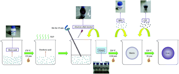
Boric acid, polydimethylsiloxane (PDMS), absolute ethyl alcohol and cross-linked agent benzoyl peroxide (BPO), purchased from Sinopharm Chemical Reagent Co., Ltd., Shanghai, China, were used to prepare the silicon–boron copolymer matrix. CIP with an average particle size of 3.5 μm was purchased from Jiangsu Tianyi Ultra-fine Metal Powder Co., Ltd., Xuyi, China. All the materials were analytically pure, and the rheological properties were tested by an MCR series rheometer (Anton Paar Co., Austria).Preparation process and the properties
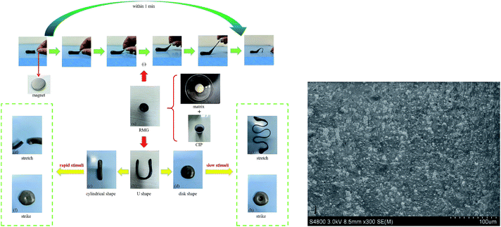
The RMG preparation process and the raw materials are shown in Fig. 1. The shear thickening and magnetorheological properties and the scanning electron microscope (SEM) image of the RMG prepared are show in Fig. 2.The prepared RMG sample is shown in Fig. 2(a). It can be easily kneaded into any shape desired, such as a cylindrical shape, U shape or disk shape, as shown in Fig. 2(b–d). If a rapid impulsive load or shock is applied to the RMG, it will stiffen to resist the external force, as shown in Fig. 2(e) and (f). In contrast, if a slow stimulus is applied to it, it will be easily drawn into a fine filament, as in Fig. 2(g), or squeezed to form a deep hole, as in Fig. 2(h). Under a magnetic field, its shape will quickly change along the magnetic induction line, as demonstrated in Fig. 2(i). The added CIPs are uniformly dispersed in the matrix, as shown in Fig. 2(j). The light or deep in black is concerned with the CIP content added in the preparation procedure. In addition, whether the CIPs can move easily in the matrix is directly related to the magnetorheological effect of the sample.
The importance of the curing process
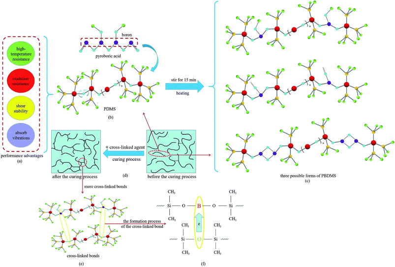
According to recent studies, the B–O cross-linked bonds between different molecular chains play a key role in the shear thickening property.39,40,50,51 The cross-linked bonds cause the single linear chains to form a net structure, similar to their function of the curing process used in the rubber industry. To study the influence of the curing process on this gel with shear thickening performance, several samples were prepared and tested. In the preparation process in Fig. 1, the CIP is merely related to the magnetorheological effect and will not be considered in the following comparative experiments.To evaluate the shear thickening performance, the relative shear thickening effect (RSTE) and absolute shear thickening effect (ASTE) are used,36,42,52 as defined in eqn (1) and (2) as follows:
 | (1) |
 | (2) |
 is the maximum shear storage modulus excited by the loading frequency and
  is the initial shear storage modulus.
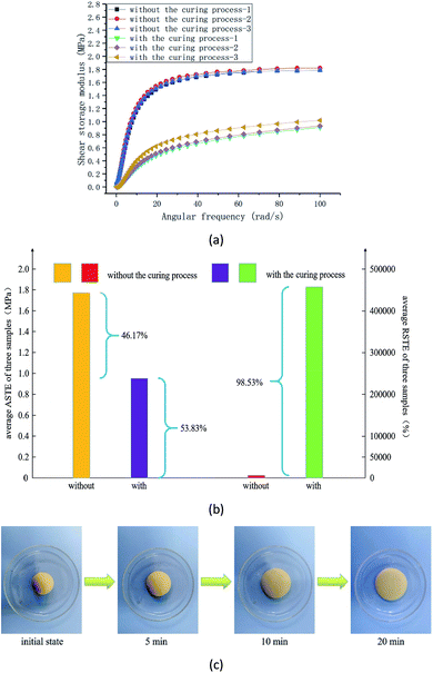
In the experiment, the other preparation conditions and the size of the specimen are all the same whether it is cured or not. Three groups of samples were prepared under two conditions. The shear storage modulus, ASTE and RSTE values, and the relaxation in a natural state are shown in Fig. 3.
The shear storage modulus of six groups of specimens under different curing conditions are demonstrated in Fig. 3(a). It is obvious that the shear storage modulus increases with the increasing angular frequency. To compare the properties of the samples, the average RSTE, ASTE values under different curing conditions and their changing rules are shown in Fig. 3(b). The RSTE reflects the adjustable ability of the material under the excitation of a variable shear rate and the ASTE indicates the overall mechanical properties. After the curing process, the ASTE is less than a half of that before curing, but the RSTE is dozens of times greater than that before curing, which demonstrates that the materials have a better ability to resist the external high-speed load. For the samples that underwent the curing process, the relative shear thickening effect is increased by up to 6717.50%. As a result, the RSTE, that is, the ability to resist the external shock or impulsive load, of RMG is greatly improved by this curing process. After the curing process, the relaxation of the sample in a natural state in shown Fig. 3(c).
In the preparation process, when the PDMS reacts with pyroboric acid, the Si–O bonds in the PDMS break, and boron is simultaneously introduced into the chains to form polyborondimethylsiloxane (PBDMS).42,53 In the curing process of the sample, the linear molecular chains are inclined to form a three-dimensional network structure by forming cross-linked bonds between the PDMS and PBDMS. The performance advantages of the materials, structures, the possible forms of the PBDMS and the molecular chains before and after the curing process are shown in Fig. 4.
In the curing process, curing temperature and time are two major parameters. Whether the selection of a parameter is reasonable is directly related to the shear thickening performance. To achieve a better property, 16 groups of samples under different curing conditions were prepared and tested.
The parameter optimization in the curing process
In the experiment, the parameters selected in the curing process are approximate. For parameter optimization, the samples are divided into 16 groups according to the different curing temperatures and time. All the samples are 2 mm in diameter and 1 mm in thickness. The results are shown in Fig. 5. | ||
| Fig. 5 The shear storage modulus of the continuously changing angular frequency from 0.1–100 rad s−1 at (a) 100 °C, (b) 110 °C, (c) 120 °C and (d) 130 °C for different curing times. | ||
During the testing procedure, the maximum shear storage modulus was relatively stable, and the initial shear storage modulus was relatively small and thus was easily affected by the environment and the experimental error. Therefore, the RSTE value is greatly affected by the initial storage modulus and shows a large fluctuation range. The conditions corresponding to the four largest values in the RSTE are 807![[thin space (1/6-em)]](https://www.rsc.org/images/entities/char_2009.gif) 353.42% at 100 °C for 45 min, 758
353.42% at 100 °C for 45 min, 758![[thin space (1/6-em)]](https://www.rsc.org/images/entities/char_2009.gif) 874.36% at 120 °C for 45 min, 758
874.36% at 120 °C for 45 min, 758![[thin space (1/6-em)]](https://www.rsc.org/images/entities/char_2009.gif) 874.36% at 130 °C for 30 min and 753
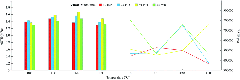
874.36% at 130 °C for 30 min and 753![[thin space (1/6-em)]](https://www.rsc.org/images/entities/char_2009.gif) 523.19% at 120 °C for 20 min. Clearly, to obtain a better RSTE, a curing time of at least 20 min is needed. When the curing time is 10 min, the RSTE is at relatively weak at any curing temperature, as shown in Fig. 6.
523.19% at 120 °C for 20 min. Clearly, to obtain a better RSTE, a curing time of at least 20 min is needed. When the curing time is 10 min, the RSTE is at relatively weak at any curing temperature, as shown in Fig. 6.
Compared with the RSTE, the ASTE is more related to the maximum shear storage modulus. Fig. 6 demonstrates that the ASTE is at a relatively high value for a curing time of 30 min at 110 °C, 120 °C and 130 °C. When the curing time is more than 30 min, the ASTE decreases, even if the temperature is 100 °C. The mean ASTE value of the four groups of samples reached a maximum at a curing temperature and time of 120 °C and 30 min. Therefore, to obtain a better ASTE, the curing temperature is set to 120 °C, and the curing time is selected to be 30 min.
The RSTE is more easily affected by the initial shear storage modulus, and the change rules are more complicated than those of the ASTE. However, in the right half of Fig. 6, the red line remains low in the plot and it is obvious that a curing time of at least 20 min is necessary for a better RSTE. In addition, considering the average results, a curing temperature of 120 °C is reasonable.
After parameter optimization for the curing process, the shear thickening performance shows a satisfactory result, with the storage modulus increasing from 101 or 102 to 106 Pa. The RSTE and ASTE reached maximum values of 1![[thin space (1/6-em)]](https://www.rsc.org/images/entities/char_2009.gif) 349
349![[thin space (1/6-em)]](https://www.rsc.org/images/entities/char_2009.gif) 380.97% and 1.170 MPa, respectively. The storage modulus of the shear thickening composites prepared by Wang et al. in recent years was increased from 102 to 106 Pa.42 The modulus of Silly Putty prepared by Martin et al. exceeded 105 Pa at high frequencies.38 The magnetorheological Silly Putty fabricated by Guo et al. displayed a maximum ASTE value of 0.805 MPa at 10 °C and a maximum RSTE value of 6600% at 60 °C.52 The shear storage modulus of Silly Putty prepared by Xu et al. changed by four orders of magnitude.54 The storage modulus of a rate-dependent and self-healing conductive shear stiffening nanocomposite fabricated by Wang et al. increased by 4 orders of magnitude under external shear stimuli, and the maximum shear storage modulus exceeded 1 MPa.36 In the preparation process of RMG, the cross-linked density is the number of the cross-linked bonds formed in the composite and is directly related to the performance of the sample. For the B–O cross-linked bonds (B from pyroboric acid and O from PDMS), the cross-linked density can be adjusted by changing the mass ratio of pyroboric acid to PDMS.
380.97% and 1.170 MPa, respectively. The storage modulus of the shear thickening composites prepared by Wang et al. in recent years was increased from 102 to 106 Pa.42 The modulus of Silly Putty prepared by Martin et al. exceeded 105 Pa at high frequencies.38 The magnetorheological Silly Putty fabricated by Guo et al. displayed a maximum ASTE value of 0.805 MPa at 10 °C and a maximum RSTE value of 6600% at 60 °C.52 The shear storage modulus of Silly Putty prepared by Xu et al. changed by four orders of magnitude.54 The storage modulus of a rate-dependent and self-healing conductive shear stiffening nanocomposite fabricated by Wang et al. increased by 4 orders of magnitude under external shear stimuli, and the maximum shear storage modulus exceeded 1 MPa.36 In the preparation process of RMG, the cross-linked density is the number of the cross-linked bonds formed in the composite and is directly related to the performance of the sample. For the B–O cross-linked bonds (B from pyroboric acid and O from PDMS), the cross-linked density can be adjusted by changing the mass ratio of pyroboric acid to PDMS.
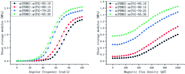
In the recent study, the curing process and the cross-linked density were proved to be related to the storage modulus.55 In this paper, the samples with or without the curing process obviously possess different cross-linked densities. The shear storage modulus of the material shows a better performance at a curing temperature of 110–120 °C and for a curing time at 20–30 min, respectively. The results indicate that the cross-linked density can be improved by optimizing the parameters in the preparation process and the storage modulus of the sample attains the values in the range of 1.3–1.7 MPa.
The change rules of the properties
To evaluate their magnetorheological properties, the relative magnetorheological effect (RMRE) and absolute magnetorheological effect (AMRE) are defined as follows:
 | (3) |
| AMRE = Gmax − Gmin | (4) |
In the experiment, the angular frequency of the rheometer is positively correlated with the shear rate. With increasing magnetic flux density, the CIP gradually forms a chain structure in the matrix, which leads to an increasing storage modulus and magnetorheological effect.
The change rules of the performance indexes are shown in Fig. 8. In general, the ASTE values of all the samples range from 1.5 MPa to 2.0 MPa, and the RSTE values decrease several orders of magnitude with increasing PA content. In addition, all the AMRE values are less than 1.0 MPa. The RMRE values decrease obviously with increasing PA content, but the extent of the decline is less than that of the RSTE values.
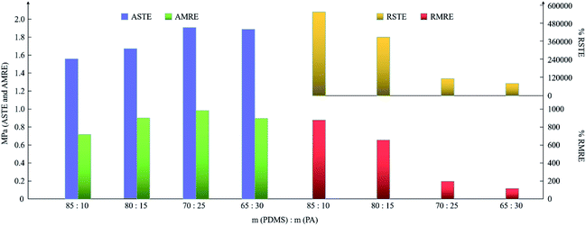 | ||
| Fig. 8 The change rules of the ASTE, AMRE, RSTE and RMRE of the samples with different ratios of PDMS to PA. | ||
When m(PDMS)![[thin space (1/6-em)]](https://www.rsc.org/images/entities/char_2009.gif) :
:![[thin space (1/6-em)]](https://www.rsc.org/images/entities/char_2009.gif) m(PA) is 85
m(PA) is 85![[thin space (1/6-em)]](https://www.rsc.org/images/entities/char_2009.gif) :
:![[thin space (1/6-em)]](https://www.rsc.org/images/entities/char_2009.gif) 10, the ASTE and RSTE values indicate that the material is relatively soft due to the small ASTE and has a larger adjustment range because of the high RSTE. With an increasing amount of B atoms in the matrix, the available space for the movement of the molecular chains decreases, resulting in the hardening of the matrix and an increase in the ASTE. Similarly, the RSTE decreases with decreasing available movement space of the chains. The more B atoms in the matrix, the more difficult it is for CIP to move freely to form an ordered structure, therefore resulting in a decrease in the RMRE. Obviously, the RSTE and RMRE decrease significantly with the decreasing m(PDMS)
10, the ASTE and RSTE values indicate that the material is relatively soft due to the small ASTE and has a larger adjustment range because of the high RSTE. With an increasing amount of B atoms in the matrix, the available space for the movement of the molecular chains decreases, resulting in the hardening of the matrix and an increase in the ASTE. Similarly, the RSTE decreases with decreasing available movement space of the chains. The more B atoms in the matrix, the more difficult it is for CIP to move freely to form an ordered structure, therefore resulting in a decrease in the RMRE. Obviously, the RSTE and RMRE decrease significantly with the decreasing m(PDMS)![[thin space (1/6-em)]](https://www.rsc.org/images/entities/char_2009.gif) :
:![[thin space (1/6-em)]](https://www.rsc.org/images/entities/char_2009.gif) m(PA), and ASTE and AMRE are less affected by this ratio. That is to say, in the field of application, adding more PDMS in the preparation process is useful to the ability to resist the external load.
m(PA), and ASTE and AMRE are less affected by this ratio. That is to say, in the field of application, adding more PDMS in the preparation process is useful to the ability to resist the external load.
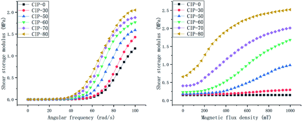 | ||
| Fig. 9 The shear storage modulus with a continuously changing angular frequency from 0.1–100 rad s−1 and a continuously changing magnetic flux density from 0–1000 mT for different CIP qualities. | ||
For the samples without the CIP, i.e., the silicon–boron copolymer, the RSTE value reaches a maximum of 1![[thin space (1/6-em)]](https://www.rsc.org/images/entities/char_2009.gif) 349
349![[thin space (1/6-em)]](https://www.rsc.org/images/entities/char_2009.gif) 380.97%, which is much higher than that of the other samples.
380.97%, which is much higher than that of the other samples.
The ASTE and AMRE values increase with increasing CIP quality, and the rate of increase in the AMRE values is higher than that of the ASTE values. With increasing CIP, there is a rapid increase in the initial zero-field shear storage modulus. Therefore, the RMRE values first increase and then decrease. After CIP is added to the matrix, the RSTE values gradually decrease from 760![[thin space (1/6-em)]](https://www.rsc.org/images/entities/char_2009.gif) 538.00% to 357
538.00% to 357![[thin space (1/6-em)]](https://www.rsc.org/images/entities/char_2009.gif) 042.86%. The performance indexes and the change rules are shown in Fig. 10.
042.86%. The performance indexes and the change rules are shown in Fig. 10.
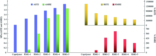 | ||
| Fig. 10 The change rules of the ASTE, AMRE, RSTE and RMRE of the samples with different CIP contents. | ||
According to the results shown in Fig. 10, there is a rapid rate of increase in the AMRE when the CIP content is less than 60 wt%. Interestingly, when the CIP content is 60 wt%, the RMRE can reach a maximum value of 630.43%. Furthermore, the increase rate of AMRE will also slow down after the CIP content is more than 60 wt%. Therefore, to improve the magnetorheological performance, 60 wt% CIP content is preferred composition.
Conclusions
As a kind of smart material with stimuli-responsive performance, the properties of RMG will change under a external magnetic field or a rapid shear stimuli. In the presence of a magnetic or electrical field, the property of this materials can be actively adjusted. Once in the case of a circuit failure, the materials can passively respond to the external rapid shear stimuli and harden in a short time. Because this kind of materials possess tunable properties, they are candidates for applications in vibration control, shock transmission unit, damping and body armor.In this work, a type of rate-sensitive and magnetic-sensitive gel was prepared by uniformly dispersing CIP into a silicon–boron copolymer matrix. In the preparation process, a curing process used in the rubber industry was included. After the curing process, when the absolute shear thickening effect drops by less than half, the relative shear thickening effect can be increased by 6717.50%. The parameters considered in the curing process were also optimized. To obtain a better shear thickening effect, a curing temperature of 120 °C, and a curing time of 30 min were selected. With an increasing m(PDMS)![[thin space (1/6-em)]](https://www.rsc.org/images/entities/char_2009.gif) :
:![[thin space (1/6-em)]](https://www.rsc.org/images/entities/char_2009.gif) m(PA), the adjustability decreases, but the mechanical properties improve. Finally, to improve the magnetorheological effect, 60 wt% CIP content should be selected in the preparation process.
m(PA), the adjustability decreases, but the mechanical properties improve. Finally, to improve the magnetorheological effect, 60 wt% CIP content should be selected in the preparation process.
Conflicts of interest
There are no conflicts to declare.Acknowledgements
The authors gratefully acknowledge support from the Jiangsu Province Key R&D Project (grant no. BE2017167), the Fundamental Research Funds for the Central Universities (2018B48514) and the Innovative Talents Training Project for College Students (2019102941315). This study was also supported by Kang Kang in Hohai University.References
- E. Brown, N. A. Forman, C. S. Orellana, H. J. Zhang, B. W. Maynor, D. S. Betts, J. M. DeSimone and H. M. Jaeger, Nat. Mater., 2010, 9, 220–224 CrossRef CAS PubMed.
- H. A. Barnes, J. Rheol., 1989, 33, 329–366 CrossRef CAS.
- R. Cross, Am. J. Phys., 2012, 80, 870–875 CrossRef CAS.
- D. Y. Wu, S. Meure and D. Solomon, Prog. Polym. Sci., 2008, 33, 479–522 CrossRef CAS.
- R. L. Hoffman, Trans. Soc. Rheol., 1972, 16, 155–173 CAS.
- R. L. Hoffman, J. Colloid Interface Sci., 1974, 46, 491–506 CrossRef CAS.
- E. Brown and H. M. Jaeger, Rep. Prog. Phys., 2014, 77, 046602 CrossRef PubMed.
- J. Rabinow, Trans. Am. Inst. Electr. Eng., 1948, 67, 1308–1315 Search PubMed.
- T. Shiga, A. Okada and T. Kurauchi, J. Appl. Polym. Sci., 1995, 58, 787–792 CrossRef CAS.
- X. G. Lin, F. Guo, C. B. Du and G. J. Yu, Adv. Mater. Sci. Eng., 2018, 2681461 Search PubMed.
- J. Liang and X. H. Zhang, J. Mater. Civ. Eng., 2015, 27, 04014250 CrossRef.
- H. M. Pang, S. H. Xuan, C. L. Sun and X. L. Gong, Smart Mater. Struct., 2017, 26, 105017 CrossRef.
- N. Hoang, N. Zhang and H. Du, Smart Mater. Struct., 2009, 18, 074009 CrossRef.
- Z. B. Xu, X. L. Gong, G. J. Liao and X. M. Chen, J. Intell. Mater. Syst. Struct., 2010, 21, 1039–1047 CrossRef.
- X. Z. Zhang, W. H. Li and X. L. Gong, Smart Mater. Struct., 2008, 17, 035027 CrossRef.
- T. F. Tian and M. Nakano, Smart Mater. Struct., 2017, 26, 035038 CrossRef.
- F. D. Goncalves, M. Ahmadian and J. D. Carlson, Smart Mater. Struct., 2006, 15, 75–85 CrossRef.
- S. J. Mcmanus, K. A. S. Clair, P. E. Boileau, J. Boutin and S. Rakheja, J. Sound Vib., 2002, 253, 313–327 CrossRef.
- M. J. Wilson, A. Fuchs and F. Gordaninejad, J. Appl. Polym. Sci., 2002, 84, 2733–2742 CrossRef CAS.
- A. Fuchs, M. Xin, F. Gordaninejad, X. J. Wang, G. H. Hitchcock, H. Gecol, C. Evrensel and G. Korol, J. Appl. Polym. Sci., 2004, 92, 1176–1182 CrossRef CAS.
- H. X. Deng and X. L. Gong, Commun. Nonlinear Sci. Numer. Simulat., 2007, 13, 1938–1947 CrossRef.
- N. Hoang, N. Zhang and H. Du, Smart Mater. Struct., 2009, 18, 074009 CrossRef.
- P. P. Phulé, M. P. Mihalcin and S. Genc, J. Mater. Res., 1999, 14, 3037–3041 CrossRef.
- I. B. Jang, H. B. Kim, J. Y. Lee, J. Y. You, H. J. Choi and M. S. Jhon, J. Appl. Phys., 2005, 97, 10Q912 CrossRef.
- Y. S. Lee, E. D. Wetzel and N. J. Wagner, J. Mater. Sci., 2003, 38, 2825–2833 CrossRef CAS.
- K. Talreja, I. Chauhan, A. Ghosh, A. Majumdar and B. S. Butola, RSC Adv., 2017, 7, 49787–49794 RSC.
- E. S. Guler, Bull. Mater. Sci., 2018, 41, 112 CrossRef.
- H. R. Baharvandi, M. S. Meydari, N. Kordani, M. Alebooyeh, M. Alizadeh and P. Khaksari, J. Text. Inst., 2016, 183, 397–407 Search PubMed.
- N. Asija, H. Chouhan, S. A. Gebremeskel, R. K. Singh and N. Bhatnagar, Int. J. Impact Eng., 2017, 110, 359–364 CrossRef.
- X. F. Liu, M. Q. Li, X. Li, X. B. Deng, X. H. Zhang, Y. Yan, Y. L. Liu and X. Chen, J. Mater. Sci., 2018, 53, 7357–7371 CrossRef CAS.
- E. Balali, N. Kordani and A. S. Vanini, J. Text. Inst., 2017, 108, 376–384 CrossRef CAS.
- M. Hasanzadeh, V. Mottaghitalab, M. Rezaei and H. Babaei, Thin-Walled Struct., 2017, 119, 700–706 CrossRef.
- J. H. Jang, C. K. Ullal, T. Choi, M. C. Lemieux, V. V. Tsukruk and E. L. Thomas, Adv. Mater., 2006, 18, 2123–2127 CrossRef CAS.
- R. Cross, Am. J. Phys., 2012, 80, 870–875 CrossRef CAS.
- M. P. Goertz, X. Y. Zhu and J. E. Houston, J. Polym. Sci., Part B: Polym. Phys., 2009, 47, 1285–1290 CrossRef CAS.
- S. Wang, S. H. Xuan, W. Q. Jiang, W. F. Jiang, L. X. Yan, Y. Mao, M. Liu and X. L. Gong, J. Mater. Chem. A, 2015, 3, 19790–19799 RSC.
- S. Wang, S. H. Xuan, Y. P. Wang, C. H. Xu, Y. Mao, M. Liu, L. F. Bai, W. Q. Jiang and X. L. Gong, ACS Appl. Mater. Interfaces, 2016, 8, 4946–4954 CrossRef CAS PubMed.
- R. Martin, A. Rekondo, A. R. D. Luzuriaga, A. Santamaria and I. Odriozola, RSC Adv., 2015, 5, 17514–17518 RSC.
- Z. Liu, S. J. Picken and N. A. M. Besseling, Macromolecules, 2014, 47, 4531–4537 CrossRef CAS.
- B. Liu, C. B. Du, G. J. Yu and Y. K. Fu, Smart Mater. Struct., 2020, 29, 015004 CrossRef.
- L. N. Zou, X. Cheng, M. L. Rivers, H. M. Jaeger and S. R. Nagel, Science, 2009, 326, 408–410 CrossRef CAS PubMed.
- S. Wang, W. Q. Jiang, W. F. Jiang, F. Ye, Y. Mao, S. H. Xuan and X. L. Gong, J. Mater. Chem. C, 2014, 2, 7133–7140 RSC.
- S. S. Zhang, S. Wang, T. Hu, S. H. Xuan, H. Jiang and X. L. Gong, Composites, Part B, 2019, 180, 107564 CrossRef.
- W. Q. Zhao, Y. Wang and X. L. Gong, Smart Mater. Struct., 2019, 28, 105033 CrossRef.
- N. Golinelli, A. Spaggiari and E. Dragoni, J. Intell. Mater. Syst. Struct., 2017, 28, 953–960 CrossRef CAS.
- W. F. Jiang, X. L. Gong, S. Wang, Q. Chen, H. Zhou, W. Q. Jiang and S. H. Xuan, Appl. Phys. Lett., 2014, 104, 121915 CrossRef.
- C. S. Boland, U. Khan, G. Ryan, S. Bawich, R. Charifou, A. Harvey, C. Backes, Z. L. Li, M. S. Ferreira, M. E. Möbius, R. J. Young and J. N. Coleman, Science, 2016, 354, 1257–1260 CrossRef CAS PubMed.
- X. W. Fan, S. Wang, S. S. Zhang, Y. Wang and X. L. Gong, J. Mater. Sci., 2019, 54, 6971–6981 CrossRef CAS.
- M. Liu, S. S. Zhang, S. Liu, S. S. Cao, S. Wang, L. F. Bai, M. Sang, S. H. Xuan, W. Q. Jiang and X. L. Gong, Composites, Part A, 2019, 126, 105612 CrossRef CAS.
- Y. P. Wang, S. Wang, C. H. Xu, S. H. Xuan, W. Q. Jiang and X. L. Gong, Compos. Sci. Technol., 2016, 127, 169–176 CrossRef CAS.
- Y. P. Wang, L. Ding, C. Y. Zhao, S. Wang, S. H. Xuan, H. Jiang and X. L. Gong, Compos. Sci. Technol., 2018, 168, 303–311 CrossRef CAS.
- F. Guo, C. B. Du, G. J. Yu and R. P. Li, Adv. Mater. Sci. Eng., 2016, 7079698 Search PubMed.
- T. I. Zatsepina, M. L. Brodskii, Y. A. Frolova, A. A. Trapeznikov, V. N. Gruber and G. A. Kruglova, Polym. Sci., 1970, 12, 2899–2905 Search PubMed.
- C. H. Xu, Y. Wang, J. Wu, S. C. Song, S. S. Cao, S. H. Xuan, W. Q. Jiang and X. L. Gong, Compos. Sci. Technol., 2017, 153, 168–177 CrossRef CAS.
- P. Georgopanos, G. A. Schneider, A. Dreyer, U. A. Handge, V. Filiz, A. Feld, E. D. Yilmaz, T. Krekeler, M. Ritter, H. Weller and V. Abetz, Sci. Rep., 2017, 7, 7314 CrossRef PubMed.
| This journal is © The Royal Society of Chemistry 2020 |

