
 Open Access Article
 This Open Access Article is licensed under a
 Creative Commons Attribution 3.0 Unported Licence
Advances in passively driven microfluidics and lab-on-chip devices: a comprehensive literature review and patent analysis
Vigneswaran Narayanamurthy *abc,
Z. E. Jeroishde,
K. S. Bhuvaneshwaridf,
Pouriya Bayatg,
R. Premkumard,
Fahmi Samsurie and
Mashitah M. Yusoffh
*abc,
Z. E. Jeroishde,
K. S. Bhuvaneshwaridf,
Pouriya Bayatg,
R. Premkumard,
Fahmi Samsurie and
Mashitah M. Yusoffh
aDepartment of Electronics and Computer Engineering Technology, Faculty of Electrical and Electronic Engineering Technology, Universiti Teknikal Malaysia Melaka, Hang Tuah Jaya, 76100 Durian Tunggal, Melaka, Malaysia. E-mail: vigjes@gmail.com; vigneswaran@utem.edu.my
bInnoFuTech, No: 42/12, 7th Street, Vallalar Nagar, Chennai, Tamil Nadu 600072, India
cCentre of Excellence for Advanced Research in Fluid Flow, University Malaysia Pahang, Kuantan 26300, Malaysia
dDepartment of Biomedical Engineering, Rajalakshmi Engineering College, Chennai 602105, India
eFaculty of Electrical and Electronics Engineering, University Malaysia Pahang, Pekan 26600, Malaysia
fFaculty of Electronics and Computer Engineering, Universiti Teknikal Malaysia Melaka, Hang Tuah Jaya, 76100 Durian Tunggal, Melaka, Malaysia
gDepartment of Bioengineering, McGill University, Montreal, QC, Canada H3A 0E9
hFaculty of Industrial Sciences and Technology, University Malaysia Pahang, Kuantan 26300, Malaysia
First published on 23rd March 2020
Abstract
The development of passively driven microfluidic labs on chips has been increasing over the years. In the passive approach, the microfluids are usually driven and operated without any external actuators, fields, or power sources. Passive microfluidic techniques adopt osmosis, capillary action, surface tension, pressure, gravity-driven flow, hydrostatic flow, and vacuums to achieve fluid flow. There is a great need to explore labs on chips that are rapid, compact, portable, and easy to use. The evolution of these techniques is essential to meet current needs. Researchers have highlighted the vast potential in the field that needs to be explored to develop rapid passive labs on chips to suit market/researcher demands. A comprehensive review, along with patent analysis, is presented here, listing the latest advances in passive microfluidic techniques, along with the related mechanisms and applications.
Introduction
Handling small volumes of fluids is very important in high-throughput screening, diagnosis, and research applications.1 Microfluidics is one way to handle small volumes of fluids between microlitres (10−6) and picolitres (10−12).2–4 Hundreds of simultaneous biochemical reactions can be performed in a collection of microarrays arranged on a solid substrate which acts as laboratories, embedded in which are chips known as biochips.5,6 There are three main types of biochips: lab on chips (LOCs), DNA chips, and protein chips. LOCs employ a combination of one or more laboratory functions within a single integrated chip.7 Some fields utilizing LOCs, such as sub-micrometer and nano-sized channels, DNA labyrinths, single-cell detection and analysis,8 and nano-sensors, might become feasible, allowing new ways to interact with biological species and large molecules. In addition, a large number of biochemical analyses can be screened at a faster rate in disease diagnosis and the detection of bioterrorism agents.9 Several reports have been published on the various aspects of these devices, including fluid transport, system properties, sensing techniques,10 and bioanalytical applications. Advantages11,12 include lower fabrication costs, allowing cost-effective disposable chips and mass production. Simple tests that could be performed by the bedside are known as point-of-care (POC) testing.13 The ultimate aim of this technique is to obtain results in a concise period at or near the location of the patient, so that the treatment plan can be adjusted.14 Microfluidics can be used for various lab experiments, such as drug testing and discovery,15–23 filtration and separation of particles,24 cell sorting and counting,25–31 cell culture,32–40 point-of-care diagnosis,41,42 3D printing, stoichiometry, and flow synthesis.43,44 Due to their simplicity with high throughput and very low reagent consumption,45 microfluidic chips are vital components in research, for the delivery of accurate results.46 Microfluidic chips are mostly made up of PDMS (polydimethylsiloxane). PDMS is commonly used because it is a transparent elastic polymer, permeable to oxygen and carbon dioxide.47–51 Additionally, PDMS is now becoming a standard material as it can be easily fabricated for microfluidic devices (MFDs), and its high gas solubility, which obeys Henry's law, is a significant advantage of using PDMS material.52Microfluidic operation techniques
The techniques assisting fluid flow in an MFD are generally classified as active or passive.53,54 Active microfluidics55,56 involves the movement or transport of biological samples and analysis of those samples through an external power source/field57–59 or actuators,60 such as peristaltic pumps,61 electro-kinetics,62,63 electro-wetting,64 electro-osmotic pumps,65 electrostatics,66,67 centrifugal and magnetic pumps68 and some other large power sources to power the pumps and actuators.69–71 Thus the complexity of structure and size is increased, which requires additional human resources. Hence, the probability of integrating active microfluidics with LOCs and (POC) applications has dropped off. To counter these drawbacks,72–74 the movement of the test sample is achieved either using fluid properties or passive mechanisms without any external supporting power sources. Hence, passive microfluidics75 has been adopted and used to a large extent in modern-day research projects to avoid the use of external supporting power devices. This method is simple, easy to manufacture, and does not need any actuators or external power supplies, as it employs basic laboratory instruments, like micropipettes, and medical devices, such as syringe pumps.Systematic literature search
A systematic literature search has been performed using Google Scholar with the following keywords: “passive pumping platform, passively driven microfluidics, pressure head driven microfluidics, and flow-driven microfluidics” throughout 2000–2018. Fig. 1 presents a pie chart revealing the aggregate number of articles on passive microfluidics published from 2000 to 2018. This review article will be useful for researchers who plan further investigations in this field.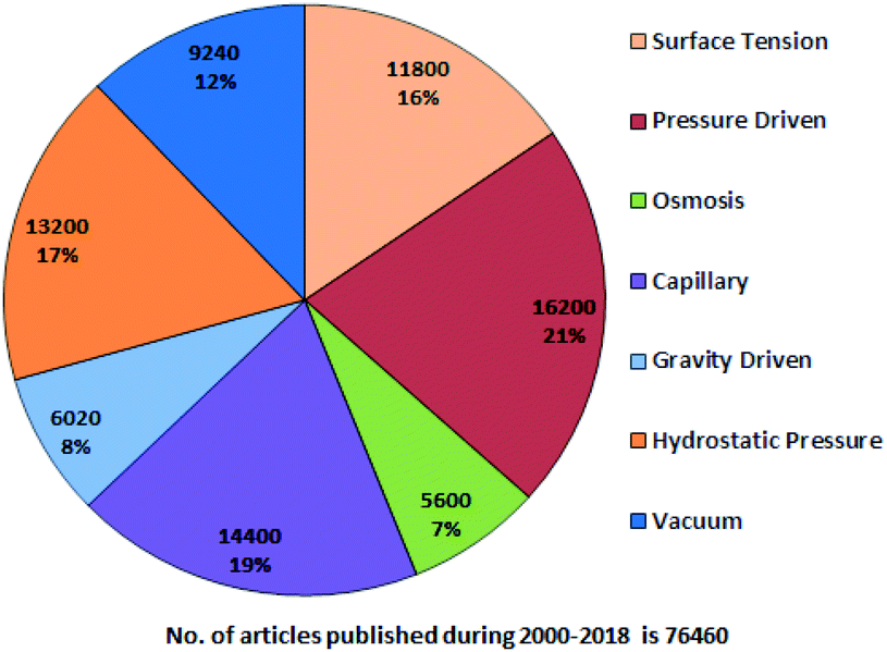 | ||
| Fig. 1 Trends in passive microfluidics. | ||
From Fig. 1, it is evident that pressure-driven, capillary, hydrostatic, surface-tension and vacuum-based methods are leading trends. From the search, articles were selected and some were hand picked based on their relevancy with an exclusive focus on the passively driven approach and they are presented according to their timeline. In 2002, David Beebe et al. published a short report on the fabrication of MFDs and the physics applied to passive valves, mixers, and pumps which facilitate fluid flow.53 Due to the extensive usage of PDMS in MFDs, Sia et al. reviewed the advantages of using PDMS in miniaturized biological assay devices, such as efficiency and spectral insights into cell biology, where the fluidic flow was obtained by applying a positive or negative pressure at the inlet or outlet, respectively.76 Subsequently, Bayraktar et al. reviewed the available knowledge based on the areas that required additional investigation in pressure-driven and electro-osmotic flows in microchannels.77 Later, Fiorini et al. in 2005 reported a review of different modes of on-chip operations, such as the pumping and valving of fluid flow; and the separation and detection of different chemical species that have been implemented in a microfluidic format.54 Haeberle et al. reported platforms for LOC applications.78 Eventually, a microfluidic cell culture was developed, which implied the use of surface tension, where a differential pressure was generated due to the different volumes in the inlet and outlet port to assist the fluid flow and which was based on concepts related to physical and microenvironments on passive pumping.79 Additionally, Ahn et al. reported a short review in 2010 based on various methods of passive pumping and their applications to LOC biochemical analysis.80
Furthermore, Gervais et al. focused on various techniques that have been adapted for passive pumping.74 Later, Su et al. reviewed the latest advances in microfluidic platforms for POC testing in the context of infectious diseases, along with the integration of multiple functions into a single unit with full automation and analysed the challenges involved.81 Subsequently, Byun et al. summarized recent advances in pumping techniques for microfluidic cell culture in an effort to support current and potential users of microfluidic-based devices for advanced in vitro cellular studies.57 The relevant biophysical laws, along with their experimental details and the designs of various passive separation techniques, were explained by Tripathi et al. in 2015.82 These separation techniques advanced the development of single-cell capture. Eventually, Narayanamurthy et al. focussed on the development of single-cell trapping using hydrodynamic effects for the purpose of developments in cell separation and rapid viral detection and explained its benefits.83
In this article, we wish to discuss the current proposals, developments, updates, and future of passive microfluidic and LOC devices. The different methods adopted in every passively driven type of microfluidics are briefly covered, so that one can obtain a better and clearer knowledge of previous techniques.84–86 This also throws light on the advantages, flow rates and applications of all the techniques. The limitations of each method are also explained.
Patent analysis and current key market players in the field of microfluidics and lab-on-chip devices
A patent analysis was performed with the Google Patents search tool, using the keywords, passive AND (driven OR flow) AND (biochips OR microfluidics OR LOC), and the analysis is provided in Fig. 2. The key players in the microfluidics market are Semiconductor Energy Laboratory Co., Ltd. (US), Theranos, Inc. (US), Abbott Point Of Care Inc. (US), Micronics, Inc. (US), Danaher (US), Thermo Fisher (US), PerkinElmer (US), Roche (Switzerland), Biomicro Systems, Inc. (US), Incyte Genomics, Inc. (US), Silicon Laboratories, Inc. (US), Tecan Trading Ag (Switzerland), Aviva Biosciences Corporation (US), Eksigent Technologies, Llc (US), Nanostream, Inc. (US), International Business Machines Corporation (US), 10X Genomics (US), Accelerate Diagnostics, Inc. (US), Advanced Cell Diagnostics, Inc. (US), Affymetrix, Inc. (US), Agilent Technologies, Inc. (US), Amphasys AG (Switzerland), Angle Plc (UK), Beckman Coulter, Inc. (US), Becton, Dickinson, and Company (US), Bio-Rad Laboratories, Inc. (US), Clontech Laboratories, Inc. (US), Celsee Diagnostics (US), Enumeral (US), Epic Sciences (US), Fluidigm (US), Illumina, Inc. (US), Kellbenx Inc. (US), Merck KGaA (Germany), NanoString technologies (US), Qiagen NV (Netherlands), Sigma Aldrich (US), Thermo Fisher Scientific, Inc. (US), Wafergen Bio-Systems, Inc. (US), Yikon Genomics (China), Zephyrus Biosciences, Inc. (US), Dolomite Microfluidics (UK), GYROS PROTEIN TECHNOLOGIES AB (Sweden), Sphere Fluidics (UK), OPKO Health (US), Waters (US), thinXXS Microtechnology (Germany), Abaxis (US), bioMérieux (France), Dolomite Microfluidics (UK), Microfluidic ChipShop (Germany), Elveflow (France), Cellix (Ireland), Micronit Microtechnologies (Netherlands), MicroLiquid (Spain), MiniFAB (Australia), uFluidix (Canada), Micralyne (US), and Fluigent (France).87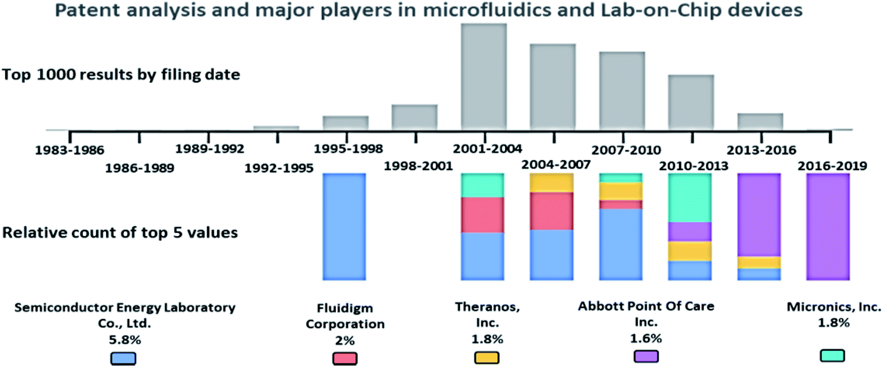 | ||
| Fig. 2 Patent analysis of passively driven microfluidics and LOC devices. | ||
Passive microfluidic techniques
Passive microfluidics is an emerging technique with a tremendous scope that is being adopted more commonly in LOC and POC diagnosis due to the following characteristics:• Easy fabrication: Fabrication of passive microfluidics is simple and easy, as it avoids complicated fabrication resulting in complex structures.
• Less expertise: Passive microfluidics operation does not usually require training or experience, as it is straightforward and easy to operate.
• No external power source required: Passive microfluidics does not involve any external power source for its working.
• Low cost: Passive microfluidics is substantially low in price due to less complicated procedures and no auxiliaries being involved.
• Compact and portable: Passive microfluidics is very compact and portable in size; hence, it can be driven almost anywhere.
Different techniques employed in the field of microfluidics and LOC devices to achieve passive operations are surface tension, pressure-driven, osmosis, capillary action, gravity-induced flow, vacuum suction, and hydrostatic pressure, as shown in Fig. 3. Each technique has its pros and cons. In the sections below, each technique is described in detail, and the articles are listed in year order.
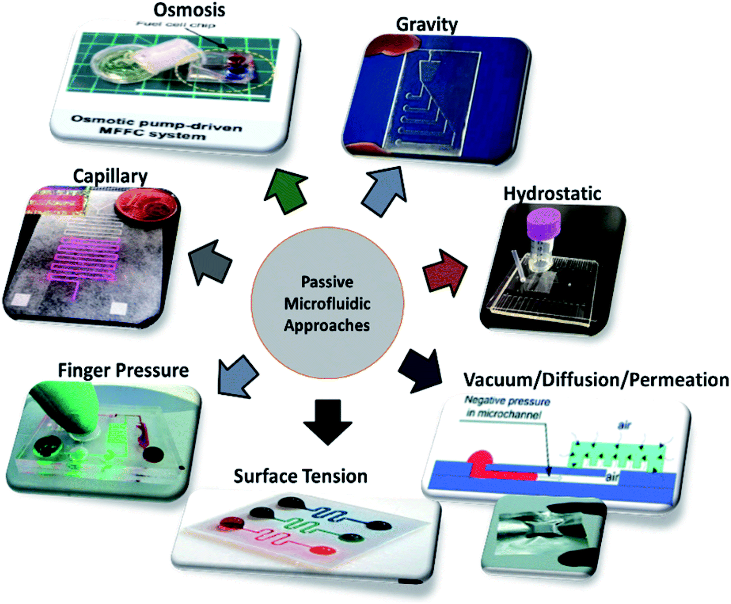 | ||
| Fig. 3 Different approaches employed in passively driven microfluidics and LOC devices. | ||
Surface tension
In general, surface tension is defined as a property of the surface of a liquid that allows it to resist an external force due to the cohesive nature of water molecules. This cohesive forces between the liquid molecules are responsible for the phenomenon known as surface tension.88In microfluidics, the generation of strong passive flows can be achieved by selecting a suitable surface and liquid combinations that can create the required solid–liquid surface-tension gradients.89 Mathematical models are required to finalize the design of the channel, so Makhijani et al. developed a numerical model to simulate the liquid filling due to the presence of surface tension in the liquid–air interface and demonstrated the application of disposable biochips for clinical diagnosis. It was mainly used for analysis and optimization to achieve the desired flow.90 Subsequently, Walker et al. proposed a simple, semi-autonomous method of pumping fluids where devices producing small droplets, such as a pipettes, were required.91 Meanwhile, evaporation occurred during the surface-tension-based flow, which could be used to increase the concentration of the sample in the channel.92 Due to the requirement of microfluid mixing, for the purpose of drug delivery and research, Chen et al. demonstrated a micromixing device without the use of any active devices; hence, the surface tension of the fluid provided transport, merging, mixing, and stopping in the microchannel by varying the channel geometry.93 Ward et al. analysed droplet formation using flow-focusing geometry and microfluidic technology and compared the two methods of supplying fluids using a syringe-pump methodology that dictated the volume flow rates and a method which controlled the inlet fluid pressure.94 Later, Tan et al. controlled the droplets by the formation of a bifurcated junction in an MFD, and thereby controlled the chemical concentration in the droplet by the use of droplet fission.95
Furthermore, a passive pumping technique was employed in a direct methanol fuel cell (DMFC), through passive fuel delivery, designed based on a surface-tension driving mechanism and integrated with a laboratory-made prototype to achieve fixed consumption depending on fuel concentration and power-free fuel delivery. Due to different surface-tension properties, water was separated from methanol through a Teflon membrane, and forward flow occurred in the capillary. This was believed by Yang et al. to be more applicable to future small-scale DMFCs in portable electronics.96 Thanks to their analysis of channel pressure and flow, Berthier et al. reported that greater pressure created a large drop in output at the channel exit when a small droplet was placed on the entrance of the microfluidic channel.97 Eventually, in 2008 Ivar et al. published an article that implied the use of surface tension to induce a pressure difference in the fluid that causes pumping, routing, and compartmentalization without the use of any additional micro-components. Moreover, they demonstrated the applications of patterning multiple monolayer cell colonies and three-dimensional cell compartments and co-cultures.98 Backflow is a serious issue faced in surface-tension-driven pumps, so Ju et al. explained the optimum conditions required to avoid backflow in surface-tension-driven passive pumping by determining the ratio of inlet and outlet pressure during the occurrence of backflow.99 Du et al. reported that the concentration gradient in the channel induced forward flow, and it was further enhanced by evaporation-induced backward flow. Thus, the gradient concentration generated was controlled by convection and molecular diffusion. This approach was particularly used for chemical and biological processes in portable MFDs, where long-range gradients are required.100 Jane et al. analysed the flow rate with the Hagen–Poiseuille equation, thermodynamics, and the Young–Laplace equation where the flow rates could be controlled by channel geometry, dimension of inlet and outlet wells and hydrophobicity. Later, Chen et al. provided a clear idea about the surface-tension-induced flow rates, theoretical relationships among sample volume, induced flow rate, and surface tension of the drops at the inlet and outlet ports, and resistance to flow.101
As soon as the droplet was placed at the inlet port, it began to collapse due to varying velocity in the channel and it transformed from a smaller drop to a larger drop. Theoretically, the maximum flow rate was obtained at a contact angle of 90 degrees, but practically it was maintained between 30 and 60 degrees due to refilling. Resto et al. provided a clear idea of both theoretical and practical aspects of the pumping and the contact angle to achieve the maximum flow rate.102 The surface tension caused a pressure difference in the channel to induce fluid flow from the inlet to the outlet. Equilibrium of pressure in the channel led to the immediate arrest of the inflow. This sudden stop allowed its use in a wide range of biological applications from reagent delivery to drug-cell studies.103 Jane et al. explained that the surface tension in the fluid induced the flow through the microchannels due to the change in volumes of fluid. Passive microfluidics with electrochemical sensors inside the microchannel was considered for LOC flow injection. Various factors affecting the flow in the microfluidic channel were also discussed. This was the first report on a passive pump based on flow injection analysis (FIA).104 In 2010, Amy et al. integrated particle counting with a passive pumping mechanism by placing a 0.5 microliter drop of saline and sample fluid on the focussing inlet and the sample inlet, respectively. The surface tension in the fluid experienced a flow due to the change in volume. These flows to the reservoir traversed a pore that caused a change in resistivity, and the pulse was counted. Thus, particle counting was achieved with the help of surface-tension pumping.105
Puccinelli et al. explained that the pumping process of a small drop placed at the inlet was due to the surface tension in the inlet fluid. They validated the performance of a complete, reliable, and repeatable cell-based biological assay. The robustness of each technique was also discussed.106 Chung et al. described the involvement of surface tension, as well as evaporation, leading to the generation of passive pumping in a forward and backward direction with a concentration gradient a few centimeters long in the channel. Recent developments in microfluidic gradient generators were also described in their work.107 Besides research, Lin et al. demonstrated the uses and applications of microfluidics in the fields of food, environment, and physiological health monitoring.108 Berthier et al. suggested that the surface tension of the fluid enabled a short-term laminar flow patterning in multiple fluids when the sample was loaded in any sequence. Numerical simulations and practical experiments were conducted to study the laminar behaviour. This method was well suited to a cell-based assay and reduced the complexities of laminar flow patterning (LPF).109 In 2012, Resto et al. developed inertia-enhanced passive pumping that reduced fluid exchange and inertia-activated flow, which initiates the flow in an empty channel where fluid flow took place due to surface tension. They also analysed the transfer of momentum to the incoming fluid and the effect which induced the pumping mechanism.110
Microdevices are capable of targeted focal delivery of chemicals for axonal growth studies. Hence, Kuo et al. varied the drop volume to passively drive the flow into the microchannel. With this manipulation technique, the bio-chemicals delivered were combined with neuronal cells, and the required flow rate was achieved.111 Groot et al. enabled the dynamic culture and analysis of tissues in a hanging drop example, which employed surface tension as the driving force with two droplets, namely the culture droplet and the user-interface droplet.112 Computer simulations were used to give detailed information on flow patterns and physical phenomena under different conditions. The pumping process was divided into three planes with deceleration followed by acceleration and deceleration that relied on the physical properties of the operating fluid, and geometrical characteristics of the channel.113 Fig. 4 shows an MFD utilizing surface tension for passive operation. The latest reports on passive MFD using surface tension techniques are summarised in Table 1.
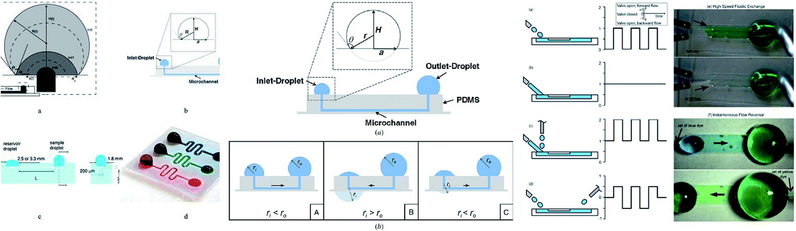 | ||
| Fig. 4 (i) The types of surface-tension-driven passive microfluidics in different studies, which include the recession of a drop in two phases along with a front view and side view of the microfluidic system in passive pumping (this figure has been adapted from ref. 113 with permission from ELSEVIER, copyright: 2018). (ii) A schematic diagram of surface tension driven microfluidics. The flow direction is basically determined by the radius balance of the droplets; the bold arrows in the figures denote the flow direction (this figure has been reproduced from ref. 99 with permission from IOP, copyright: 2008). (iii) Different surface-tension-driven flows: (a) pulsatile forward flow, (b) constant forward flow, (c) constant forward-flow with additional liquid packets, (d) alternating (forward/backward) flow, (e) whole-channel fluidic exchange achieved with alternating constant flow by two nozzles, and (f) instantaneous flow reversal using alternating (forward/backward) flow (this figure has been adapted from ref. 110 with permission from the Royal Society of Chemistry, copyright: 2012). | ||
| S. no | Analytes used | Materials used | Auxiliaries involved | Flow rate | Advantages | Disadvantages | Applications | Ref. no |
|---|---|---|---|---|---|---|---|---|
| 1 | Air and water | PDMS, SU-8 photoresist | 10 μl min−1 | Newtonian and non-Newtonian fluids were handled | A computational model was studied alone | Disposable microfluidic biochips | 90 | |
| 2 | Water | PDMS | Pipette or syringe | 1.25 μl s−1 | Easy interfacing | Evaporation occurs | Small labs and high-throughput assaying systems | 91 |
| 3 | Fluorescent spheres in DI water | PDMS | Pipette | Constant flow rate | Evaporation is a slow process | Biological or chemical application | 92 | |
| 4 | Red and green fluorescent spheres in DI water | PDMS | Pipette | Simple and portable | The mixing process begins only after the merging of liquids | Micro total analysis system | 93 | |
| 5 | Pure oleic acid and water | PDMS moulds with glass | Syringe pump | Reduced use of reagent | Droplet symmetric is corrected only with the asymmetric flow | High-throughput screening | 95 | |
| 6 | Pure methanol | PDMS | 2 ml min−1 | Tough transportation of methanol in a few hours | Small-scale DMFCs for portable electronics | 96 | ||
| 7 | PDMS, SU-8 photoresist | Micropipette | Practically analyzed and long lasting | Increase in the output pressure decreases flow | Cell studies | 97 | ||
| 8 | Cell culture medium with protein | PDMS | Pipette | 34.6 nl s−1 to 16.6 μl s−1 | Highly parallel arrays with 3D cell cultures are employed | Not applicable to high-density valve arrays | Diagnostics and drug development | 98 |
| 9 | Mixture of DI water & fluorescent particles | PDMS | Pipette | Backflow due to flow rotation of outlet liquid | 99 | |||
| 10 | DI water and methanol | PDMS | Pipette | 85 nl s−1 to 196 nl s−1 | Geometrical properties can affect the flow rate | LOC devices | 101 | |
| 11 | DPBS with FITC dextran (culture medium) | PDMS | Pipette | Easily adaptable with high throughput | Gradient generation is affected by fluid viscosity | Biological and drug discovery applications | 100 | |
| 12 | PDMS | Automated fluid delivery system | 4 ml min−1 | No substrate bonding is required | Flow rates are limited by device dimension | Cell culture and biological applications | 102 | |
| 13 | Fluorescent beads | PDMS | Automated fluid delivery system | 4 ml min−1 | No substrate bonding is required | Control of flow direction is difficult | Biological applications, drug-cell studies | 103 |
| 14 | Blood or plasma mixed with glycerol | PDMS | Pipette | Minimal reagent consumption, and waste generation | Drastic decrease in flow rate over time | Immunoassays and LOC | 104 | |
| 15 | Saline | PDMS | Pipette | 2.35 μl min−1 | Particle counting is done within the system | External power source is required for counting | POC or diagnostic MFD | 105 |
| 16 | Normal urine, mammary gland epithelial cells | PDMS | Pipette or automated liquid handling system | Reduced number of cells and reagents are required | Reagents with different viscosity or surface tension should be optimized | Screening in cell culture and biological cell-based assay | 106 | |
| 17 | Neutrophils, tumor cells, stem cell, neurons, and bacterial cells | Glass substrate with PDMS mould | Pipette | Manipulation of fluid flow, and real-time monitoring of the cells | Complicated microfabrication process | Chemotaxis, stem cell differentiation, and endothelial cell migration | 107 | |
| 18 | PDMS | Pipette | Low reagent consumption and easy to fabricate | Low efficiency | Food and remote military operations, home healthcare | 108 | ||
| 19 | PBS with red and green food colorant | PDMS | Pipette | Cell population can be patterned | Mixing of sample | Wound-healing assay | 109 | |
| 20 | Green, yellow and blue dyes | PDMS | 4 ml min−1 | High flow rates are observed | Designing of small channel is tough | Cell-based assays | 110 | |
| 21 | Axon, DI water | PDMS, parylene | Pipette | ∼0.63 μl s−1 | Flexible and user convenient | The same chemical concentration | Axonal guidance studies | 111 |
| 22 | Bone marrow stromal cells | Polymer sheets | Micropipette | Separation of cells is comparatively good | Increased space requirement | Microscale metabolomics | 112 | |
| 23 | Water | Micropumps | 4 ml min−1 | Straight forward implementation of channels | Radii of the droplet vary | Drug delivery and cell biology | 113 |
Pressure-driven
Fluid pressure is a measurement of the force per unit area. Pressure in liquids is equally divided in all directions; therefore, if a force is applied to one point of the liquid, it will be transmitted to all other points within the liquid.114 MFD and LOC devices employing pressure for their passive operations are shown in Fig. 5. In a passive pressure-driven technique, the pressure created in the reservoirs to drive the sample is achieved either by pipetting or by a finger-force pressure.115 Liu et al. reported a twisted microchannel with chaotic advection that possessed high potential mixing even for fluids with a low Reynolds number.116 Ahn et al. suggested the fluid control technique and verified that the low-pressure drop in the fluid tended to maintain the flow without any complicated pumps.117 Also, Jeon et al. described the design and fabrication of passive valves and pumps, which used the pressure-driven mechanism instead of electro-osmotic pumps. The fabrication included aligning, stacking, and bonding of a patterned membrane.118 Rush et al. established a 2D serpentine channel with the flow of low-Reynolds-number Brownian solute particles.119 Later, Moorthy et al. developed an on-chip porous filter that separates minimal volumes of biological fluids in real-time applications and analysis.120 Also, Hu et al. investigated the relationship between the pressure drop in the rough channel and smooth channels and also the pressure drop due to a change in height. It was found that in a rough channel the pressure drop increased and when the channel height increased the pressure drop decreased.121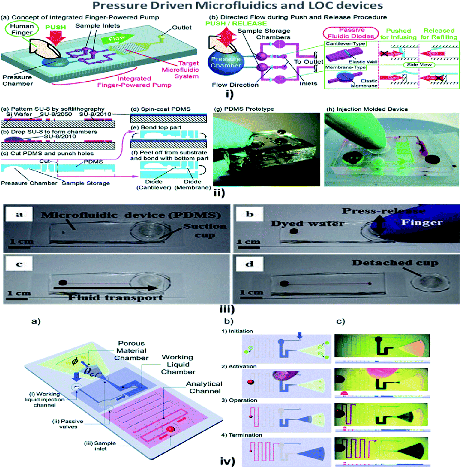 | ||
| Fig. 5 (i) (a) An integrated human-powered pumping system. By pushing the deformable chamber, mechanical pressure infuses the solution from the inlets to the outlets; (i) (b) the pumping procedure of the finger-powered pump with push-and-release actions. (ii) Fabrication via a multilayer soft lithography process; (ii) (a–f) the device consists of three layers of PDMS; (ii) (g) a fabricated PDMS pumping system; (ii) (h) a fabricated prototype via the injection moulding process (figures (i) and (ii) have been adapted from ref. 127 with permission from the Royal Society of Chemistry, copyright: 2014). (iii) Suction-cup-driven equipment-free fluid pumping: (a–d) finger-triggered pumping and reversible integration of the PDMS suction cup to the MFD (figure (iii) has been reproduced from ref. 132 with permission from SPRINGER, copyright: 2018). (iv) A self-powered imbibing microfluidic pump by liquid encapsulation (SIMPLE): (a) sequential pump operation and (b) an experimental presentation. (c) Initially, the chip is prefilled with the working liquid (blue) through the inlet denoted by 25 thick blue arrows and encapsulated by impermeable protective foil patches (green circles). Before activation, the foil is removed, the sample (red) is deposited over the inlet hole, and temporary finger force can activate the pump. When the working liquid touches the paper, the finger can be removed, and the pump is activated. The pump works until the working liquid saturates the paper or until all of the fluid has been sucked into the paper (figure (iv) has been adapted from ref. 129 with permission from the Royal Society of Chemistry, copyright: 2014). | ||
Chen et al. explained that a wavy-wall section incorporated within the microchannel developed a centimetre-long high concentration gradient by increasing the interfacial leads.122 Jiang et al. explained the push or pull in the sample fluid due to a negative or positive pressure that a syringe pump would create.123 Hattori et al. confirmed that fluid flow commenced only when the pressure was applied to the fluid by using a syringe pump or micropipette through an air vent filter.124 In addition, when a finger-powered pressure of about 3–4 kPa was applied at the inlet, sample movement occurred.114 In their investigations, Davey et al. recommended a system where the inlet and the outlet were a hydrophobic and a hydrophilic needle, respectively, and the channel was made of a hydrophilic region where the fluid from the inlet traversed the channel and reached the outlet.125 Tice et al. reported an electrostatic microvalve with passive components embedded in them, which was used to regulate the pressure in hydraulic control lines and actuate pressure-driven components.126
Finger-power integrated pumping systems had been utilized to eradicate the limitations produced by the use of external pumps. Pressure generated inside the pressure chamber played a vital role in determining the efficiency of finger-powered pumps.127 Thus the requirement for pre-evacuation of PDMS devices in a vacuum chamber was eliminated. Thereby, the design of a simple POC pumping method using a single-layer structure where the dead-end microfluidic channel was partly surrounded by an embedded microchamber, with a thin PDMS wall separating the dead-end channel and the embedded microchamber, was reported by Xu et al.128 But the working liquid created a reduced pressure in the analytical channel and induced sequential sample flow into the microfluidic circuits. Kokalj et al. reported simplified activation by fingertip pressure with no external power or control for a wide range of applications in POC diagnostic settings.129 Jeong et al. developed an on-chip microflow control technology with the ability to mimic in vivo conditions at an in vitro microscale for long-term tissue culture with a continuous flow rate. The passive flow was initiated using a siphon effect, and a yarn flow resistor to regulate the flow rate in the microchannel.130 Thanks to implantable drug delivery systems, a micropump for controlled, automated inner-ear drug delivery with the ultimate aim of producing a long-term implantable/wearable delivery system was investigated by Tandon et al.131 Currently accessible pressure-driven approaches in passively driven microfluidics are summarised in Table 2.
| S. no | Analytes used | Materials used | Auxiliaries involved | Flow rate | Advantages | Disadvantages | Applications | Ref. no |
|---|---|---|---|---|---|---|---|---|
| 1 | Sodium hydroxide and ethyl alcohol | PDMS membrane | Syringe pump | Minimum chances of clogging, fouling, and loss of sample | Increased in the complexity of flow | Biochemistry analysis, drug delivery | 116 | |
| 2 | PDMS | 1 μl min−1 | Flow rate can be tailored based on channel height | Low flow rate | Biochemical analysis systems | 117 | ||
| 3 | Plasma | PDMS | Used where the electro-osmotic pumping is not feasible | Miniaturization of Si valves was difficult | Disposable diagnostic and drug screening applications | 118 | ||
| 4 | Incompressible Newtonian fluid | Limited by their total length | 119 | |||||
| 5 | Fluorescent-labeled beads, rabbit blood | Pre-polymer, glass | Pipette | 10 and 20 μl min−1 | Eliminates the need for centrifuging principle | Drug delivery, cell culture | 120 | |
| 6 | Water | Pressure drop in the microchannel in high | LOC | 121 | ||||
| 7 | Incompressible Newtonian liquids | Both active and passive mixing are required | Drug delivery, DNA hybridization | 122 | ||||
| 8 | Microbeads, blood | PDMS | Syringe pump | Inexpensive, fast and sensitive for fluid flow | Difficult to integrate with POC | Immunoassay | 123 | |
| 9 | Water with red-coloured dye | Glass slide | 3–4 kPa pressure alone is required | External pressure is required | POC diagnostics | 114 | ||
| 10 | Viscous liquid | PDMS | Syringe pump | 500 μl min−1 | Highly stable | Detection of air-borne contaminants | 125 | |
| 11 | Culture media | PDMS | Micropipette | Efficient, user-friendly | Drug discovery | 124 | ||
| 12 | Drug of interest | Polyamide | Drug loading pump | 40 μl min−1 | Requires no additional valves to assist the flow | Constant dosage | Cochlear drug delivery system | 133 |
| 13 | Rabbit blood | PDMS, parylene | Microneedle | Simple in vivo blood sampling process | Needs to be operated in pneumatic platforms | Biosensor chip | 126 | |
| 14 | Green-dyed water | 3-Layered PDMS | Pipette | 3.75 times greater than water flow | Transportation of singular fluids is possible | Pressure varies due to the use of different fingers | Point of care and disposable biomedical equipment | 127 |
| 15 | Deionised water | PDMS | Syringe | 0.089 to 4 nl s−1 | Syringe supplies pressure source to drive | POC pumping system | 128 | |
| 16 | Blue and red dyed water | PDMS | Syringe or pipette | 0.07, 0.12 and 0.17 μl s−1 | Combined with the hydrophobic polymer system to stay stable | Speed decreases with filling the channel | Point of care diagnosis | 129 |
| 17 | Endothelial cell (human) | PDMS | Pipette | 10–100 ml h−1 | Physiological levels of flow can be regulated | Dependency on height | Cell-based applications | 130 |
| 18 | Layers of PEI for the rigid structure | Electronic dose control | 13–18 μl min−1 | Increased efficiency within the system | Reduction in system pressure is tough | Hair-cell regeneration therapy | 131![[thin space (1/6-em)]](https://www.rsc.org/images/entities/char_2009.gif) |
|
| 19 | Umbilical vein endothelial cells | PDMS | Pipette | 950 μl min−1 | Easy distribution of pressure | Cell culture in drug discovery and point of care | 134 | |
| 20 | PDMS with oxygen plasma treatment | 1.42 ml min−1 | Constant flow rate under the sinusoidally varying signal is seen | POC diagnostic devices | 135 | |||
| 21 | Microparticle stock solution with DEX | CAD design for channels | Pipette or syringe | 1.55 μl min−1 | Mono-dispersed droplet formation is achieved | Cell analysis, cell-based assays | 136 | |
| 22 | Sterile sputum | PDMS | Micropipette | 4 ml min−1 | High recovery rate of leukocytes | Pulmonary diseases detection | 137 | |
| 23 | Phosphate buffer | PDMS | Syringe pump | 80 μl min−1 | Rapid fluid mixing | Enzyme-based assay | 138 | |
| 24 | Dyed deionized water and mineral oil | PDMS | Pressing and releasing cup | Increasing flow rate | Simple and effective. Fabrication of cup is easy | Diameter of the cup stops the flow | Resource-limited applications | 132 |
| 25 | Glycerol diluted in water | PVC and PMMA | Finger activation | 0.5–150 μl min−1 | Drug delivery applications | 139 | ||
| 26 | Ethyl alcohol, acetone | PDMS | Teflon tube to release air | 30.56–33.98 μl min−1 | Increased flexibility and independent | Immunoassays | 140 |
Satoh et al. in 2016 reported multiple medium-circulation units on a single MFD that were driven only by two pneumatic pressure lines with three independent culture units, in which the cells were cultured under medium circulation flow. The authors stated that pneumatic pressure could be easily distributed to multiple wells in a reservoir with a common gas-phase space without any changes in tube connections.134 Zhang et al. developed a microfluidic passive flow regulator with an in-built five-layer structure valve for high-throughput flow-rate control in microfluidic environments by constructing a gas-driven flow system and analyzed the flow regulation.135 Moon et al. investigated a passive microfluidic flow-focusing method to generate water-in-water aqueous two-phase system (ATPS) droplets without the involvement of any external components. This was the first microfluidic technique that formed low interfacial tension ATPS droplets without applying external perturbations.136 Ryu et al. examined a closed-loop operation of inertial microfluidics, which could dissociate clinical airway secretions and isolate/enrich immune-related cells for in vitro downstream assays. They found their applications in clinical in vitro cell-based biological assays of various pulmonary diseases like acute respiratory distress syndrome, pneumonia, cystic fibrosis and bronchiectasis.137
Lee et al. also developed a negative pressure-driven fluid flow generated by a simple finger-triggered operation where the PDMS suction cup was placed at the outlet of the device and dispensed the fluid at the inlet.132 A new infusion-based simple method (ISIMPLE) for drug delivery into the skin was developed by Dosso et al. with a self-contained skin patch without any external driving source, where the expelled air increased the pressure due to the extreme flexibility of the design and manufacture. The ISIMPLE concept offered enormous opportunities for entirely autonomous, portable, and cost-effective LOC devices.139 Later, Liu et al. developed a PDMS pump that utilized the air released from the aerated PDMS to create a positive pressure in the MFD.140
Osmosis
Osmosis is the spontaneous net movement of solvent molecules to a region of higher solute concentration in the direction that tends to equalize the solute concentrations on both sides through a selectively permeable membrane. Permeability depends on solubility, charge, or chemistry, and solute size. Water molecules diffuse through the solute from the solvent layer.142 Bruhn et al. demonstrated the development of devices that are capable of pressure generation based on the osmosis principle, which could be made from available low-cost materials.143 Some MFD and LOC devices using osmosis as a passive approach for their operation are shown in Fig. 6.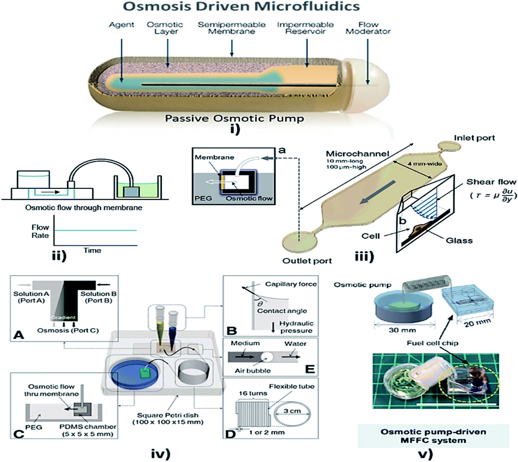 | ||
| Fig. 6 (i) Osmotic pump schematic diagram (this figure has been adapted from ref. 147 with permission from the Royal Society of Chemistry, copyright: 2009). (ii) Osmotic pump operation (this figure has been reproduced from ref. 57 with permission from Wiley, copyright: 2014). (iii) An operational diagram of the system, including the pump unit and the Poiseuille flow with constant wall shear stress (this figure has been adapted from ref. 148 with permission from IOS Press, copyright: 2010). (iv) Experimental setup with four components, namely concentration gradient, pipette tips, osmotic pumps and coiled tube (this figure has been reproduced from ref. 146 with permission from Alpha Med Press, copyright: 2009). (v) A microfluidic fuel cell (MFFC) system using an osmotic pump (this figure has been adapted from ref. 149 with permission from IOP, copyright: 2018). | ||
Later, Good et al. integrated and analyzed a polymeric microfluidic device in a portable mechanical micro-pumping system that used fluid-responsive polymer particles as an actuator, without external power.144 In 2009, Xu et al. reported that, when a semi-permeable membrane was sandwiched between the inner osmotic reagent chamber and the outer water chamber, the water flow to the osmotic reagent chamber via the semi-permeable membrane facilitated the flow of fluid in the channel by the process of osmosis.145 Furthermore, stable concentration gradients are required for cell analysis and culture. The development of a microfluidic platform provided stable concentration gradients for cells of various signaling molecules for more than a week with only the least amount of handling and no external power source. Later, Park et al. optimized the osmotic pumping performance by balancing the capillary action and hydraulic pressure in the inlet reagent reservoirs.146 Updates on osmotic-driven passive pumping techniques in microfluidics are summarised in Table 3.
| S. no | Analytes used | Materials used | Auxiliaries involved | Flow rate | Advantages | Disadvantages | Applications | Ref. no |
|---|---|---|---|---|---|---|---|---|
| 1 | Sieved particles | PDMS and natural rubber | Dropper | 17 μl min−1 | Can be placed directly on a microdevice | Reactivation of pump requires water | Finds the application in portable devices | 144 |
| 2 | PDMS chamber | Syringe | 0.33 μl min−1 | Low flow rate is used for constant refreshing of culture medium | Regular refreshing of osmotic reagent | Microfluidic flow injection system | 145 | |
| 3 | Cholera toxin subunit B | PDMS cubic chambers | Micro-pipette | 0.15 μl h−1 | Provides the concentration gradient for more than a week | Low flow rate | Basic and translational research areas such as stem cell differentiation research and long-term cell culture | 146 |
Capillary
Capillary action is defined as the movement of a fluid within the spaces of a porous material due to the intermolecular forces between the liquid and the surrounding solid surfaces that enables the liquid to flow in narrow spaces without the assistance of, or even in opposition to, external forces like gravity.87Juncker et al. reported a capillary pump assisted capillary flow microfluidic system, where the flow was activated from the open and closed channels of the device.151 MFD and LOC devices incorporating the capillary technique are shown in Fig. 7. Simultaneously, a microfluidic capillary system was presented for the continuous transport of fluid using capillary force, when the fluid was placed in the service port.151 Mixing of fluids is necessary for drug delivery and research. So, Hosokawa et al. reported an MFD which used capillary force for pumping.152 To avoid clogging by fluids, Kim et al. presented a capillary passive retarding microvalve at the junction of the microfluidic channel where the propagation occurred only after the merging of two fluids.153 An exact discussion of interface motion driven by capillary action in a microchannel was reported by Ichikawa et al. where a dimensionless variable of the driving force was used to predict the interface motion.154 In order to maintain and control the flow properties of capillary systems (CSs), Zimmermann et al. developed a design for capillary pumps. These capillary pumps were designed to have a small flow resistance and were preceded by a constricted microchannel, which caused flow resistance.155 Subsequently, Suk et al. developed a technique to control the autonomous capillary flow with a passive method where the flow could be retarded with appropriate hydrophobic patterns in hydrophilic channel surfaces. The microfluidic system was designed in such a way that it contained two planar parallel surfaces, separated by spacers.156
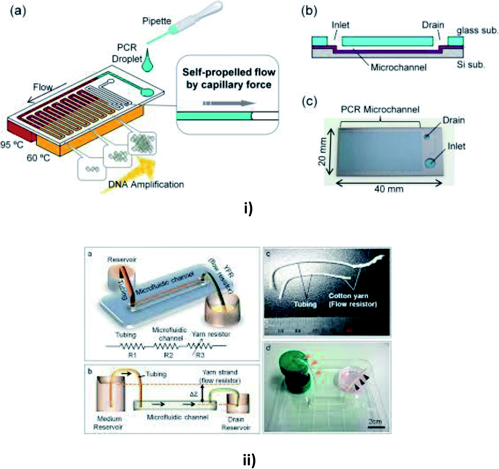 | ||
| Fig. 7 (i) Schematic diagrams of a microfluidic device for self-propelled continuous-flow PCR: (a) concept diagram; (b) a cross-sectional view of the microfluidic device. (c) A photograph of the fabricated microfluidic device (this figure has been reproduced from ref. 182 with permission from Elsevier, copyright: 2015). (ii) A yarn flow resistance (YFR)-regulated microflow control system: (a) a schematic diagram showing the siphon effects in the yarn-capillary-resistance-driven micropump system; (b) a schematic diagram of the water-head-difference-driven siphon effect controlled by the YFR; (c) a photographic image of a yarn capillary regulator; (d) the microfluidic device prepared with a YFR (this figure has been adapted from ref. 130 with permission from the Royal Society of Chemistry, copyright: 2014). | ||
Flow rates may vary in different substrates, so Zhu et al. reported a study of capillary flow rate in several substances, including glass, polycarbonate (PC) and polydimethylsiloxane (PDMS) to measure the contact angles and to examine the longevity of capillary flow in PDMS and PC chips to give better clarity in measuring the flow rates.157 Lynn et al. realized a pressure difference arising from the small curved meniscus at the bottom of the outlet reservoir that drove the fluid with a constant fluid flow for more than an hour.158 Later, Gervais et al. described the fluid flow from high capillary pressure to low capillary pressure and increased the channel width at each level to reduce the friction, thereby leading to a high flow rate.159 Mukhopadhyay et al. proposed a microchannel bend in polymethylmethacrylate (PMMA) of different widths. The effects of channel aspect ratio and different separation angles were studied for fluid flow.160 Eventually, Alphonsus et al. explained in a short review on microfluidic immunoassay that the capillary pressure in the channel pushed the sample, causing the fluid to flow within the device.161 Kim et al. realized that the surfactant-added PDMS could be used to increase the hydrophobicity of PDMS to increase the filling rate of blood by capillary action.162 Souza et al. fabricated a toner-based microfluidic device in which the fluid flowed towards the outlet as soon as the serum was placed in the sample inlet.163 Later, Horiuchi et al. also developed an immunoassay chip which consisted of vertically integrated capillary tubes to create negative pressure and pump the fluid towards it.164 Once the fluid had been placed in the inlet well, Kim et al. verified the flow timing control and direction of multiple solutions in the channel.165
Kistrup et al. reported aspects of using rapid prototyping instead of pilot (mass) production. They included the fabrication of the microfluidic system that employed injection moulding and ultrasonic welding in which the fluid flow was assisted by the capillary pressure at the interface nozzle.166 Berthier et al. proposed the onset of the suspended capillary flows (SCF) and the viscous friction at the walls using the force balance between the capillary forces that drove the flow.167 Plasma separation is possible in passive pumping microfluidic technology. Madadi et al. demonstrated a self-driven blood plasma separation microfluidic chip, which was capable of extracting more than 0.1 μl of plasma from a single droplet of undiluted fresh human blood (5 μl) with high purity without any external pumps.168 Nie et al. reported a flexible microfluidic device that filled the channel through capillary force to provide continuous fluid pumping through an evaporation micropump. The hexagonal arrangement at the pore array drove the fluid flow and automatically absorbed liquid through a filter paper interface.169 Mukhopadhyay et al. described a leakage-free PMMA fabricated MFD with microchannel bends with the effect of surface wettability on surface-driven capillary flow. This type of microfluidic system was utilized in blood cell separation from whole blood.170 Maxime Huet et al. developed and integrated a biological protocol to observe RBC's agglutination in POC analysis. This work proved that the agglutination of blood began directly within the chip containing embedded reagents where a correlation-based indicator was used to conserve both spatial information and image quality.171 Later, Bunge et al. reviewed the utilization of symmetrical surface phase guides (SSPG), where the wall-less channels were generated by patterning hydrophobic phase guides on both sides of the chip to induce liquid propagation with the help of the capillary effect.172 Wu et al. generated flow-focusing droplets through the capillary effect to reduce the requirements of subsequent systems in addition to high flexibility.173
Zhai et al. developed a microfluidic device, which was insensitive to backflow due to the integration of a syringe pump to balance the capillary pressure within the channel.174 A study on the microfluidic self-flowing chip to understand the influence of micro-scale topographies was reported by Xie et al. According to this work, the flow rate increased with increasing gradient on the surface and the flow speed was 40 times greater with high efficiency.175 Vasilakis et al. reviewed a simple high-speed filling passive capillary pump integrated with lab-on-printed circuit board technology (Lo-PCB), with induced capillary pressure to produce stable flow rates.176 Akyazi et al. developed a new concept for fluid flow manipulation in micro paper-based analytical devices (PADs), where the ionogel (considered to be a negative passive pump) could drive fluids by the swelling effect, which controlled the flow direction and volume to the outlet.177 Frimat et al. described a new single-cell trapping procedure within the micro sieve electrode array (SEA) through capillary phenomena for an organized positioning of neurons to produce higher biocompatibility.178
Mei et al. developed a capillary-based open microfluidic device (COMD) for monodispersed droplet generation, from gas bubbles to highly viscous polymer solutions to provide high throughput in industrial emulsification. Capillary action was used as a portable sidewall of another microchannel with controllable size.179 Kim et al. described a liquid additive, which passively controlled the velocity of cells within a detectable range during capillary sample loading, thereby eliminating the need for bulky and expensive pumping equipment. It also required the adoption of an immune bead assay, which was quantified with a portable fluorescence cell counter based on a blue-light-emitting diode.180 Moonen et al. investigated capillary-based passive pumping for optimized neuronal cell trapping across a microsieve with gentle velocity profiles and high survival rates.181 Reports on capillary-based passive pumping in microfluidics are summarised in Table 4.
| S. no | Analytes used | Materials used | Auxiliaries involved | Flow rate | Advantages | Disadvantages | Applications | Ref. no |
|---|---|---|---|---|---|---|---|---|
| 1 | Bovine serum albumin | Flat PDMS | Pipette | 220 nl s−1 | Free from dead volumes | Flow rate quickly reduces | Portable diagnostics, biological assays | 151 |
| 2 | Fluorescein ethanol | PDMS and glass surfaces | Syringe | Simple hardware setup and easy to operate | Depends on the contact angle for sample loading | Biological or chemical analysis | 152 | |
| 3 | Deionised water | PDMS | Pipette | Clogging at the confluence is prevented | Liquid propagation is done only after the emergence | 153 | ||
| 4 | Ethanol | PDMS and Pyrex glass tube | Syringe | Interface motion can be predicted easily | Assumption of a constant value | Disposable on-site diagnostic system | 154 | |
| 5 | Food colorant | PDMS | Pipette | 0.2–3.7 nl s−1 | Controlled manner of filling to prevent the collapse | Presence of the resistance | Bioanalytics | 155 |
| 6 | Distilled water | PDMS | Pipette | Controls the speed of the autonomous capillary flow | Experiments were entirely done on distilled water | Total analysis systems or LOCs | 156 | |
| 7 | PDMS and PC chips | Longevity is achieved | PC and PDMS chips were made by air plasma treatment | 157 | ||||
| 8 | PDMS with glass slides | 1 μl min−1 | Constant flow rate for more than an hour | LOC devices | 158 | |||
| 9 | Human serum with CRP | PDMS and glass | Pipette | 82 nl min−1 | Different interface shapes in the PDMS channels | Presence of Laplace pressure stops the flow | Detection of c-reactive protein (CRP) | 159 |
| 10 | Dyed water | PDMS and PMMA | Highly efficient for particle separation | Different channel size is required for different particle filtration | Blood filtration, LOC system | 160 | ||
| 11 | PDMS | Automated liquid handling systems | Reduce cost and reagent supply | 161 | ||||
| 12 | Blood | PDMS material | Simple to use, flexible and robust | Only about 20 nl of plasma is extracted | POC diagnosis | 162 | ||
| 13 | Cellulose powder | PDMS and glass surfaces | Pipette | Detection of glucose, protein, and cholesterol | Poor device-to-device reproducibility | Bioanalytical applications or POC diagnostics | 163 | |
| 14 | Milk sample | Acrylic resin | Pipette | 60 and 110 μl s−1 | Refill without drying the center channel | Decreased sensitivity | Food analysis and drug discovery | 164 |
| 15 | Bovine serum albumin | PDMS | Pipette | Device to device repeatability is well defined | Pressure prediction at each step is required | Biochemical assays and immunoassays | 165 | |
| 16 | PDMS | Due to the rotational speed | Does not require surface treatment | POC diagnosis | 183 | |||
| 17 | Blood | PDMS mould | Injection moulded | Mostly unidirectional | Error comes from the milling process | Point of care | 166 | |
| 18 | PMMA plate | Pipette or micro-needle | Capillary motion of the blood is monitored | Increase in viscosity when velocity decreases | POC diagnosis and home care systems | 167 | ||
| 19 | Blood | PDMS | Micro-pipette | Increased amount of extracted plasma | Numerous valves are required | POC diagnostics | 168 | |
| 20 | Plasma | PDMS | Sweat | 7.3 × 10⁻³ to 1.2 × 10⁻¹ μl min−1 | Prolonged flow due to evaporation | Leads to local flow near the inlet | Wearable sweat-sensing device | 169 |
| 21 | Dyed water | PDMS and PMMA | Syringe pump | Separation time is lower | Bend region and the bend angle should be maintained properly | Bioengineering applications and point of care | 170 | |
| 22 | Blood | Injection-moulded chip made of COP | Micro-needle | Prevents accidental blood projections induced by forced flow actuation | Leakage can occur based on the substrate materials | Used in haemeagglutination | 171 | |
| 23 | PDMS | Syringe pump | 1.2 ml min−1 | Increased stability with a large interface area | Very expensive | Used in the creation of wall-less channels | 172 | |
| 24 | Water in oil | PDMS | Solvent delivery systems | 3 to 60 μl min−1 | Flexible manipulation of droplets within the channels | Instability of the droplets that are generated | Drug delivery systems | 173 |
| 25 | Microbeads | PDMS | Syringe-assisted vacuum pumping | Decreased backflow is observed | Non-Newtonian samples do not give a proper assessment | POC or LOC testing applications | 174 | |
| 26 | PDMS | Injector | 0.865 μl s−1 | Increase in height increases the self-flowing speed within the channel | Decreased flow due to the rough surface | POC or LOC testing applications | 175 | |
| 27 | Red dye in deionized water | PCB fabricated chip | Pipette | 138 μl min−1 | Low-cost, electronic-based disposable analytical platforms | POC diagnosis and LOC equipment | 176 | |
| 28 | Acrylamide | Micropads | Syringe pump | Robust in nature | Energy, electronics, medicine, food or cosmetics | 177 | ||
| 29 | Neuronal cells | 3D micropores | Syringe pump | 2–2.5 μl min−1 | Compactable to microscope focusing used in optical tracking | Flow speed cannot be tightly controlled | Brain-on-a-chip | 178 |
| 30 | Mineral oil, silicone oil | Syringe pump | 0.005 μl min−1 | Flexible and reliable, providing possibilities for mono-dispersed droplet-based studies | Presence of viscous and shearing forces | Cell encapsulation and protein crystallization | 179 | |
| 31 | Streptavidin-coated fluorescent particles | PVP | Pipette | Three-dimensional cell focusing and on-chip cell sorting | Combines multiple features for analyses | Diagnosing and monitoring clinical conditions | 180 | |
| 32 | Neuronal cells | PDMS or glass of choice | Pipette | UV-curable alternative material for low-cost microfluidic chip applications | Tougher analysis of human neural network | Cell capture and cell culture application | 181 |
Gravity-driven flow
This is a technique in which the fluid flow is driven or assisted by the earth's gravity, depending on the viscosity of the fluid and the height of the inlet from the surface. A comfortable and straightforward analysis of the flow rate in the MFD can be determined with the help of the gravity-driven flow principles which accelerate the passive pumping system was reported by Mäki et al. in 2014.185 The microfluidics and LOC devices utilizing the gravity for their passive operations are shown in Fig. 8.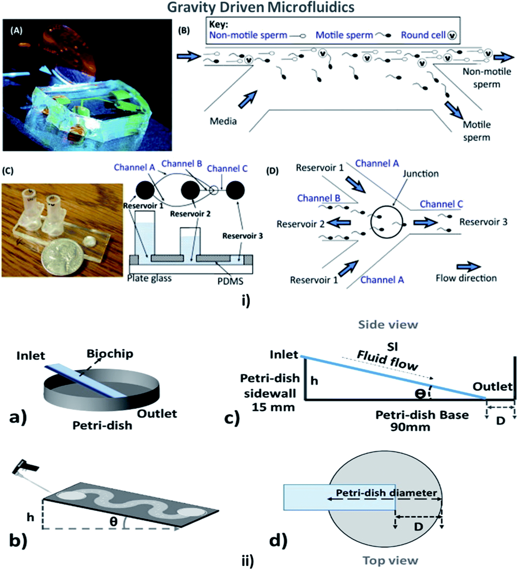 | ||
| Fig. 8 (i) (A) A compact, simple, and disposable device for passively driven sperm sorting; (B) fluid flow used to sort sperm based on their ability to cross the passively driven laminar fluid stream created by a hydrostatic pressure difference between the inlet and outlet (this figure has been adapted from ref. 186 with permission from ACS Publications, copyright: 2003). (C) A compact, passively driven microfluidic device with a side-view and top-view schematic diagram of the generation of hydrostatic pressure differences (this figure has been adapted from ref. 198 with permission from Springer, copyright: 2007). (D) The junction showing sperm movement from an input (reservoir 2) to an outlet (reservoir 3) (this figure has been reproduced from ref. 199 with permission from ELSEVIER, copyright: 2015). (ii) (a, b) Illustrations of pipette Petri dish single-cell trapping (PP-SCT) or tilt microfluidic trapping; (c, d) the side and top view, respectively, where θ is the tilt angle, h is the height of the inlet, D is the distance between the biochip outlet side edge to the Petri dish wall along the diameter, and Sl is the glass slide length (this figure has been adapted from ref. 196 with permission from MDPI, copyright: 2018). | ||
In 2003, Cho et al. described a simple disposable polymeric microscale integrated sperm sorter (MISS) to isolate sperm from semen, which was unattainable by traditional sperm-sorting methods.186 Similarly, Suh et al. explained the purpose of obtaining the motile sperm through gravity-driven flow with increased morphology from normal semen.187 Not only sperm but blood cells could be counted using a gravity-driven MFD that was fabricated using UV laser ablation and resin film lamination by Yamada et al. In 2005.188 Huh et al. developed a unique combination of a simple, self-contained microfabricated device using field-driven separation with micro-hydrodynamics-assisted separation, where the earth's gravity was used to drive the fluids across the channel to assist in separation.189 For cell culture, Lee et al. designed a compatible passive gravity-driven MFD with long-term continuous cell culture perfusion, which was adapted from the standard 96-well plate format to remove tubing and connectors.190
In 2010, Zhang et al. presented a gravity-actuated technique where an oil phase was loaded into the infusion set and then the water phase was pumped into the PTFE (polytetrafluoroethylene) tubing by the gravity of the oil phase.191 Thereby, Sung et al. developed a gravity-induced-flow MFD to provide long-term flow by eliminating the bubble formation based on the mathematical PK-PD (pharmacokinetic/pharmacodynamic) model.192 Abaci et al. in 2014 developed a pumpless recirculating gravity-driven human skin equivalent (HSE)-on-a-chip platform that was simple to fabricate, handle and operate when placed on a rocking platform.22 A way of inducing fluid flow, by elevating the inlet of the channel against gravity by placing it on a rocking platform was demonstrated by Esch et al. in 2015.193 A compactly configured differential flow resistance microfluidic single-cell trapping device with a shorter flow path was introduced and demonstrated by Jin et al. to increase the speed and throughput (in both mathematical and numerical simulations).194 James et al. developed an MFD with efficient trapping of single cells through hydrodynamic flow by positioning the microwells along the flow path, which acted as a mechanical barrier. The hydrodynamic flow inside the channel was analyzed with Comsol Multiphysics with different boundary conditions for varying particle sizes.195 Simultaneously, Narayanamurthy et al. described the rate of single-cell trapping based on the shape of the channel in a passive biochip and concluded that hexagonally positioned microwells possessed high single-cell capture (SCC) percentages. The SCC potential of microfluidic biochips was found to be an improvement over straight channels, branched channels, or serpentine channels. Multiple cell capture (MCC) began to decrease from the straight channel, branched channel, or serpentine channels.196 Kim et al. presented a design for gravity-driven microfluidic systems that could generate self-switching pulsatile flows to mimic physiological blood flow pulsing.197 Comprehensive developments in gravity-based passive pumping in microfluidics are summarised in Table 5.
| S. no | Analytes used | Materials used | Auxiliaries involved | Flow rate | Advantages | Disadvantages | Applications | Ref. no |
|---|---|---|---|---|---|---|---|---|
| 1 | Semen | PDMS | 0.008 μl s−1 | Readily fabricated device | Very low flow rate | Vitro fertilization procedures | 186 | |
| 2 | Semen | PDMS, glass | Pipette | ∼20 ± 40 μl h−1 | Inexpensive, portable, easy to use, and disposable | Does not isolate every motile sperm effectively | Chemical and biological analysis, immunoassay | 187 |
| 3 | Blood, physiological salt solution | Silicon laminated with resin | Pipette, syringe | One-stroke fabrication of grooves for channels | Combining the laminar flows at the microchannel is difficult | Biology and molecular genetics | 188 | |
| 4 | Fluorescein dissolved in BSA solution | PDMS | Tubing | 1 ml h−1 | Continuous particle separation is achieved | Increasing the flow rate will lead to low purity separation for a larger drop | Ultrasound imaging | 189 |
| 5 | DMEM with no drug | PDMS, glass | Pipette | 50 μl per day | Multiple culture plates can be incubated | Requires specialized equipment for cell loading | Cell-based screening, cytotoxicity assay | 190 |
| 6 | Blood and lysing buffer | PMMA | Efficient lysis of RBC with simple structure | Cellular debris cleaning should be done constantly | Clinical genetics, diagnostics | 200 | ||
| 7 | Dimethyl silicone oil | PDMS | Turntable and infusion set | Droplet generation, transport, collision, fusion, mixing, and stopping are possible | Hard to generate droplets for a long period | Cell research and high-content drug screening | 191 | |
| 8 | Cell culture medium | Multilayers of PDMS | Prevents formation of air bubbles, up to 3 days of operation | Nutrient depletion and accumulation of waste affects the viability of cells | Prediction of drug toxicity, cell culture | 192 | ||
| 9 | DMEM with 10% FBS | PDMS membrane | Injection | Long-term maintenance of HSEs for drug testing purposes | Unstable flow rate with decreasing reservoir volume | Skin drug testing studies | 22 | |
| 10 | 650 μl min−1 | Evaluate drugs under fluidic cell culture conditions | 193 | |||||
| 11 | Human cervical carcinoma and embryonic kidney cells | PDMS | Pipette | 375 μl min−1 | Highly beneficial as the rare cells are trapped | Non-uniform distributions of fluidic velocities and pressure drops | Signalling pathway activation, and inhibition (in SCA) | 194 |
| 12 | Water | Increased particle trapping on using a serpentine channel | Single-cell trapping based on the interest | 195 | ||||
| 13 | Motile and non-motile sperm, water | PDMS, glass | Syringe | Highly compatible | Flow is dependent on the difference in height of the source reservoir | Cell culture | 197 | |
| 14 | Trypan blue and lung cancer cells (A549) | Glass substrate | Mechanical obstacles | 0.25–4 ml s−1 | Highly efficient single-cell trapping | Area density of single-cell arrays are reduced | Genomics, proteomics, secretomics | 196 |
Hydrostatic pressure
Hydrostatic pressure is the force exerted by a fluid at equilibrium at a given point acting with equal magnitude in all directions, due to the force of gravity. Hydrostatic pressure increases in proportion to the depth measured from the surface because of the increasing weight of the fluid, exerting a downward force from above.201Weigl et al. presented hydrostatic pressure-driven microfluidic elements, including mixers, valves, and detectors that were employed in ultra-low-cost disposable qualitative and semi-quantitative medical and environmental assays for the home, office, and field use, and for sample or reagent preparation tools to provide processed liquids for downstream analysis.202 Subsequently, a microfluidic cartridge was planned for the extraction of small molecules by the hydrostatic pressure from the mixture of small and large molecules.203 For the culture medium, Marimuthu et al. developed a pumpless perfusion microfluidic chip that could deliver a constant flow rate with reduced pressure due to the intravenous (IV) setup used at the inlet, over the siphon-based gravity-driven microfluidics.204 Later, Seo et al. employed hydrostatic pressure to sort motile sperms of three species, namely bull, mouse, and human, with an average sorting rate.198 The culturing of mouse testis tissue and spermatogenesis in a hydrostatic pressure environment were developed by Komeya et al. In addition, researchers used a resistance circuit to induce slow and long-lasting medium flow in the channel.205 MFD and LOC devices employing hydrostatic pressure for their passive operations are shown in Fig. 9. Comprehensive reports on the hydrostatic pressure-driven passive pumping technique in microfluidics are summarised in Table 6.
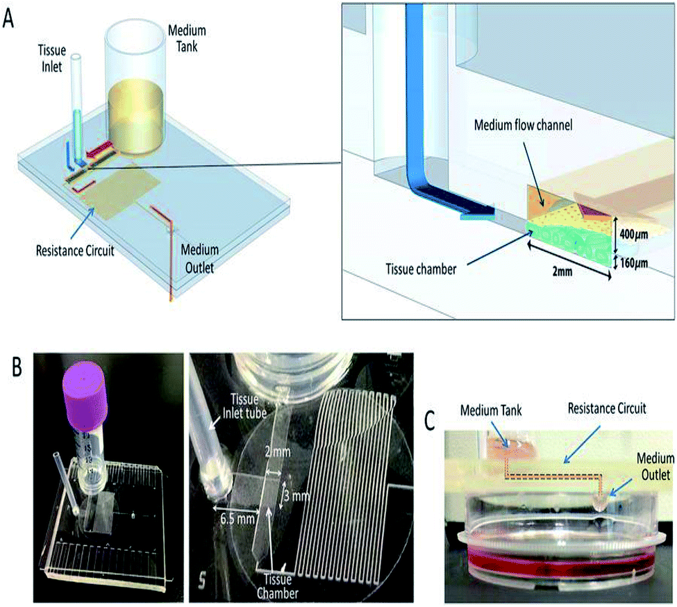 | ||
| Fig. 9 A pumpless MFD. (A) A schematic 3-D image of the PL MFD, showing the sample tank, tissue inlet, resistance circuit, and sample outlet, and an enlarged view of the portion encompassing the tissue chamber. (B) Pictures of the device. On the right, a closer view of the tissue chamber and resistance circuit. (C) A low-lateral view of the device demonstrating the medium-flow route, finally dropping down to the collecting dish (this figure has been reproduced from ref. 205 with permission from Springer, copyright: 2017). | ||
| S. no | Analytes used | Materials used | Auxiliaries involved | Flow rate | Advantages | Disadvantages | Applications | Ref. no |
|---|---|---|---|---|---|---|---|---|
| 1 | Indicator dye with blood | Micropipette or syringe | 99 nl s−1 | Low cost, portable | Equilibrium constant affects the flow rate | Blood plasma separations, blood typing, qualitative immunoassays | 202 | |
| 2 | DNA sample, blood | Plastic | Prediction for high-viscosity solutions is difficult | Drug discovery, toxicology | 203 | |||
| 3 | Human dermal fibroblast neonatal cells | Silicon tubing and syringe | 0.1–10 ml min−1 | Constant flow rate is achieved | Can control only a slow perfusion rate and not suitable for all cells | Development of artificial skin and long-term cell-culture | 204 | |
| 4 | Sperm with phosphate buffered solution | PDMS | Self-movement | Alignment and orientation of the sperm is possible | Height change in the reservoirs disturbs the fluid flow | Clinical labs | 198 | |
| 5 | Mouse testis tissue | PDMS | Micropipette | 0.05 μl min−1 | Constant flow rate for a long range is observed | Tissue culture and organ culture | 205 |
Vacuum driven
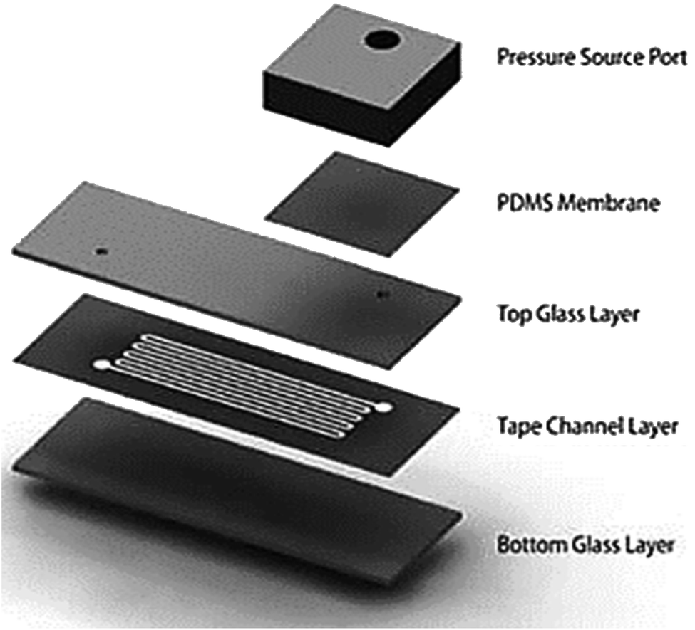
A vacuum refers to any space in which the pressure is lower than atmospheric pressure (negative pressure). Vacuum-driven devices use the ability of an MFD to suck the sample through negative pressure without any extra on/off-chip microfluidic units. Low vapour pressure and degassing become essential when the vacuum pressure falls below this vapour pressure. Degassing is the process of removal of any gas in the channel through permeability or solubility within the membrane to generate a vacuum.206 Song et al. worked to produce a better demonstration of vacuum degassed flow in POC applications using a PDMS-based material, coated with Parylene C.207Later, Monahan et al. developed a channel outgassing technique, where the channel was evacuated, and the negative pressure generated inside the channel assisted the flow with 90% efficiency in eliminating bubble formation.208 A new power-free pumping method for PDMS MFD was developed by Hosokawa et al. to overcome a significant issue in the detection of gold nanoparticle DNA analysis.75 Subsequently, they presented an on-chip heterogeneous immunoassay with a simple structure and operational procedure. Redissolution through the microchannel walls developed the capacity to drive the solution movement and prevent air bubble trapping.209 Dimov et al. reported a microfluidic blood analysis system where the plasma was separated by trapping the RBC and WBC in a trench, and the inlet fluid was pumped due to the suction of the chamber, as a result of pre-evacuating the channel.210 Liang et al. developed a degassed channel with negative pressure to pump the fluid irrespective of the surface tension of the fluid. Before sample loading, channel geometry, surface area, PDMS thickness, exposure area, vacuum degassing time, and post-vacuum idle time when the device was exposed to atmospheric conditions were inspected.211 Eventually, Li et al. designed a PDMS modular pump in a vacuum desiccator with high flexibility and reduced fabrication complexity to create negative pressure in the channel for sample movement.212
Furthermore, Li et al. developed a self-powered one-touch finger-press-activated blood extraction system based on the negative pressure-driven force developed in the pre-vacuum actuator.213 Xu et al. designed a vacuum-driven power-free MFD that depended on the gas solubility or permeability of PDMS that restored the air inside it and encouraged the transfer of air into a vacuum.214 Also, Li et al. worked on the development of a self-powered PDMS-based microfluidic droplet generator with mono-dispersed droplet generation and multi-sample introduction in a controlled way.215 A simplified and inexpensive passive microfluidic channel with excellent analytical performance to carry out microflow injection analysis (mFIA) was investigated by Agustini et al.216 Subsequently, Liu et al. developed a paraffin wax and glass MFD through higher driving pressure to maintain longer working times where the inlet was exposed to air with a slower decline in flow rate.217 Li et al. proposed a high-pressure MFD to drive the fluid using gas permeation and suppressing the generation of bubbles under high temperatures.218 Then, a power-free and self-contained fluid reactor array that performed parallel fluid loading, metering and mixing through pre-degassed PDMS and the change in capillary force due to sudden narrowing of the channel cross-section was developed by Liu et al.219
 | ||
| Fig. 10 A hybrid PDMS utilizing permeability and capillary effects for fluid flow (this figure has been reproduced from ref. 225 with permission from IOP, copyright: 2009). | ||
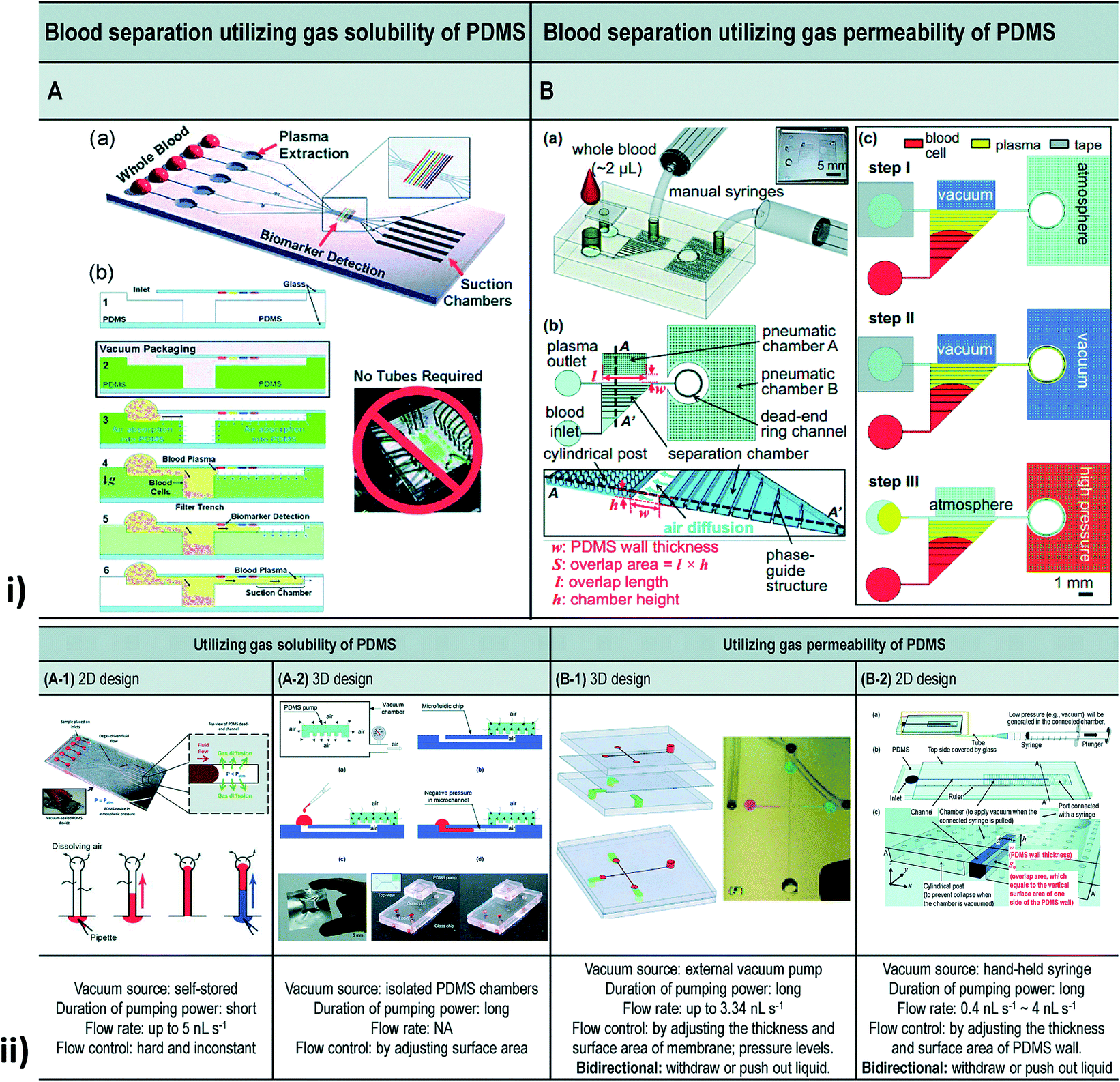 | ||
| Fig. 11 (i) Blood separation utilizing gas solubility and the permeability of PDMS. [A] Self-priming, self-contained, tether-free SIMBAS. [B] Schematic diagrams of the proposed device. (B-a) An overview of the experimental setup using the proposed device. The top layer is a PDMS cover with an inlet and a tape-sealed outlet, and is bonded irreversibly with a bottom fluidic layer. (B-b) A top view and cross-section view. The separation chamber is divided into ten segments of equal volumes by nine phase guides at the bottom. Cylindrical posts are used to prevent the collapse of the pneumatic chamber when it is evacuated by the manual syringes. w and S stand for the PDMS wall thickness and the overlap area between the pneumatic chamber A and the separation chamber, respectively. The overlap area (S), where the flux of air diffuses, is calculated from the overlap length (l) multiplied by the chamber height (h). Drawings are not to scale. (B-c) Experimental steps. (ii) Different types of vacuum-driven power-free micro-pumping methods utilizing the gas solubility or permeability of PDMS. (A-1) A 2D micro-pumping design utilizing the gas solubility of PDMS. A whole PDMS device is pre-evacuated in a vacuum environment. (A-2) A 3D micro-pumping design utilizing the gas solubility of PDMS. A PDMS slab is pre-evacuated in a vacuum environment. See also Fig. 1A. (B-1) A 3D micro-pumping design utilizing the gas permeability of PDMS. External vacuum pumps are connected to the ports in the control channels. (B-2) A 2D micro-pumping design utilizing the gas permeability of PDMS. A hand-held syringe can generate a vacuum environment (figures (i) and (ii) have been adapted from ref. 214 with permission from the Royal Society of Chemistry, copyright: 2015). | ||
| Sl. no | Analytes used | Materials used | Auxiliaries involved | Flow rate | Mechanisms used | Advantages | Disadvantages | Applications | Ref. no |
|---|---|---|---|---|---|---|---|---|---|
| 1 | Aqueous fluorescent buffers spiked with fluorescein | PDMS | Syringe | Degassed driven flow | Efficient at eliminating air bubbles | Channel networks are complex in construction | 208 | ||
| 2 | Fluorescent particle solution diluted with deionized water | PDMS | Micropipette | 0.5–2 nl s−1 | Degassed driven flow | Efficient deposition and two analyses can be conducted on both sides | Not suitable for continuous operations | Point-of-care, single-use analytical devices | 75 |
| 3 | Human serum enriched with CRP | PDMS with SU-8 photoresist and glass | Pipette | 3–5 nl s−1 | Degassed driven flow | Fast assay time is achieved | Usage of deionized water for dilution | Solution mixing and electrophoresis | 209 |
| 4 | Blood | PDMS | 0.5–2 nl min−1 | Degassed driven flow | Blood analysis is computed within 10 minutes | Evacuation of the channel is necessary | POC diagnosis | 210 | |
| 5 | Blue food colouring dye | PDMS placed on glass slides | Micropipette | 0.2 to 3 nl s−1 | Degassed driven flow | Degassing time is very high | Lab-on-a-chip devices | 211 | |
| 6 | Food dye solution | PDMS | PDMS pump slab, micropipette | Degassed driven flow | Pump slab must be evacuated overnight | LOC devices and point-of-care diagnostic | 212 | ||
| 7 | Blood (rabbit) | PDMS | Micro-needle | Degassed driven flow | Point-of-care diagnosis | 213 | |||
| 8 | Bovine serum | PDMS | Sequential injection | Degassed driven flow | No need for surface treatment | Pumping power decreases at a faster rate | Point-of-care diagnosis | 214 | |
| 9 | Plastic pipette tips | Degassed driven flow | Self-powered and portable for easy convenience | Fluctuation of the flow rate is seen | Droplet-based applications in in-field analysis | 215 | |||
| 10 | Cotton threads | Injection moulded | 2.2 ± 0.1 μl s−1 | Degassed driven flow | Simple, fast, cheap and reliable in their application | Loss of samples remains unavoidable | 216 | ||
| 11 | Food dye solution | PDMS, glass substrate | 0.92 μl min−1 | Degassed driven flow | Longer pumping duration towards the outlet | Immediate decay is possible due to diffusion | Applications with longer working period | 217 | |
| 12 | Aqueous/oil microdroplet | PDMS | Pipette | 250 μl h−1 | Degassed driven flow | Dramatic improvement of pumping performance | Bubble generation is observed under vacuum desiccators | Autonomous microdroplet-generation/transport and biometrics | 218 |
| 13 | Dye | PDMS | Pipette | Degassed driven flow | Inexpensive in their construction and implementation | Highly expensive at their maintenance and insufficient instrumentation | Assay, protein crystallization, drug discovery, and combinatorial chemistry | 219 | |
| 14 | Water droplet | PDMS on glass | Injector | Permeation driven flow | Adhesion is achieved through low pressure | Mixture of liquids cannot be driven | Concentrate colloids and crystallize those particles | 221 | |
| 15 | Water droplet | PDMS with two fluid reservoirs | Pipette | Permeation driven flow | Formation of layered microstructures at the center due to permeability | Bead stacking, chemical concentration, and passive pumping | 222 | ||
| 16 | Red, blue, and green coloured fluids | PDMS | Syringe | 200 nl min−1 | Permeation driven flow | Bubble-free flow throughout the membrane | Complete filling of the channels is required | Drug delivery and micro total analysis | 223 |
| 17 | Dimethyl sulfoxide (DMSO) | PDMS with autopsy needle | Syringe | Permeation driven flow | Multiple fluids can be integrated | Bioanalytical application | 224 | ||
| 18 | Plasma of blood | PDMS and glass slide | Syringe | Diffusion | Improved accuracy and precision | Evaporation effects were witnessed | Drug screening | 220 |
Critical discussions and limitations
The evolution of new microfluidic tools for genomics, proteomics, and metabolomics is progressing swiftly in research laboratories and will provide the motive for large-scale production. Passive flow methodologies, such as surface-tension-driven flow, capillary-based flow, gravity-driven flow, hydrostatic-pressure-driven flow, and osmosis-driven flow techniques are found to be suitable in assisting the flow without any external sources. Despite the beneficial properties of PDMS that permitted its fast enactment in applied fields, there are several limitations in using the material in biomedical research.226 The control of fluid flow over space and time with sufficient accuracy was the fundamental challenge in designing MFDs.227 The initial fabrication of MFDs required clean-room facilities for silicon or glass devices which were eliminated by polymers and elastomers devices. However, PDMS was limited by its ability to withstand high temperature, difficulty in developing complex multi-layered 3D-configured devices, and incompatibility with organic solvents and low molecular weight organic solutes due to their surface chemistry.228 The usage of inert chemicals and utilization of high-throughput methods for manufacturing and permeability limit the application of PDMS devices in a few cases.229 Evaporation affects the application of microfluidics in various domains.230 This could be overridden by maintaining a uniform surface throughout the entire channel area. In pressure-driven techniques, variation in pressure is noted due to the difference in channel length and utilization of different fingers at the inlet.119,127 This unbalanced pressure may lead to backflow, followed by clogging or the entire destruction of the device. Hence, a uniform pressure needs to be maintained for a long period. This can be achieved by osmosis-driven MFDs. However, in osmosis-driven MFDs, the osmotic reagent had to be refreshed at regular intervals, which restricted their applications.145 In addition to that, selection of a suitable membrane is necessary to maintain the pH and to avoid clogging when biological cells or biomolecules are used.143 Hence, capillary-based passive flow techniques are used as they depend only on the design and material characteristics of the MFD. On the other hand, in some instances, due to a drop in flow rate, essential pressure prediction at each step decreased sensitivity in capillary-based passive flow techniques.151,165 This could be averted by selection of suitable materials with the ability of spontaneous sample filling in the column.231 Because of this, under many circumstances, gravity-driven techniques are adopted, but they generate an unstable or decreasing flow rate, which was further eliminated by maintaining an appropriate reservoir volume and proper inlet pressure.22,198 Whereas hydrostatic-pressure-driven techniques are limited by the development of Laplace pressure at the air–liquid interface due to the affinity between the liquid, the atmosphere, and the reservoir parameters.232 Another listed shortcoming was the linear pressure drop with time. These errors could be avoided, if the pressure difference was obtained by varying the altitude of the liquid to the atmospheric interface in the proper way.197 They could be eliminated by using a vacuum MFD; nevertheless evacuation is necessary to drive the fluid in order to reduce the pressure within the channel. Due to the presence of high pressure initially, the suction of the fluid is higher and gradually decreases as the pressure decreases. Hence a syringe pump is used to maintain a constant flow in the device. This additional requirement can be neglected by the use of simple capillary force.211 Based on the study performed, the vacuum-driven techniques with complex construction were not suitable for continuous operation due to the evaporation effect and the loss of sample in a few cases.75,208,216 Besides the above-mentioned limitations, these methods found numerous clinical applications, because they use ultra-low volumes of biofluids for processing and can be accomplished quickly and efficiently.Industrial perspectives
One of the promising types of assistance of microfluidics is found in fast, reliable, and accurate POC diagnostic devices. Detection and diagnostics of communicable diseases can decrease the mortality rate in many developing and less developed countries. As reported by the World Health Organization (WHO), nearly 46% of new tuberculosis case are not detected, causing over 3 million incidences to be missed annually.233,234 Also, according to a recent report by WHO, the lack of proper diagnostic capacity is a significant challenge in monitoring effective service coverage. As an example, cholera was estimated to have infected 1.3–4 million people annually and to have caused 21000–143000 deaths each year during 2008–2012. But the average annual numbers of cases and deaths reported to WHO were only 313000 and 5700, respectively. One of the major issues is the lack of diagnostic capacity, which results in the exact burden of the disease being unknown, thus making it difficult to take preventive measures.235 Although many researchers in the microfluidic domain are focusing on developing diagnosis and detection devices – searching for a few related keywords such as diagnosis, detection, and pathogen detection in LOC, bio-microfluidics, and biomedical microdevices resulted in nearly 3000 papers – many of the products do not end up on the market. One major issue in this regard is transforming common expensive sample delivery systems in laboratories, such as syringe pumps, into passive and low-cost delivery systems to meet the needs of the market in developing and less developed countries. To analyse the status of current commercialized MFDs, we delved into the circle database of uFluidix Inc (http://circle.ufluidix.com). The database includes a list of registered start-ups offering microfluidic products. Nearly 85% of the analysed start-ups in the diagnostics industry were utilizing a passive method for sample delivery. This clearly emphasizes the importance of passive techniques for industrial sectors.
Conclusion and future directions
Microfluidics is articulated as a multidisciplinary research field that requires basic knowledge in fluidics, micromachining, electromagnetics, materials, and chemistry to find their relevance in the pharmaceutical industry, diagnosis, healthcare, and life science research. LOC is one of the essential applications of microfluidics, and is also a revolutionary tool for many varieties of applications in chemical and biological analyses due to its fascinating advantages (speed, low cost, simplicity, and self-testing) over conventional chemical or laboratory equipment.Microfluidics covers the science of fluidic behaviours at micro/nanoscales employed in design engineering, simulation, and fabrication of fluidic devices. It is the backbone of biological or biomedical microelectromechanical systems (BioMEMS) and the LOC concept, as most biological analysis involves fluid transport and reaction. MFDs have been operated in inkjet printing, blood analysis, biochemical detection, chemical synthesis, drug screening/delivery, protein analysis, DNA sequencing, and so on. Several different MFDs have been developed with basic structures analogous to macroscale fluidic devices. Such devices include microfluidic valves, microfluidic pumps, and microfluidic mixers. Active devices are usually more expensive, due to their functional and fabrication complexities. However, it has been very challenging to implement these actuation schemes fully at the microscale, owing to the requirements for high voltages, electromagnets, etc. Typically, passive MFDs do not require an external power source, where control is instituted by the energy drawn from the working fluid, or based purely on surface effects, such as surface tension or fluid pressure, with high reliability due to the lack of mechanical wear and tear. Hence, upcoming industrial sectors rely on passive methods to achieve better results in a composed way.
MFDs offer very repeatable performance, once the underlying phenomena are well understood and characterized. They are well suited to bioMEMS applications, as they can handle several microfluidic manipulation sequences. They are also well suited to the low-cost mass production of disposable MFDs to specifically work with blood. In addition, inexpensive and simple fabrication techniques can promote the use of paper-based MFD in various research fields, such as drug testing and viral detection.
Passive MFDs with high throughput, high flow rate, reduced operation time and easy equipment handling are expected to have profitable outcomes. Therefore, MFDs with passive methods are designed in such a way as to offer a wide range of optimizations that can be performed within the channel and reservoir dimensions for employment to certain specific applications with better flow rates. In the future, device progress will focus on developing new materials for substrates in such a way as to overcome the drawbacks of currently existing devices. Passive systems cannot maintain constant flow rates. Hence, systems with constant flow rates are expected to be developed as an advantageous method. In addition, a low operation time remains an essential parameter. A reduction in running time can be demonstrated to be the crucial factor on which to focus during upcoming developments. Future work is expected to focus on exploring these listed areas, so that microfluidics can find application in many other fields to satisfy growing demands and needs.
Conflicts of interest
There are no conflicts of interest to declare.Acknowledgements
The authors would like to thank and acknowledge the Fundamental Research Grant Scheme of the Ministry of Energy, Science, Technology, Environment and Climate Change (MESTECC), Malaysia (FRGS RDU190108).References
- E. Lauga, M. Brenner and H. Stone, in Handbook of Experimental Fluid Mechanics, Springer, Heidelberg, 2007, ch. 19, pp. 1219–1240, DOI:10.1007/978-3-540-30299-5_19.
- H. A. Stone, A. D. Stroock and A. Ajdari, Annu. Rev. Fluid Mech., 2004, 36, 381–411 CrossRef.
- G. M. Whitesides, Nature, 2006, 442, 368–373 CrossRef CAS PubMed.
- P. N. Nge, C. I. Rogers and A. T. Woolley, Chem. Rev., 2013, 113, 2550–2583 CrossRef CAS PubMed.
- L. Zhu, G. Jiang, S. Wang, C. Wang, Q. Li, H. Yu, Y. Zhou, B. Zhao, H. Huang, W. Xing, K. Mitchelson, J. Cheng, Y. Zhao and Y. Guo, J. Clin. Microbiol., 2010, 48, 3654–3660 CrossRef CAS PubMed.
- P. Singh, J. Comput. Appl., 2017, 8, 8–11 Search PubMed.
- L. R. Volpatti and A. K. Yetisen, Trends Biotechnol., 2014, 32, 347–350 CrossRef CAS PubMed.
- V. Chokkalingam, J. Tel, F. Wimmers, X. Liu, S. Semenov, J. Thiele, C. G. Figdor and W. T. Huck, Lab Chip, 2013, 13, 4740–4744 RSC.
- K. K. Jain, Pharmacogenomics, 2000, 1, 289–307 CrossRef CAS PubMed.
- Y. Ghallab and W. Badawy, IEEE Circ. Syst. Mag., 2004, 4, 5–15 CrossRef.
- V. Saggiomo and A. H. Velders, Adv. Sci., 2015, 2, 1500125 CrossRef PubMed.
- P. S. Dittrich and A. Manz, Nat. Rev. Drug Discovery, 2006, 5, 210–218 CrossRef CAS PubMed.
- S. K. Sia and L. J. Kricka, Lab Chip, 2008, 8, 1982–1983 RSC.
- G. J. Kost, N. K. Tran, M. Tuntideelert, S. Kulrattanamaneeporn and N. Peungposop, Am. J. Clin. Pathol., 2006, 126, 513–520 CrossRef PubMed.
- M. H. Wu, S. B. Huang and G. B. Lee, Lab Chip, 2010, 10, 939–956 RSC.
- L. Y. Wu, D. Di Carlo and L. P. Lee, Biomed. Microdevices, 2008, 10, 197–202 CrossRef CAS PubMed.
- L. Kang, B. G. Chung, R. Langer and A. Khademhosseini, Drug Discovery Today, 2008, 13, 1–13 CrossRef CAS PubMed.
- C. Kleinstreuer, J. Li and J. Koo, Int. J. Heat Mass Transfer, 2008, 51, 5590–5597 CrossRef.
- Z.-B. Liu, Y. Zhang, J.-J. Yu, A. F.-T. Mak, Y. Li and M. Yang, Sens. Actuators, B, 2010, 143, 776–783 CrossRef CAS.
- Y. C. Toh, T. C. Lim, D. Tai, G. Xiao, D. van Noort and H. Yu, Lab Chip, 2009, 9, 2026–2035 RSC.
- L. Yu, M. C. Chen and K. C. Cheung, Lab Chip, 2010, 10, 2424–2432 RSC.
- H. E. Abaci, K. Gledhill, Z. Guo, A. M. Christiano and M. L. Shuler, Lab Chip, 2015, 15, 882–888 RSC.
- S. R. Khetani, D. R. Berger, K. R. Ballinger, M. D. Davidson, C. Lin and B. R. Ware, J. Lab. Autom., 2015, 20, 216–250 CrossRef CAS PubMed.
- J. M. Martel and M. Toner, Sci. Rep., 2013, 3, 3340 CrossRef.
- J. Kr$uuml$ger, K. Singh, A. O$apos$Neill, C. Jackson, A. Morrison and P. O$apos$Brien, J. Micromech. Microeng., 2002, 12, 486–494 CrossRef.
- P. S. Dittrich and P. Schwille, Anal. Chem., 2003, 75, 5767–5774 CrossRef CAS PubMed.
- S.-Y. Yang, S.-K. Hsiung, Y.-C. Hung, C.-M. Chang, T.-L. Liao and G.-B. Lee, Meas. Sci. Technol., 2006, 17, 2001–2009 CrossRef CAS.
- J. C. Baret, O. J. Miller, V. Taly, M. Ryckelynck, A. El-Harrak, L. Frenz, C. Rick, M. L. Samuels, J. B. Hutchison, J. J. Agresti, D. R. Link, D. A. Weitz and A. D. Griffiths, Lab Chip, 2009, 9, 1850–1858 RSC.
- A. A. Bhagat, H. Bow, H. W. Hou, S. J. Tan, J. Han and C. T. Lim, Med. Biol. Eng. Comput., 2010, 48, 999–1014 CrossRef PubMed.
- C. W. t. Shields, C. D. Reyes and G. P. Lopez, Lab Chip, 2015, 15, 1230–1249 RSC.
- J. Autebert, B. Coudert, F. C. Bidard, J. Y. Pierga, S. Descroix, L. Malaquin and J. L. Viovy, Methods, 2012, 57, 297–307 CrossRef CAS PubMed.
- X. Zhu, L. Yi Chu, B. H. Chueh, M. Shen, B. Hazarika, N. Phadke and S. Takayama, Analyst, 2004, 129, 1026–1031 RSC.
- W. Gu, X. Zhu, N. Futai and B. S. Cho and S. Takayama, presented in part at the 7th lnternational Conference on Miniaturized Chemical and Blochemlcal Analysts Systems, California USA, 2004 Search PubMed.
- P. J. Hung, P. J. Lee, P. Sabounchi, R. Lin and L. P. Lee, Biotechnol. Bioeng., 2005, 89, 1–8 CrossRef CAS PubMed.
- S. L. Peterson, A. McDonald, P. L. Gourley and D. Y. Sasaki, J. Biomed. Mater. Res., Part A, 2005, 72, 10–18 CrossRef PubMed.
- P. Lee, R. Lin, J. Moon and L. P. Lee, Biomed. Microdevices, 2006, 8, 35–41 CrossRef CAS PubMed.
- R. Gomez-Sjoberg, A. A. Leyrat, D. M. Pirone, C. S. Chen and S. R. Quake, Anal. Chem., 2007, 79, 8557–8563 CrossRef PubMed.
- S. M. Ong, C. Zhang, Y. C. Toh, S. H. Kim, H. L. Foo, C. H. Tan, D. van Noort, S. Park and H. Yu, Biomaterials, 2008, 29, 3237–3244 CrossRef CAS PubMed.
- V. Lecault, M. Vaninsberghe, S. Sekulovic, D. J. Knapp, S. Wohrer, W. Bowden, F. Viel, T. McLaughlin, A. Jarandehei, M. Miller, D. Falconnet, A. K. White, D. G. Kent, M. R. Copley, F. Taghipour, C. J. Eaves, R. K. Humphries, J. M. Piret and C. L. Hansen, Nat. Methods, 2011, 8, 581–586 CrossRef CAS PubMed.
- M. Mehling and S. Tay, Curr. Opin. Biotechnol., 2014, 25, 95–102 CrossRef CAS PubMed.
- R. Sista, Z. Hua, P. Thwar, A. Sudarsan, V. Srinivasan, A. Eckhardt, M. Pollack and V. Pamula, Lab Chip, 2008, 8, 2091–2104 RSC.
- F. B. Myers and L. P. Lee, Lab Chip, 2008, 8, 2015–2031 RSC.
- E. K. Sackmann, A. L. Fulton and D. J. Beebe, Nature, 2014, 507, 181–189 CrossRef CAS PubMed.
- D. B. Weibel and G. M. Whitesides, Curr. Opin. Chem. Biol., 2006, 10, 584–591 CrossRef CAS PubMed.
- P. Gravesen, J. Branebjerg and O. S. Jensen, J. Micromech. Microeng., 1993, 3, 168–182 CrossRef CAS.
- H. A. Stone and S. Kim, AIChE J., 2001, 47, 1250–1254 CrossRef CAS.
- J. C. McDonald, D. C. Duffy, J. R. Anderson, D. T. Chiu, H. Wu, O. J. A. Schueller and G. M. Whitesides, Electrophoresis, 2000, 21, 27–40 CrossRef CAS PubMed.
- T. Fujii, Microelectron. Eng., 2002, 61–62, 907–914 CrossRef CAS.
- J. C. McDonald and G. M. Whitesides, Acc. Chem. Res., 2002, 35, 491–499 CrossRef CAS PubMed.
- J. Kuncova-Kallio and P. J. Kallio, Conf. Proc. IEEE Eng. Med. Biol. Soc., 2006, 1, 2486–2489 Search PubMed.
- J. Zhou, A. V. Ellis and N. H. Voelcker, Electrophoresis, 2010, 31, 2–16 CrossRef CAS PubMed.
- T. C. Merkel, V. I. Bondar, K. Nagai, B. D. Freeman and I. Pinnau, J. Polym. Sci., 2000, 38, 415–434 CrossRef CAS.
- D. J. Beebe, G. A. Mensing and G. M. Walker, Annu. Rev. Biomed. Eng., 2002, 4, 261–286 CrossRef CAS PubMed.
- G. S. Fiorini and D. T. Chiu, Biotechniques, 2005, 38, 429–446 CrossRef CAS PubMed.
- J.-H. Tsai and L. Lin, Sens. Actuators, A, 2002, 97–98, 665–671 CrossRef CAS.
- M. M. Teymoori and E. Abbaspour-Sani, Sens. Actuators, A, 2005, 117, 222–229 CrossRef CAS.
- C. K. Byun, K. Abi-Samra, Y. K. Cho and S. Takayama, Electrophoresis, 2014, 35, 245–257 CrossRef CAS PubMed.
- P. H. Huang, N. Nama, Z. Mao, P. Li, J. Rufo, Y. Chen, Y. Xie, C. H. Wei, L. Wang and T. J. Huang, Lab Chip, 2014, 14, 4319–4323 RSC.
- A. Terray, J. Oakey and D. W. Marr, Science, 2002, 296, 1841–1844 CrossRef CAS PubMed.
- T. Vestad, D. W. M. Marr and J. Oakey, J. Micromech. Microeng., 2004, 14, 1503–1506 CrossRef.
- H.-P. Chou, M. A. Unger and S. R. Quake, Biomed. Microdevices, 2001, 3, 323–330 CrossRef.
- V. Studer, A. Pepin, Y. Chen and A. Ajdari, Analyst, 2004, 129, 944–949 RSC.
- C.-Y. Lee, G.-B. Lee, J.-L. Lin, F.-C. Huang and C.-S. Liao, J. Micromech. Microeng., 2005, 15, 1215–1223 CrossRef CAS.
- M. G. Pollack, R. B. Fair and A. D. Shenderov, Appl. Phys. Lett., 2000, 77, 1725–1726 CrossRef CAS.
- X. Wang, C. Cheng, S. Wang and S. Liu, Microfluid. Nanofluid., 2009, 6, 145 CrossRef CAS PubMed.
- C. Sung Kwon, M. Hyejin and K. Chang-Jin, J. Microelectromech. Syst., 2003, 12, 70–80 CrossRef.
- F. Xia, S. Tadigadapa and Q. M. Zhang, Sens. Actuators, A, 2006, 125, 346–352 CrossRef CAS.
- M. Shen, L. Dovat and M. A. M. Gijs, Sens. Actuators, B, 2011, 154, 52–58 CrossRef CAS.
- M. E. Harmon, M. Tang and C. W. Frank, Polymer, 2003, 44, 4547–4556 CrossRef CAS.
- J. Berthier, P. Dubois, P. Clementz, P. Claustre, C. Peponnet and Y. Fouillet, Sens. Actuators, A, 2007, 134, 471–479 CrossRef CAS.
- D. H. Jun, W. Y. Sim and S. S. Yang, Sens. Actuators, A, 2007, 139, 210–215 CrossRef CAS.
- D. T. Wong, J. Am. Dent. Assoc., 2006, 137, 313–321 CrossRef CAS PubMed.
- S. Upadhyaya and P. R. Selvaganapathy, Lab Chip, 2010, 10, 341–348 RSC.
- L. Gervais, N. de Rooij and E. Delamarche, Adv. Mater., 2011, 23, H151–H176 CrossRef CAS.
- K. Hosokawa, K. Sato, N. Ichikawa and M. Maeda, Lab Chip, 2004, 4, 181–185 RSC.
- S. K. Sia and G. M. Whitesides, Electrophoresis, 2003, 24, 3563–3576 CrossRef CAS PubMed.
- T. Bayraktar and S. B. Pidugu, Int. J. Heat Mass Transfer, 2006, 49, 815–824 CrossRef CAS.
- S. Haeberle and R. Zengerle, Lab Chip, 2007, 7, 1094–1110 RSC.
- E. W. Young and D. J. Beebe, Chem. Soc. Rev., 2010, 39, 1036–1048 RSC.
- C. H. Ahn and J.-W. Choi, in Springer Handbook of Nanotechnology, Springer Handbook, 2010, pp. 503–530, DOI:10.1007/978-3-642-02525-9_18.
- W. Su, X. Gao, L. Jiang and J. Qin, J. Chromatogr. A, 2015, 1377, 13–26 CrossRef CAS PubMed.
- S. Tripathi, Y. V. B. Varun Kumar, A. Prabhakar, S. S. Joshi and A. Agrawal, J. Micromech. Microeng., 2015, 25, 083001 CrossRef.
- V. Narayanamurthy, S. Nagarajan, A. a. Y. Firus Khan, F. Samsuri and T. M. Sridhar, Anal. Methods, 2017, 9, 3751–3772 RSC.
- J. H. W. Guo and W. van der Wijngaart, presented in part at the 20th International Conference on Miniaturized Systems for Chemistry and Life Sciences, Ireland, 2016 Search PubMed.
- W. Guo, J. Hansson and W. van der Wijngaart, Microsyst. Nanoeng., 2018, 4, 2 CrossRef PubMed.
- W. Guo, J. Hansson and W. van der Wijngaart, presented in part at the 2017 IEEE 30th International Conference on Micro Electro Mechanical Systems (MEMS), Las Vegas, NV, USA, Jan. 2017, 2017, vol. 22–26 Search PubMed.
- Microfluidics Market by Application (Genomics, Proteomics, Capillary Electrophoresis, IVD (POC, Clinical Diagnostics), Drug Delivery, Microreactor, Lab Tests), Component (Chips, Pump, Needle), Material (Polymer, Glass, Silicon) - Global Forecast to 2023, https://www.marketsandmarkets.com/Market-Reports/microfluidics-market-1305.html?gclid=CjwKCAiArK_fBRABEiwA0gOOc_eZ1aIgVylO7GQPYakcbg9F1lH6zEf-lw6jRwrmW0UWaEBWePRfCRoCw3MQAvD_BwE, 2019.
- G. Gabrielse, X. Fei, L. A. Orozco, R. L. Tjoelker, J. Haas, H. Kalinowsky, T. A. Trainor and W. Kells, Phys. Rev. Lett., 1990, 65, 1317–1320 CrossRef CAS PubMed.
- S. Yd and S. C. Maroo, Langmuir, 2016, 32, 8593–8597 CrossRef CAS PubMed.
- V. B. Makhijani, A. J. Reich, A. Puntambekar, C. Hong and C. Ahn, TechConnect Briefs, 2001, 1, 266–269 Search PubMed.
- G. Walker and D. J. Beebe, Lab Chip, 2002, 2, 131–134 RSC.
- G. M. Walker and D. J. Beebe, Lab Chip, 2002, 2, 57–61 RSC.
- C. Chien-Fu, K. Shih-Chi, C. Chin-Chou and T. Fan-Gang, presented in part at the Sixteenth Annual International Conference on Micro Electro Mechanical Systems, 2003, MEMS-03 Kyoto, IEEE, Kyoto, Japan, Japan, 2003 Search PubMed.
- T. Ward, M. Faivre, M. Abkarian and H. A. Stone, Electrophoresis, 2005, 26, 3716–3724 CrossRef CAS PubMed.
- Y. C. Tan, J. S. Fisher, A. I. Lee, V. Cristini and A. P. Lee, Lab Chip, 2004, 4, 292–298 RSC.
- Y. Yang and Y. C. Liang, J. Power Sources, 2007, 165, 185–195 CrossRef CAS.
- E. Berthier and D. J. Beebe, Lab Chip, 2007, 7, 1475–1478 RSC.
- I. Meyvantsson, J. W. Warrick, S. Hayes, A. Skoien and D. J. Beebe, Lab Chip, 2008, 8, 717–724 RSC.
- J. Ju, J. Y. Park, K. C. Kim, H. Kim, E. Berthier, D. J. Beebe and S.-H. Lee, J. Micromech. Microeng., 2008, 18, 087002 CrossRef.
- Y. Du, J. Shim, M. Vidula, M. J. Hancock, E. Lo, B. G. Chung, J. T. Borenstein, M. Khabiry, D. M. Cropek and A. Khademhosseini, Lab Chip, 2009, 9, 761–767 RSC.
- I. J. Chen, E. C. Eckstein and E. Lindner, Lab Chip, 2009, 9, 107–114 RSC.
- P. J. Resto, B. J. Mogen, E. Berthier and J. C. Williams, Lab Chip, 2010, 10, 23–26 RSC.
- P. J. Resto, B. Mogen, F. Wu, E. Berthier, D. Beebe and J. Williams, J. Visualized Exp., 2009, e1329 Search PubMed.
- I. J. Chen and E. Lindner, Anal. Chem., 2009, 81, 9955–9960 CrossRef CAS PubMed.
- A. L. McPherson and G. M. Walker, Microfluid. Nanofluid., 2010, 9, 897–904 CrossRef CAS PubMed.
- J. P. Puccinelli, X. Su and D. J. Beebe, JALA Charlottesv Va, 2010, 15, 25–32 CAS.
- B. G. Chung and J. Choo, Electrophoresis, 2010, 31, 3014–3027 CrossRef CAS PubMed.
- G. Lin and A. P. Lee, Ann. N. Y. Acad. Sci., 2010, 1190, 186–192 CrossRef PubMed.
- E. Berthier, J. Warrick, B. Casavant and D. J. Beebe, Lab Chip, 2011, 11, 2060–2065 RSC.
- P. J. Resto, E. Berthier, D. J. Beebe and J. C. Williams, Lab Chip, 2012, 12, 2221–2228 RSC.
- J. T. Kuo, C. Li and E. Meng, Conf. Proc. IEEE Eng. Med. Biol. Soc., 2014, 2014, 4415–4418 Search PubMed.
- T. E. de Groot, K. S. Veserat, E. Berthier, D. J. Beebe and A. B. Theberge, Lab Chip, 2016, 16, 334–344 RSC.
- K. Javadi, H. Moezzi-Rafie, V. Goodarzi-Ardakani, A. Javadi and R. Miller, Colloids Surf., A, 2017, 518, 30–45 CrossRef CAS.
- K. Iwai, R. D. Sochol and L. Lin, presented in part at the 2011 IEEE 24th International Conference on Micro Electro Mechanical Systems, Cancun, Mexico, 2011 Search PubMed.
- H. Jönsson, Microfluidics for lab-on-a-chip applications, MSc thesis, Lund University, 2004.
- R. H. Liu, M. A. Stremler, K. V. Sharp, M. G. Olsen, J. G. Santiago, R. J. Adrian, H. Aref and D. J. Beebe, J. Microelectromech. Syst., 2000, 9, 190–197 Search PubMed.
- C. H. Ahn, A. Puntambekar, S. M. Lee, H. J. Cho and C.-C. Hong, presented in part at the Micro Total Analysis Systems 2000, 2000 Search PubMed.
- N. L. Jeon, D. T. Chiu, C. J. Wargo, H. Wu, I. S. Choi, J. R. Anderson and G. M. Whitesides, Biomed. Microdevices, 2002, 4, 117–121 CrossRef.
- B. M. Rush, K. D. Dorfman, H. Brenner and S. Kim, Ind. Eng. Chem. Res., 2002, 41, 4652–4662 CrossRef CAS.
- J. Moorthy and D. J. Beebe, Lab Chip, 2003, 3, 62–66 RSC.
- Y. Hu, C. Werner and D. Li, J. Fluids Eng., 2003, 125, 871–879 CrossRef.
- C. o.-K. Chen and C.-C. Cho, Chem. Eng. Sci., 2008, 63, 3081–3087 CrossRef CAS.
- H. Jiang, X. Weng and D. Li, Microfluid. Nanofluid., 2010, 10, 941–964 CrossRef.
- K. Hattori, S. Sugiura and T. Kanamori, J. Lab. Autom., 2013, 18, 437–445 CrossRef CAS PubMed.
- N. Davey and A. Neild, J. Colloid Interface Sci., 2011, 357, 534–540 CrossRef CAS PubMed.
- J. D. Tice, A. V. Desai, T. A. Bassett, C. A. Apblett and P. J. A. Kenis, RSC Adv., 2014, 4, 51593–51602 RSC.
- K. Iwai, K. C. Shih, X. Lin, T. A. Brubaker, R. D. Sochol and L. Lin, Lab Chip, 2014, 14, 3790–3799 RSC.
- L. Xu, H. Lee and K. W. Oh, Microfluid. Nanofluid., 2014, 17, 745–750 CrossRef CAS.
- T. Kokalj, Y. Park, M. Vencelj, M. Jenko and L. P. Lee, Lab Chip, 2014, 14, 4329–4333 RSC.
- G. S. Jeong, J. Oh, S. B. Kim, M. R. Dokmeci, H. Bae, S. H. Lee and A. Khademhosseini, Lab Chip, 2014, 14, 4213–4219 RSC.
- V. Tandon, W. S. Kang, T. A. Robbins, A. J. Spencer, E. S. Kim, M. J. McKenna, S. G. Kujawa, J. Fiering, E. E. Pararas, M. J. Mescher, W. F. Sewell and J. T. Borenstein, Lab Chip, 2016, 16, 829–846 RSC.
- S. Lee, H. Kim, W. Lee and J. Kim, Micro and Nano Systems Letters, 2018, 6, 1 CrossRef CAS.
- E. S. Kim, E. Gustenhoven, M. J. Mescher, E. E. Pararas, K. A. Smith, A. J. Spencer, V. Tandon, J. T. Borenstein and J. Fiering, Lab Chip, 2014, 14, 710–721 RSC.
- T. Satoh, G. Narazaki, R. Sugita, H. Kobayashi, S. Sugiura and T. Kanamori, Lab Chip, 2016, 16, 2339–2348 RSC.
- X. Zhang, X. Wang, K. Chen, J. Cheng, N. Xiang and Z. Ni, RSC Adv., 2016, 6, 31639–31646 RSC.
- B. U. Moon, N. Abbasi, S. G. Jones, D. K. Hwang and S. S. Tsai, Anal. Chem., 2016, 88, 3982–3989 CrossRef CAS PubMed.
- H. Ryu, K. Choi, Y. Qu, T. Kwon, J. S. Lee and J. Han, Anal. Chem., 2017, 89, 5549–5556 CrossRef CAS PubMed.
- A. M. Nightingale, G. W. Evans, P. Xu, B. J. Kim, S. U. Hassan and X. Niu, Lab Chip, 2017, 17, 1149–1157 RSC.
- F. Dal Dosso, T. Kokalj, J. Belotserkovsky, D. Spasic and J. Lammertyn, Biomed. Microdevices, 2018, 20, 44 CrossRef PubMed.
- B. Liu, M. Li, B. Tian, X. Yang and J. Yang, Microfluid. Nanofluid., 2018, 22, 94 CrossRef.
- M. Boyd-Moss, S. Baratchi, M. Di Venere and K. Khoshmanesh, Lab Chip, 2016, 16, 3177–3192 RSC.
- C. J. C. Biscombe, Angew. Chem., Int. Ed., 2017, 56, 8338–8340 CrossRef CAS PubMed.
- B. R. Bruhn, T. B. Schroeder, S. Li, Y. N. Billeh, K. W. Wang and M. Mayer, PLoS One, 2014, 9, e91350 CrossRef PubMed.
- B. T. Good, C. N. Bowman and R. H. Davis, J. Colloid Interface Sci., 2007, 305, 239–249 CrossRef CAS PubMed.
- Z. R. Xu, C. G. Yang, C. H. Liu, Z. Zhou, J. Fang and J. H. Wang, Talanta, 2010, 80, 1088–1093 CrossRef CAS PubMed.
- J. Y. Park, S. K. Kim, D. H. Woo, E. J. Lee, J. H. Kim and S. H. Lee, Stem Cells, 2009, 27, 2646–2654 CrossRef CAS PubMed.
- A. L. Paguirigan and D. J. Beebe, Integr. Biol., 2009, 1, 182–195 CrossRef CAS PubMed.
- J. Y. Park, S. J. Yoo, L. Patel, S. H. Lee and S. H. Lee, Biorheology, 2010, 47, 165–178 CAS.
- S.-H. Kim, K. Kim, M. Go and J. Y. Park, J. Micromech. Microeng., 2018, 28, 125005 CrossRef CAS.
- S. Herrlich, S. Spieth, S. Messner and R. Zengerle, Adv. Drug Delivery Rev., 2012, 64, 1617–1627 CrossRef CAS PubMed.
- D. Juncker, H. Schmid, U. Drechsler, H. Wolf, M. Wolf, B. Michel, N. de Rooij and E. Delamarche, Anal. Chem., 2002, 74, 6139–6144 CrossRef CAS PubMed.
- K. Hosokawa and M. Maeda, IEEJ Transactions on Sensors and Micromachines, 2003, 123, 23–24 CrossRef.
- S.-J. Kim, Y. B. Shin, D.-S. Lee, H. Yang, K. Kim, S. H. Park and Y. T. Kim, presented in part at the 7th lnternational Conference on Miniaturized Chemical and Blochemlcal Analysts Systems, California USA, 2003 Search PubMed.
- N. Ichikawa, K. Hosokawa and R. Maeda, J. Colloid Interface Sci., 2004, 280, 155–164 CrossRef CAS PubMed.
- M. Zimmermann, H. Schmid, P. Hunziker and E. Delamarche, Lab Chip, 2007, 7, 119–125 RSC.
- J. W. Suk and J.-H. Cho, J. Micromech. Microeng., 2007, 17, N11–N15 CrossRef.
- Y. Zhu and K. Petkovic-Duran, Microfluid. Nanofluid., 2009, 8, 275–282 CrossRef.
- N. S. Lynn and D. S. Dandy, Lab Chip, 2009, 9, 3422–3429 RSC.
- L. Gervais and E. Delamarche, Lab Chip, 2009, 9, 3330–3337 RSC.
- S. Mukhopadhyay, S. S. Roy, A. Mathur, M. Tweedie and J. A. McLaughlin, J. Micromech. Microeng., 2010, 20, 055018 CrossRef.
- A. H. Ng, U. Uddayasankar and A. R. Wheeler, Anal. Bioanal. Chem., 2010, 397, 991–1007 CrossRef CAS PubMed.
- Y. C. Kim, S.-H. Kim, D. Kim, S.-J. Park and J.-K. Park, Sens. Actuators, B, 2010, 145, 861–868 CrossRef CAS.
- F. R. de Souza, G. L. Alves and W. K. Coltro, Anal. Chem., 2012, 84, 9002–9007 CrossRef PubMed.
- T. Horiuchi, T. Miura, Y. Iwasaki, M. Seyama, S. Inoue, J. Takahashi, T. Haga and E. Tamechika, Sensors, 2012, 12, 7095–7108 CrossRef CAS PubMed.
- S. J. Kim, S. Paczesny, S. Takayama and K. Kurabayashi, Lab Chip, 2013, 13, 2091–2098 RSC.
- K. Kistrup, C. E. Poulsen, P. F. Østergaard, K. B. Haugshøj, R. Taboryski, A. Wolff and M. F. Hansen, J. Micromech. Microeng., 2014, 24, 125007 CrossRef CAS.
- J. Berthier, K. A. Brakke, D. Gosselin, A. G. Bourdat, G. Nonglaton, N. Villard, G. Laffite, F. Boizot, G. Costa and G. Delapierre, Microfluid. Nanofluid., 2014, 18, 919–929 CrossRef.
- H. Madadi, J. Casals-Terre and M. Mohammadi, Biofabrication, 2015, 7, 025007 CrossRef PubMed.
- C. Nie, A. J. Frijns, R. Mandamparambil and J. M. den Toonder, Biomed. Microdevices, 2015, 17, 47 CrossRef PubMed.
- S. Mukhopadhyay, J. P. Banerjee, S. S. Roy, S. K. Metya, M. Tweedie and J. A. McLaughlin, Surf. Rev. Lett., 2017, 24, 1750041 CrossRef CAS.
- M. Huet, M. Cubizolles and A. Buhot, Biosens. Bioelectron., 2017, 93, 110–117 CrossRef CAS PubMed.
- F. Bunge, S. van den Driesche and M. J. Vellekoop, Microfluid. Nanofluid., 2016, 20, 95 CrossRef.
- T. Wu, Z. Luo, W. Ding, Z. Cheng and L. He, Microfluid. Nanofluid., 2017, 21, 129 CrossRef.
- Y. Zhai, A. Wang, D. Koh, P. Schneider and K. W. Oh, Lab Chip, 2018, 18, 276–284 RSC.
- J. Xie, H. Su, J. Liao and J. Liu, Microfluid. Nanofluid., 2017, 21, 106 CrossRef.
- N. Vasilakis, K. I. Papadimitriou, H. Morgan and T. Prodromakis, Microfluid. Nanofluid., 2017, 21 CrossRef PubMed.
- T. Akyazi, N. Gil-González, L. Basabe-Desmonts, E. Castaño, M. C. Morant-Miñana and F. Benito-Lopez, Sens. Actuators, B, 2017, 247, 114–123 CrossRef CAS.
- J.-P. Frimat, B. Schurink and R. Luttge, J. Vac. Sci. Technol., B: Nanotechnol. Microelectron.: Mater., Process., Meas., Phenom., 2017, 35, 06GA01 Search PubMed.
- L. Mei, M. Jin, S. Xie, Z. Yan, X. Wang, G. Zhou, A. van den Berg and L. Shui, Lab Chip, 2018, 18, 2806–2815 RSC.
- B. Kim, S. Oh, S. Shin, S. G. Yim, S. Y. Yang, Y. K. Hahn and S. Choi, Anal. Chem., 2018, 90, 8254–8260 CrossRef CAS PubMed.
- E. Moonen, R. Luttge and J.-P. Frimat, Microelectron. Eng., 2018, 197, 1–7 CrossRef CAS.
- H. Tachibana, M. Saito, K. Tsuji, K. Yamanaka, L. Q. Hoa and E. Tamiya, Sens. Actuators, B, 2015, 206, 303–310 CrossRef CAS.
- M. M. Aeinehvand, F. Ibrahim, S. W. Harun, W. Al-Faqheri, T. H. Thio, A. Kazemzadeh and M. Madou, Lab Chip, 2014, 14, 988–997 RSC.
- A. Olanrewaju, M. Beaugrand, M. Yafia and D. Juncker, Lab Chip, 2018, 18, 2323–2347 RSC.
- A.-J. Mäki, S. Hemmilä, J. Hirvonen, N. N. Girish, J. Kreutzer, J. Hyttinen and P. Kallio, J. Fluids Eng., 2015, 137, 21105 CrossRef.
- B. S. Cho, T. G. Schuster, X. Zhu, D. Chang, G. D. Smith and S. Takayama, Anal. Chem., 2003, 75, 1671–1675 CrossRef CAS PubMed.
- R. S. Suh, N. Phadke, D. A. Ohl, S. Takayama and G. D. Smith, Hum. Reprod. Update, 2003, 9, 451–461 CrossRef PubMed.
- H. Yamada, Y. Yoshida and N. Terada, Jpn. J. Appl. Phys., 2005, 44, 8739–8741 CrossRef CAS.
- D. Huh, J. H. Bahng, Y. Ling, H. H. Wei, O. D. Kripfgans, J. B. Fowlkes, J. B. Grotberg and S. Takayama, Anal. Chem., 2007, 79, 1369–1376 CrossRef CAS PubMed.
- P. J. Lee, N. Ghorashian, T. A. Gaige and P. J. Hung, JALA Charlottesv Va, 2007, 12, 363–367 Search PubMed.
- K. Zhang, Q. Liang, S. Ma, T. He, X. Ai, P. Hu, Y. Wang and G. Luo, Microfluid. Nanofluid., 2010, 9, 995–1001 CrossRef.
- J. H. Sung, C. Kam and M. L. Shuler, Lab Chip, 2010, 10, 446–455 RSC.
- M. B. Esch, J. M. Prot, Y. I. Wang, P. Miller, J. R. Llamas-Vidales, B. A. Naughton, D. R. Applegate and M. L. Shuler, Lab Chip, 2015, 15, 2269–2277 RSC.
- D. Jin, B. Deng, J. X. Li, W. Cai, L. Tu, J. Chen, Q. Wu and W. H. Wang, Biomicrofluidics, 2015, 9, 014101 CrossRef CAS PubMed.
- J. James, M. Sushmitha, R. Premkumar, V. Narayanamurthy and R. Kalpana, presented in part at the 2017 International conference on Microelectronic Devices, Circuits and Systems (ICMDCS), Vellore, India, 2017 Search PubMed.
- V. Narayanamurthy, T. Lee, A. a. Khan, F. Samsuri, K. Mohamed, H. Hamzah and M. Baharom, Fluids, 2018, 3, 51 CrossRef.
- S.-J. Kim, X. Zhu and S. Takayama, in Microtechnology for Cell Manipulation and Sorting, Springer, 2017, pp. 175–192, DOI:10.1007/978-3-319-44139-9_6.
- D.-b. Seo, Y. Agca, Z. C. Feng and J. K. Critser, Microfluid. Nanofluid., 2007, 3, 561–570 CrossRef.
- S. M. Knowlton, M. Sadasivam and S. Tasoglu, Trends Biotechnol., 2015, 33, 221–229 CrossRef CAS PubMed.
- P. J. Shah, M. Dimaki and W. E. Svendsen, presented in part at the TRANSDUCERS 2009 - 2009 International Solid-State Sensors, Actuators and Microsystems Conference, Denver, CO, USA, 2009 Search PubMed.
- Benefits of Water Therapy, https://www.friendshiphaven.org/benefits-of-water-therapy/ Search PubMed.
- B. H. Weigl, R. Bardell, T. Schulte and C. Williams, presented in part at the Micro Total Analysis Systems 2000, 2000 Search PubMed.
- B. H. Weigl, R. L. Bardell, N. Kesler and C. J. Morris, Fresenius. J. Anal. Chem., 2014, 371, 97–105 CrossRef PubMed.
- M. Marimuthu and S. Kim, Anal. Biochem., 2013, 437, 161–163 CrossRef CAS PubMed.
- M. Komeya, K. Hayashi, H. Nakamura, H. Yamanaka, H. Sanjo, K. Kojima, T. Sato, M. Yao, H. Kimura, T. Fujii and T. Ogawa, Sci. Rep., 2017, 7, 15459 CrossRef PubMed.
- W. Wu, Analyst, 2018, 143, 4819–4835 RSC.
- Q. Song, J. Sun, Y. Mu, Y. Xu, Q. Zhu and Q. Jin, Sens. Actuators, B, 2018, 256, 1122–1130 CrossRef CAS.
- J. Monahan, A. A. Gewirth and R. G. Nuzzo, Anal. Chem., 2001, 73, 3193–3197 CrossRef CAS PubMed.
- K. Hosokawa, M. Omata, K. Sato and M. Maeda, Lab Chip, 2006, 6, 236–241 RSC.
- I. K. Dimov, L. Basabe-Desmonts, J. L. Garcia-Cordero, B. M. Ross, Y. Park, A. J. Ricco and L. P. Lee, Lab Chip, 2011, 11, 845–850 RSC.
- D. Y. Liang, A. M. Tentori, I. K. Dimov and L. P. Lee, Biomicrofluidics, 2011, 5, 24108 CrossRef PubMed.
- G. Li, Y. Luo, Q. Chen, L. Liao and J. Zhao, Biomicrofluidics, 2012, 6, 14118–1411816 CrossRef PubMed.
- C. G. Li, M. Dangol, C. Y. Lee, M. Jang and H. Jung, Lab Chip, 2015, 15, 382–390 RSC.
- L. Xu, H. Lee, D. Jetta and K. W. Oh, Lab Chip, 2015, 15, 3962–3979 RSC.
- C. Li, J. Xu and B. Ma, Microfluid. Nanofluid., 2014, 18, 1067–1073 CrossRef.
- D. Agustini, M. F. Bergamini and L. H. Marcolino-Junior, Anal. Chim. Acta, 2017, 951, 108–115 CrossRef CAS PubMed.
- B. Liu, D. Koh, A. Wang, P. Schneider and K. W. Oh, Microsyst. Technol., 2017, 24, 2035–2043 CrossRef.
- Y. Li, Y. Jiang, K. Wang and W. Wu, Anal. Chem., 2018, 90, 11925–11932 CrossRef CAS PubMed.
- Y. Liu and G. Li, Sci. Rep., 2018, 8, 13664 CrossRef PubMed.
- J. Warrick, I. Meyvantsson, J. Ju and D. J. Beebe, Lab Chip, 2007, 7, 316–321 RSC.
- E. Verneuil, A. Buguin and P. Silberzan, Europhys. Lett., 2004, 68, 412–418 CrossRef CAS.
- G. C. Randall and P. S. Doyle, Proc. Natl. Acad. Sci. U. S. A., 2005, 102, 10813–10818 CrossRef CAS PubMed.
- M. A. Eddings and B. K. Gale, J. Micromech. Microeng., 2006, 16, 2396–2402 CrossRef.
- D. B. Weibel, A. C. Siegel, A. Lee, A. H. George and G. M. Whitesides, Lab Chip, 2007, 7, 1832–1836 RSC.
- M. Johnson, G. Liddiard, M. Eddings and B. Gale, J. Micromech. Microeng., 2009, 19, 095011 CrossRef.
- D. T. Chiu, A. J. deMello, D. Di Carlo, P. S. Doyle, C. Hansen, R. M. Maceiczyk and R. C. R. Wootton, Chem, 2017, 2, 201–223 CAS.
- D. C. Leslie, C. J. Easley, E. Seker, J. M. Karlinsey, M. Utz, M. R. Begley and J. P. Landers, Nat. Phys., 2009, 5, 231–235 Search PubMed.
- Y. T. Atalay, S. Vermeir, D. Witters, N. Vergauwe, B. Verbruggen, P. Verboven, B. M. Nicolaï and J. Lammertyn, Trends Food Sci. Technol., 2011, 22, 386–404 CrossRef CAS.
- M.-C. Bélanger and Y. Marois, J. Biomed. Mater. Res., 2001, 58, 467–477 CrossRef PubMed.
- S. Kachel, Y. Zhou, P. Scharfer, C. Vrancic, W. Petrich and W. Schabel, Lab Chip, 2014, 14, 771–778 RSC.
- M. Hitzbleck and E. Delamarche, Micromachines, 2013, 4, 1–8 CrossRef.
- P. Shah, X. Zhu, C. Chen, Y. Hu and C. Z. Li, Biomed. Microdevices, 2014, 16, 35–41 CrossRef PubMed.
- Global tuberculosis report 2014, http://www.who.int/iris/handle/10665/137094, accessed March, 2019 Search PubMed.
- R. McNerney, Diagnostics, 2015, 5, 200–209 CrossRef CAS PubMed.
- W. H. Organization, World health statistics 2016: monitoring health for the SDGs sustainable development goals, World Health Organization, 2016 Search PubMed.
| This journal is © The Royal Society of Chemistry 2020 |