 Open Access Article
Preparation and electrochemical properties of nanostructured porous spherical NiCo2O4 materials
Chunyang Liac,
Yan Liuab,
Guojun Li *ab and
Ruiming Renb
aLiaoning Key Lab for New Energy Batteries, Dalian Jiaotong University, Dalian 116028, China
bSchool of Materials Science and Engineering, Dalian Jiaotong University, Dalian 116028, China. E-mail: guojunlee@163.com
cSchool of Environmental and Chemical Engineering, Dalian Jiaotong University, Dalian, 116028, China
First published on 4th March 2020
Abstract
Porous spherical NiCo2O4 powders with a micro–nano structure were prepared by the spray drying method using citric acid as the chelating agent and soluble salts as cobalt and nickel sources. By calcination at 300 °C, spherical and single-phase spinel-type NiCo2O4 powders were obtained. The powders with particle sizes of 0.5–3 μm were aggregations of nano-sized grains (about 15–30 nm). The electrical property tests demonstrated that the synthesized NiCo2O4 has a specific capacitance of 430.67 F g−1 at a current density of 1 A g−1 and a capacitance retention rate of 100% after 3000 cycles at a current density of 4 A g−1, indicating excellent cycling stability. On assembly into an asymmetric supercapacitor device, a specific capacitance of 37.06 F g−1 and energy density of 13.18 W h kg−1 at a power density of 800 W kg−1 and a current density of 1 A g−1 were demonstrated. The micro–nano structured porous NiCo2O4 powders have a larger specific surface area, which can allow the sample to come in full contact with the electrolyte. The nanopore channels are favourable for releasing the lattice distortion stress during the charge–discharge process, maintaining the structural stability of the crystal and improving the cycle life.
Introduction
Supercapacitors have been widely used in many fields by virtue of their advantages such as high power density, rapid charge and discharge and excellent cycling stability.1 Based on the energy storage mechanism, the fast and reversible redox reaction of a pseudocapacitor leads to higher specific capacity than that of an electric double-layer capacitor.2,3 Thus, the study of pseudocapacitor materials has become a hot topic in the field of energy storage. Among the materials studied, such as RuO2, NiO, MnO2, and Co3O4, spinel NiCo2O4 is considered to be one of the most promising materials for supercapacitors due to its high specific capacitance, excellent cycling stability, low cost and environmental friendliness.4–7 However, at high current densities, the relatively low conductivity, cycling stability and poor rate performance have restricted the practical application of NiCo2O4.8At present, the research on the single-phase NiCo2O4 materials mainly focuses on the preparation of special micromorphology to increase the specific surface area and then improve the electrochemical performance.9–15 The nanorods, nanowires, nanosheets and urchin-like particles of NiCo2O4 were prepared on a Ni foam network, and they exhibited better specific capacitance, energy density and cycling stability.9–15 However the above-mentioned synthesis reactions were carried out on a Ni foam or carbon fabric substrate in solution and there is a high demand for equipment; thus, the substrates may be contaminated and mass production is also not easy to achieve. Currently, mass production methods, such as co-precipitation16 and sol–gel,17 are suitable for preparing NiCo2O4 nanoparticles, but the synthesized nanoparticles without special morphology are easy to agglomerate and their electrochemical performances are relatively poor; even a small number of mono-dispersed nanoparticles may pass through the separator and cause a short circuit. In general, the nano-structured NiCo2O4 is advantageous for increasing specific capacitance and energy density due to the increase in its specific surface area and the short diffusion path of the charge.18 In addition, it has been proved that the channels of the porous electrode materials can make charge transfer fast and enhance the high rate charge–discharge performance.19,20 Based on the above-mentioned summary and analysis, it is necessary to develop a low-cost method for preparing a porous NiCo2O4 material with special morphology. In recent years, the authors have successfully prepared spherical porous Li4Ti5O12 and LiFePO4/C materials with a micro–nano structure by a low-cost, continuous and mass production spray drying technology. The as-obtained materials showed excellent electrochemical performance and cycle life.21,22 Therefore, the objective of this article is to use a low-cost, continuous, mass production spray drying technology to synthesize spherical, porous NiCo2O4 materials with special micro–nano structures and achieve good electrochemical performance.
In this work, the solid, micro–nano structured spherical porous NiCo2O4 powders were prepared by a spray-drying process using citric acid as the chelating agent and soluble salts as cobalt and nickel sources. The microstructure, phase and electrochemical properties of the samples obtained were investigated.
Experimental
Preparation of samples
Ni(CH3COOH)2·4H2O, Co(CH3COOH)2·4H2O and C6H8O7·H2O (citric acid) in a molar ratio of 1![[thin space (1/6-em)]](https://www.rsc.org/images/entities/char_2009.gif) :
:![[thin space (1/6-em)]](https://www.rsc.org/images/entities/char_2009.gif) 2
2![[thin space (1/6-em)]](https://www.rsc.org/images/entities/char_2009.gif) :
:![[thin space (1/6-em)]](https://www.rsc.org/images/entities/char_2009.gif) 3 were completely dissolved in 50 mL deionized water and then the pH of the obtained solution was adjusted to 8.0–8.5 by aqueous ammonia. Finally, the above-mixed solution was placed in a forced-air oven at 150 °C for 14 h to obtain a chelated purple solid. The product obtained was dissolved using ammonia in 100 mL deionized water and 50 mL C4H10O2 (ethylene glycol ether) was added in. The spherical NiCo2O4 precursor was obtained by spray-drying the solution at a temperature of 150 °C, pressure of 0.3 MPa, and a feeding rate of 550 mL h−1. The spherical porous NiCo2O4 with a micro–nano structure was prepared by calcination of the spherical NiCo2O4 precursor at 250–500 °C for 4 h in air.
3 were completely dissolved in 50 mL deionized water and then the pH of the obtained solution was adjusted to 8.0–8.5 by aqueous ammonia. Finally, the above-mixed solution was placed in a forced-air oven at 150 °C for 14 h to obtain a chelated purple solid. The product obtained was dissolved using ammonia in 100 mL deionized water and 50 mL C4H10O2 (ethylene glycol ether) was added in. The spherical NiCo2O4 precursor was obtained by spray-drying the solution at a temperature of 150 °C, pressure of 0.3 MPa, and a feeding rate of 550 mL h−1. The spherical porous NiCo2O4 with a micro–nano structure was prepared by calcination of the spherical NiCo2O4 precursor at 250–500 °C for 4 h in air.
Physical characterization
X-ray diffraction (XRD, Empyrean with Cu-Kα radiation), transmission electron microscopy (TEM, JEM 2100F, Japan) and scanning electron microscopy (SEM, SUPRA 55) were used to study the phase structure and morphology of the sample, respectively. The N2 adsorption and desorption test (BET, Quantachrome 3SI-MP-11) method was employed to determine the surface area and pore size of the sample. X-ray photoelectron spectroscopy (XPS, PHI 5700) was used to analyze the surface element content of the sample.Electrochemical measurements
The working electrode was prepared by mixing and dispersing 80 wt% active material, 10 wt% acetylene black and 10 wt% polyvinylidene fluoride (PVDF) in 1-methyl-2-pyrrolidone (NMP). The mixed slurry was coated on 1 cm2 of cleaned foamed nickel and dried in a vacuum at 110 °C for over 12 h. The mass of the active substance on the electrode was approximately 1 mg. In the three-electrode electrochemical tests at the electrochemical workstation (CHI600B, Shanghai, China), a saturated calomel electrode (SCE) was used as the reference electrode, a platinum electrode was used as the counter electrode, and 2 M KOH was used as the electrolyte. An asymmetric supercapacitor was assembled, with the active material as the positive electrode material, activated carbon as the negative electrode material, and glass fibre as the separator, and tested on the Neware Battery Testing System (CT-S4, Guangdong, China).Results and discussion
Material characterization
Fig. 1 shows the XRD patterns of the obtained samples at the different temperatures. It was observed that the obtained precursor and sample calcined at 250 °C were amorphous due to the existence of no obvious diffraction peak (Fig. 1a and b), showing no NiCo2O4 crystal obtained below 250 °C. When the calcination temperatures were between 300 °C and 400 °C, the amorphous precursor crystallized into a single-phased spinel-type NiCo2O4 (Fig. 1c–e). The diffraction pattern of the calcined sample was completely consistent with the NiCo2O4 diffraction pattern (JCPDS: 73-1702), while the strong X-ray diffraction characteristic peaks observed at 30.9°, 36.4°, 44.2°, 58.8°and 64.7° correspond to the (220), (311), (400), (511) and (440) crystal faces, respectively. When temperatures were greater than 450 °C, the spinel-type NiCo2O4 decomposed into spinel-type Co3O4 and NiO, indicating that the spinel type NiCo2O4 is metastable since the strong redox reactions of Co3+/Co2+ and Ni3+/Ni2+ cause structural changes in NiCo2O4 above a certain temperature.23 This phenomenon agrees well with the research results.24,25 According to the Scherrer formula (i.e. D = 0.89λ/(β![[thin space (1/6-em)]](https://www.rsc.org/images/entities/char_2009.gif) cos
cos![[thin space (1/6-em)]](https://www.rsc.org/images/entities/char_2009.gif) θ)), detailed peak broadening analysis of the (311) XRD reflection indicates that the average grain size of the obtained NiCo2O4 samples can be estimated to be ∼15, ∼21 and ∼24 nm at 300, 350, and 400 °C, respectively, showing that the grain size gradually becomes larger on increasing the calcination temperatures. Because the bigger grains are not conducive to improving the electrochemical performance, the calcination temperature of 300 °C was selected.
θ)), detailed peak broadening analysis of the (311) XRD reflection indicates that the average grain size of the obtained NiCo2O4 samples can be estimated to be ∼15, ∼21 and ∼24 nm at 300, 350, and 400 °C, respectively, showing that the grain size gradually becomes larger on increasing the calcination temperatures. Because the bigger grains are not conducive to improving the electrochemical performance, the calcination temperature of 300 °C was selected.
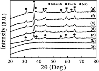 | ||
| Fig. 1 XRD patterns of the obtained samples at different temperatures. (a) The precursor, (b) at 250 °C (c) 300 °C (d) 350 °C (e) 400 °C (f) 450 °C (g) 500 °C. | ||
Figure 2 shows the microstructure of the precursor and the sample obtained at 300 °C. It can be seen from Fig. 2a that the precursor with the particle size of 1–5 μm is spherical and relatively smooth. In contrast to the precursor, the particle size of the sample calcined at 300 °C was remarkably reduced to 0.5–2 μm, and small pores were observed on the surface of the particles. As observed from the cross-sectional views of the calcined sample (Fig. 2c and d), the spherical particles were aggregated from nano-sized grains (15–30 nm) with interconnected pores between these grains. This is because the citrate and residual acetate decomposed to gas and then cause the dense precursor spheres to vacate during the calcination process. After reaching a certain temperature, the NiCo2O4 nanocrystals began to form and a large amount of the nanocrystals slowly grew and aggregated in the sphere to form microspheres with a porous structure and, finally, a single-phase NiCo2O4 spherical powder with a micro–nano porous structure was obtained.
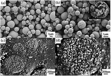 | ||
| Fig. 2 FE-SEM images of NiCo2O4 obtained at 300 °C. (a) Precursor, (b) calcined sample, (c) and (d) the cross-section at different magnifications. | ||
Fig. 3 shows the TEM images and SAED pattern of the NiCo2O4 calcined at 300 °C. It can be clearly seen from the images (Fig. 3a–c) that there are voids in the NiCo2O4 microspheres, indicating that the particles inside have lots of nanopores. These voids can store electrolytes and promote ion exchange between the electrolyte and electrode material, resulting in an improved electrochemical performance.26 The SAED pattern (Fig. 3d) shows an obvious polycrystalline diffraction aura, which indicates that NiCo2O4 is polycrystalline. By indexing to the Fd3m space group of the spinel NiCo2O4 cube, the crystal surfaces were labeled as (311) (400) and (440), respectively.
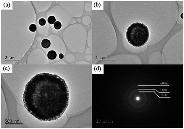 | ||
| Fig. 3 (a)–(c) TEM images of different magnifications and (d) the SAED pattern of the calcined NiCo2O4. | ||
Fig. 4 shows the specific surface area and pore diameter distributions of the NiCo2O4 powder obtained at 300 °C. Fig. 4a shows that the N2 adsorption-curve of the sample is the IV type, indicating the presence of micropores or mesopores. It can be seen from Fig. 4b that the pore structure does exist in the sample particles. The specific surface area of NiCo2O4 powder is 42.17 m2 g−1, and the pore diameter is concentrated in 5–30 nm, with an average of 4.233 nm. The nano-sized pores are conducive to increasing the specific surface area so that sites are available for increased electron conduction in NiCo2O4.
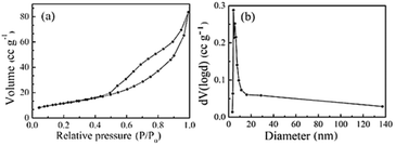 | ||
| Fig. 4 N2 adsorption and desorption isotherms of the samples obtained at 300 °C. (a) Specific surface area (BET) (b) pore-size distribution (BJH). | ||
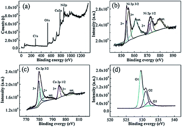
Fig. 5 shows the XPS spectra of the surface of the calcined NiCo2O4. The survey spectrum (Fig. 5a) indicates the presence of Ni, Co, and O, as well as C based on the reference and the absence of other impurities. By using the Gaussian fitting method, the Ni 2p emission spectrum (Fig. 5b) exhibits two spin–orbit bimodal emission peaks, namely Ni2+ and Ni3+ and two shake-up satellite peaks (“sat.”). The binding energies at 854.79 eV and 871.62 eV belong to Ni2+, and the binding energies at 855.36 eV and 873.32 eV belong to Ni3+.27 The Co 2p spectrum (Fig. 5c) are well fitted with two spin–orbit doublet peaks characteristic of Co2+ and Co3+ and two shake-up satellite peaks. The peaks with binding energies of 781.10 eV and 796.86 eV were derived from Co2+, and those at 779.56 eV and 794.82 eV are ascribed to Co3+.28 As shown in Fig. 5d, the O 1s spectrum shows three oxygen-donating groups. O 1(529.54 eV) is a typical metal–oxygen bond, O 2(531.8 eV) corresponds to a defect site of low oxygen-coordination in small-sized particles, and O 3(532.2 eV) may be a variety of physically and chemically adsorbed waters on and within the surface.29 These results show that the chemical composition of porous NiCo2O4 microspheres includes Co2+, Co3+, Ni2+, and Ni3+, which is in good agreement with the results in the literature for NiCo2O4.30,31
Investigation of electrochemical performances
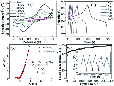
Fig. 6a shows the cyclic voltammetry (CV) curves of NiCo2O4 at a scan rate of 5–100 mV s−1. Compared with electric double-layer capacitance characterized by nearly rectangular CV,29 the shapes of the CV curves clearly confirm the pseudo-capacitive behavior. Unlike the blank nickel foam, a pair of redox peaks were observed within 0 to 0.5 V, indicating that the charge storage was achieved by NiCo2O4 loaded on the nickel foam surface by faradaic redox reactions of Co2+/Co3+ and Ni2+/Ni3+. The redox reaction is expressed as eqn (1).32,33| NiCo2O4 + OH− + H2O ↔ NiOOH + 2CoOOH + 2e− | (1) |
As the scan rate increased, the area of the CV curve increased and the position of the cathodic peak shifted from 0.22 to 0.15 V, indicating the low resistance of the electrode because of the conductive Ni substrate. Fig. 6b shows the galvanostatic charge and discharge curves of the sample in the 0–0.45 V range at different current densities. Distinctly, the existence of plateaus at around 0.25 V suggests an ideal pseudocapacitance, which is in good agreement with the CV curves (Fig. 6a). The specific capacitance was calculated according to eqn (2):
| Cs = IΔt/mΔV | (2) |
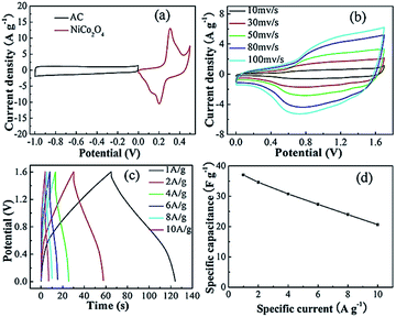
Fig. 7a shows the CV curve of the positive and negative materials at a sweep speed of 10 mV s−1. By using the specific electricity calculation formula, it was found that the mass ratio of the positive and negative electrodes was about 0.8![[thin space (1/6-em)]](https://www.rsc.org/images/entities/char_2009.gif) :
:![[thin space (1/6-em)]](https://www.rsc.org/images/entities/char_2009.gif) 1. Fig. 7b shows the CV curves for different scan rates of NiCo2O4//AC, where it can be seen that the potential window is significantly expanded to 1.7 V and the shape of the curve is different from that of the electric double-layer and pseudocapacitor. On increasing the scanning rate, the response current increased accordingly and the shape of the curve remained good, indicating good dynamic performance. Fig. 7c shows the charge–discharge curves at different current densities. The assembled supercapacitor achieved the purpose of expanding the voltage window and obtaining higher power and it was observed that each curve exhibited good symmetry at a higher current density. There is no obvious voltage drop, which indicates that the characteristics of the pseudocapacitance capacitor are still dominant after it is assembled into an asymmetric supercapacitor, which has ideal capacitive behavior, high coulombic efficiency and excellent electrical conductivity. Fig. 7d is a comparison of the specific capacities at different current densities. The specific capacitances at the current densities of 1, 2, 4, 6, 8 and 10 A g−1 were calculated by eqn (2) to be 37.06, 34.63 30.75, 27.37, 24, and 20.63 F g−1, respectively. In contrast to the capacity at 1 A g−1, the capacity retention rate at 10 A g−1 is 55.7%, indicating that the assembled capacitors exhibit better electrochemical performance. Subsequently, further cyclic life tests are needed to observe the structural stability of pseudocapacitive electrode materials.
1. Fig. 7b shows the CV curves for different scan rates of NiCo2O4//AC, where it can be seen that the potential window is significantly expanded to 1.7 V and the shape of the curve is different from that of the electric double-layer and pseudocapacitor. On increasing the scanning rate, the response current increased accordingly and the shape of the curve remained good, indicating good dynamic performance. Fig. 7c shows the charge–discharge curves at different current densities. The assembled supercapacitor achieved the purpose of expanding the voltage window and obtaining higher power and it was observed that each curve exhibited good symmetry at a higher current density. There is no obvious voltage drop, which indicates that the characteristics of the pseudocapacitance capacitor are still dominant after it is assembled into an asymmetric supercapacitor, which has ideal capacitive behavior, high coulombic efficiency and excellent electrical conductivity. Fig. 7d is a comparison of the specific capacities at different current densities. The specific capacitances at the current densities of 1, 2, 4, 6, 8 and 10 A g−1 were calculated by eqn (2) to be 37.06, 34.63 30.75, 27.37, 24, and 20.63 F g−1, respectively. In contrast to the capacity at 1 A g−1, the capacity retention rate at 10 A g−1 is 55.7%, indicating that the assembled capacitors exhibit better electrochemical performance. Subsequently, further cyclic life tests are needed to observe the structural stability of pseudocapacitive electrode materials.
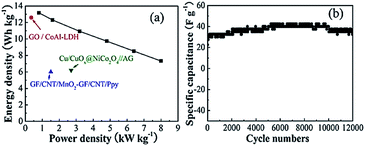
Fig. 8a shows the calculation results of the power density and energy density of the assembled supercapacitor according to formulas (3) and (4).
| E = CsΔV2/2 | (3) |
| P = E/t | (4) |
![[thin space (1/6-em)]](https://www.rsc.org/images/entities/char_2009.gif) 000 cycles at a current density of 4 A g−1, the capacitance retention was 100%, suggesting its excellent cycling stability.
000 cycles at a current density of 4 A g−1, the capacitance retention was 100%, suggesting its excellent cycling stability.
The above results indicate that the spherical porous NiCo2O4 electrode material with micro–nano structure is beneficial for exhibiting the pseudocapacitor characteristics, diffusion and transfer of charges and increase in the structural stability and cycle life during the charge–discharge process.
Conclusions
The micro–nano structured porous NiCo2O4 microspheres prepared by spray drying exhibited superior electrochemical properties. Electrochemical tests showed that their specific capacitance was 430.67 and 317.78 F g-1 at current densities of 1 and 10 A g-1, respectively. The NiCo2O4 electrode has a specific capacitance of 398.22 F g−1 after 3000 cycles at 4 A g−1 current density, and the capacity retention rate is 100%. Therefore, the micro–nano structured porous spherical NiCo2O4 powder is a promising candidate for a supercapacitor. On being assembled into an asymmetric supercapacitor, device testing showed specific capacitances of 37.06 F g−1 and 20.63 F g−1 at current densities of 1 and 10 A g−1 and an energy density of 13.18 W h kg−1 at a power density of 800 W kg−1. The spherical porous NiCo2O4 electrode material with a micro–nano structure is beneficial for exhibiting pseudocapacitor characteristics, the diffusion and transfer of charges and an increase in the structural stability and cycle life during the charge–discharge process.Conflicts of interest
There are no conflicts to declare.Acknowledgements
The work was financially supported by Natural Science Foundation of Liaoning Province of China (No. 2019-ZD-0122).References
- Y. Wang, Z. Q. Shi, Y. Huang, Y. F. Ma, C. Y. Wang, M. M Chen and Y. S. Chen, J. Mater. Chem., 2009, 113, 13103 CAS.
- L. Wang, J. Yu, X. T. Dong, S. H. Chen, P. Li, H. Q. Hou and Y. H. Song, ACS Sustainable Chem. Eng., 2016, 4, 1531 CrossRef CAS.
- R. K. Prataap, R. Arunachalam and R. P. Raj, Curr. Appl. Phys., 2018, 18, 1143 CrossRef.
- R. J. Zou, K. B. Xu, T. Wang, G. J. He, Q. Liu, X. J. Liu, Z. Y. Zhang and J. Q. Hu, J. Mater. Chem. A, 2013, 30, 8560 RSC.
- H. L. Wang, Q. M. Gao and L. Jiang, Small, 2011, 17, 2454 Search PubMed.
- G. Q. Zhang and X. W. Lou, Sci. Rep., 2013, 3, 1470 CrossRef PubMed.
- Q. F. Wang, X. F. Wang, B. Liu, G. Yu, X. J. Hou, D. Chen and G. Z. Shen, J. Mater. Chem. A, 2013, 7, 2468 RSC.
- C. Liu, W. Jiang, F. Hu, F. Wu and D. F. Xue, Inorg. Chem. Front., 2018, 5, 835 RSC.
- H. W. Wang, Z. A. Hu and Y. Q. Chang, J. Mater. Chem., 2011, 21, 10504 RSC.
- Y. Zhu, X. Pu, W. Song, Z. Wu, Z. Zhou, X. He, M. Jing, B. Tang and X. Ji, J. Alloys Compd., 2014, 617, 988 CrossRef CAS.
- Q. Wang, X. Wang, B. Liu, G. Yu, X. Hou, D. Chen and G. Shen, J. Mater. Chem. A, 2013, 1, 2468 RSC.
- M. Kuang, Y. X. Zhang, T. T. Li, K. F. Li, S. M. Zhang, G. Li and W. Zhang, J. Power Sources, 2015, 283, 270 CrossRef CAS.
- H. Adhikari, D. Neupane, C. K. Ranaweera, J. Candler, R. K. Gupta, S. Sapkota, X. Shen and S. R. Mishra, Electrochim. Acta, 2017, 225, 514 CrossRef CAS.
- H. Jiang, J. Ma and C. Z. Li, Chem. Commun., 2012, 48, 4465 RSC.
- P. Yang, D. Zhao, D. I. Margolese, B. F. Chmelka and G. D. Stucky, Nature, 1998, 396, 152 CrossRef CAS.
- T. Wang, Y. Guo, B. Zhao, S. Yu, H. P. Yang, D. Lu, X. Z. Fu, R. Sun and C. P. Wong, J. Power Sources, 2015, 286, 371 CrossRef CAS.
- L. Yu, G. Q. Zhang, C. Q. Yuan and X. W. Lou, Chem. Commun., 2013, 49, 137 RSC.
- X. Y. Liu, S. J. Shi, Q. Q. Xiong, Y. J. Zhang, H. Tang, C. D. Gu, X. L. Wang and J. P. Tu, ACS Appl. Mater. Interfaces, 2013, 17, 8790 CrossRef.
- Y. Y. Mi, P. Gao, W. Liu, W. Zhang and H. H. Zhou, J. Power Sources, 2014, 267, 459 CrossRef CAS.
- X. L. Wu, L. Y. Jiang, F. F. Cao, Y. G. Guo and L. J. Wan, Adv. Mater., 2009, 21, 2710 CrossRef CAS.
- S. Wen, G. Li, R. Ren and C. Li, Mater. Lett., 2015, 148, 130 CrossRef CAS.
- C. Li, G. Li and X. Guan, J. Energy Chem., 2018, 27, 923 CrossRef.
- C. Hu and Y. Lee, Mater. Chem., 1997, 48, 246 CAS.
- B. Cui, H. Lin, J. B. Li, X. Li, J. Yang and J. Tao, Adv. Funct. Mater., 2008, 18, 1440 CrossRef CAS.
- Y. Q. Wu, X. Y. Chen, P. T. Ji and Q. Q. Zhou, Electrochim. Acta, 2011, 56, 7517 CrossRef CAS.
- Q. Liu, J. Yang, R. Wang, H. Wang and S. Ji, RSC Adv., 2017, 7, 33635 RSC.
- M. J. Pang, S. Jiang, G. H. Long, Y. Ji, W. Han, B. Wang, X. L. Liu, Y. L. Xi, F. Z. Xu and G. D. Wei, RSC Adv., 2016, 6, 67839 RSC.
- P. Hao, J. Tian, Y. Sang, C. C. Tuan, G. W. Cui, X. F. Shi, C. P. Wong, B. Tang and H. Liu, Nano, 2016, 8, 16292 CAS.
- X. F. Lu, D. J. Wu, R. Z. Li, Q. Li, S. H. Ye, Y. X. Tong and G. R. Li, J. Mater. Chem. A, 2014, 2, 4706 RSC.
- L. F. Shen, Q. Che, H. S. Li and X. G. Zhang, Adv. Funct. Mater., 2014, 24, 2630 CrossRef CAS.
- S. Li, S. Xiong, Y. Liu, Z. Ju and Y. Qian, ACS Appl. Mater. Interfaces, 2013, 5, 981 CrossRef PubMed.
- S. Gao, F. Liao, S. Ma, L. Zhu and M. Shao, J. Mater. Chem. A, 2015, 3, 16520 RSC.
- W. Liu, C. Lu, K. Liang and B. K. Tay, J. Mater. Chem. A, 2014, 2, 5100 RSC.
- A. C. Nwanya, S. U. Offiah, I. C. Amaechi, S. Agbo, S. C. Ezugwu, B. T. Sone, R. U. Osuji, M. Maaza and F. I. Ezema, Electrochim. Acta, 2015, 171, 128 CrossRef CAS.
- X. Xie, Z. Chang, Y. Tao, W. Lv and Q. H. Yang, Chem. Commun., 2013, 49, 11092 RSC.
- D. Cai, B. Liu, D. Wang, L. Wang, Y. Liu, H. Li, Y. Wang, Q. Li and T. Wang, J. Mater. Chem. A, 2014, 2, 4954 RSC.
- N. Padmanathan and S. Selladurai, RSC Adv., 2014, 4, 8341 RSC.
- R. Zhang, H. An, Z. Li, M. F. Shao, J. B. Han and M. Wei, Chem. Eng. J., 2016, 289, 85 CrossRef CAS.
- J. L. Liu, L. L. Zhang, H. B. Wu, J. Y. Lin, Z. X. Shen and X. W. Lou, Energy Environ. Sci., 2014, 7, 3709 RSC.
| This journal is © The Royal Society of Chemistry 2020 |

