 Open Access Article
Creative Commons Attribution 3.0 Unported Licence
Photoelectrochemical photocurrent switching effect on a pristine anodized Ti/TiO2 system as a platform for chemical logic devices†
Nikolay V. Ryzhkov ,
Veronika Yu. Yurova,
Sviatlana A. Ulasevich and
Ekaterina V. Skorb
 *
*
ITMO University, 9, Lomonosova street, Saint Petersburg, 191002, Russia. E-mail: skorb@itmo.ru
First published on 26th March 2020
Abstract
We report here the effect of the photoelectrochemical photocurrent switching (PEPS) observed on highly-ordered pristine anodized Ti/TiO2 for the first time. At negative potential bias, blue irradiation gives cathodic photocurrent, whereas anodic photocurrent was observed for ultraviolet irradiation. We believe this phenomenon is due to the electron pathway provided by Ti3+ defect states.
Titanium dioxide, being one of the most studied materials, still draws much attention from researchers.1,2 It is considered to be a very promising material due to its high chemical stability, nontoxicity, and its unique properties. Due to stable and robust photoactivity, titania is widely used in the design of solar cells3 and photocatalytic applications.4 In addition to the fact that titanium dioxide occurs in several crystalline modifications, it can also be obtained in various forms, such as, for example, nanotubes,5 nanofibers,6 and nanosheets.7 The photocatalytic performance of TiO2 is highly dependent on crystallinity,8 phase content, form, and preparation method.9 It was reported that highly ordered arrays of TiO2 nanotubes are characterized by short charge transport distance and little carrier transport loss.5 Therefore, electrochemically fabricated TiO2 nanotube arrays are preferable compared to random non-oriented titania.10 Great varieties of photoelectrochemical behaviour can be achieved by doping11 and surface modification.12,13
An interesting feature has recently been demonstrated for highly ordered arrays of TiO2 nanotubes obtained by double stepwise electrochemical anodization of a titanium foil (Ti/TiO2). Together with our colleagues observed that localized illumination of Ti/TiO2 surface in water solution triggers proton flux from irradiated area.14 The photocatalytic activity of TiO2 is based on photogenerated electron–hole pairs. Under the electric field of Ti/TiO2 Schottky junction and due to upward surface band bending, efficient spatial charge separation occurs, and photoexcited holes (h+) reach TiO2 – solution interface. The h+, which is a strong oxidizing agent, can react with water, and a pronounced pH gradient arises due to water photolysis. Thus, titanium dioxide can be used to trigger local ion fluxes, and proton release is associated with anodic photocurrent. The use of the light-pH coupling effect to control pH-sensitive soft matter was previously demonstrated.15,16 Complementary species, H+ and OH−, annihilating when occurring simultaneously, extend chemical arithmetic with subtraction operation opening way to pure chemical calculations.17 Ion fluxes consideration as information transducers in solution were proposed18 and performing simple logic operations was demonstrated.19 This phenomenon opens perspectives to biomimetic information processing and developing effective human–machine interfaces.20
Photoelectrodes using light and potential as inputs and yielding photocurrents are being considered as the basis for logic devices. In this way, optical computing compatible with existing silicon-based devices may be performed.
Logic operations are described by Boolean algebra operating with truth values denoted 0 (false) and 1 (true). Elementary logical operations are modelled by logic gates producing single binary output from multiple binary inputs and physically implemented by some switch. As for photoelectrode based information processing, the photoelectrochemical photocurrent switching (PEPS) effect is utilized. This effect is that under appropriate external polarization or/and illumination by light with appropriate photon energy, switching between anodic and cathodic photocurrent may be observed for n-type semiconductors and the opposite for p-type.21,22
Without further modification, this effect was observed for a very limited number of materials, such as bismuth orthovanadate, lead molybdate, V–VI–VII semiconductors, and some others. To show this effect, the majority of semiconductors require electronic structure perturbation creating new electron pathways. A convenient solution is specific modifier adsorption onto the semiconductors' surface, providing a sufficient level of electronic coupling. Photoelectrodes made of nanocrystalline TiO2 modified by cyanoferrate,13,23 and ruthenium24 complexes, thiamine, folic acid,25 and carminic acid26 demonstrated PEPS behavior.
Surprisingly, we observed the PEPS effect on non-modified Ti/TiO2 obtained by anodation of Ti plates.
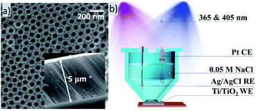
Highly ordered arrays of anatase Ti/TiO2 were obtained. Crystallinity was proved by XRD (Fig. S1a†). Fig. 1a shows a SEM image of TiO2 nanotube arrays obtained as described above. According to SEM image, an average pore diameter is ca. 60 nm. As reported, highly ordered TiO2 nanotubes possess a short charge transport distance and little carrier transport loss. Therefore, highly ordered TiO2 nanotube arrays fabricated by electrochemical anodization of titanium may exhibit some enhanced capacity of electron transfer than non-oriented ones of random mixture.10
According to Mott–Schottky analysis, at potential bias more positive than −0,697 V vs. Ag/AgCl reference electrode upwards band bending occurs (Fig. S2†). Heat treatment in a nonoxidizing atmosphere leads to Ti3+ formation. Appearance of Ti3+ self-doping was proved by EDX analysis (Fig. S1b†). It was previously reported that Ti3+ introduces gap states which act as recombination centers and pathways for electron transfer.27–29 Ti3+ species in reduced TiO2 introduce a gap state between valence and conduction bands.27,28
We studied dependence of photocurrent on applied potential. Ultraviolet irradiation (365 nm) gave positive photocurrent for all potentials studied in range from −0.6 V to 0.6 V vs. Ag/AgCl reference electrode (Fig. S3†). The photocurrent increases as the potential becomes more positive, but eventually saturates. The dependence of the current on the potential under blue irradiation (405 nm) had a different character. Sigmoid function with inflection point at 0–0.2 V was observed for blue light.
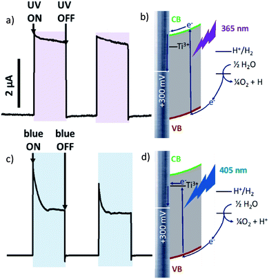
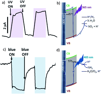
It should be noticed that photocurrent plotted against time on Fig. 2–4 as well as against potential on Fig. S3† is ΔI = Iunder illumination − Iin darkness. Steady state current values were used for calculations.
At +300 mV vs. Ag/AgCl irradiation by both blue and ultraviolet light give anodic photocurrent (Fig. 2a and c). The UV-irradiation (λ = 365 nm, 5 mW cm−2) excites electron directly to the conduction band (CB) of TiO2, which is further transferred to conducting titanium support (Fig. 2b). When Ti/TiO2 electrode in thermodynamic equilibrium with electrolyte, an upward surface band bending occurs at the semiconductor–liquid junction. This phenomenon obstructs electron injection from the conduction band into the electrolyte and forces electron drift to conducting substrate. The fast and steady photocurrent production/extinction upon light on/off indicates efficient charge separation and low recombination.
Blue light (λ = 405 nm, 70 mW cm−2) is characterized by lower energy than UV-irradiation, which is not sufficient to excite the electron to CB. But electron excited by blue light can be trapped by Ti3+ located close to the conduction band and transferred to conduction support from these levels (Fig. 2c). An initial current spike following by an exponential decrease suggesting a fast recombination process. It should be also noticed than when irradiation is switched off photocurrent ‘overshoots’ as the remaining surface holes continue to recombine with electrons.
At more negative potential (−300 mV vs. Ag/AgCl, for example) applied to non-modified anodized Ti/TiO2 photoelectrode, we observed anodic photocurrent during irradiation by UV light (Fig. 3a) whereas blue irradiation gave anodic photocurrent (Fig. 3c). Excitation within bandgap by UV-irradiation leads to cathodic photocurrent (Fig. 3b). In the case of irradiation by blue light, electron trapping by Ti3+ occurs in the same manner as at +300 mV polarization. But at negative polarization, the energy landscape is such that electron transport to electron donor in solution is preferable (Fig. 3d). As a result, cathodic current occurs.
Thereby, photoelectrode activity of non-modified anodized Ti/TiO2 can be switched from anodic to cathodic and vice versa by applying various potentials and various photon energies. This is the effect of photoelectrochemical photocurrent switching.
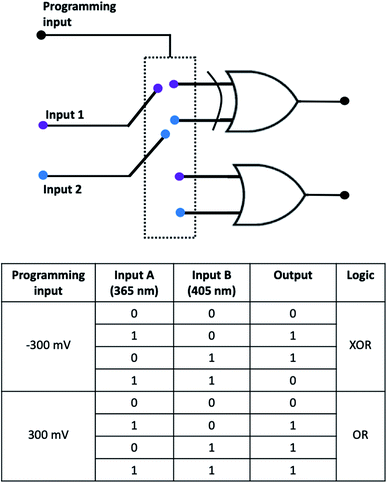
Thereby, when Ti/TiO2 is irradiated simultaneously by blue and UV light being negatively polarized, competition between cathodic and anodic photocurrents occurs. Returning to Boolean logic, the PEPS effect allows us to perform annihilation of two input signals and implement optoelectronic XOR logic gate. XOR logic operation outputs true (1) only when input values are different and yield zero otherwise.
It is necessary to assign logic values to input and output signals to analyse the system based on Ti/TiO2 PEPS effect in terms of Boolean logic. Logical 0 and 1 are assigned to off and on states of the LEDs, respectively. Different wavelengths (365 and 405 nm) correspond to two different inputs of the logic gate. In the same way, we can assign logic 0 to the state when photocurrent is not generated and logic 1 to any nonzero photocurrent intensity irrespectively on its polarization (cathodic or anodic).
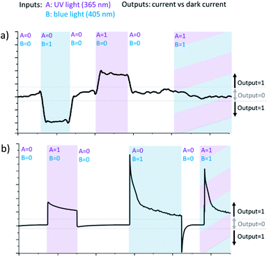
Fig. 4 demonstrates how different types of Boolean logic are realized by irradiation of Ti/TiO2. Light sources are denoted here as inputs, UV light – A and blue light – B. If the corresponding light source is switched ON and illuminates photoelectrode Ti/TiO2, this input is ‘1’, otherwise, it's ‘0’. The photocurrent is read as output. It's considered to be ‘1’ if significantly differs from dark value and ‘0’ otherwise.
At −300 mV vs. Ag/AgCl, pulsed irradiation with UV diode (365 nm, 5 mW cm−2) results in anodic photocurrent, which is consistent with electron excitation to CB and transfer to conducting support. Irradiation with blue LED (405 nm) gives cathodic photocurrent due to electron capture by Ti3+ states following by transferring to electron acceptor in solution. Simultaneous irradiation with two LEDs with adjusted intensity yields zero net current as anodic and cathodic photocurrents compensate effectively (Fig. 4a).
At positive potentials, pulsed irradiation with UV diode gives anodic photocurrent pulses, as well as the blue one. It is interesting to note that when two sources of light are simultaneously irradiated, the photocurrents created by each of them individually do not summarize. At +300 mV, photocurrent output under the influence of two light inputs (365 nm and 405 nm) follows OR logic giving positive output if at least one of inputs is positive (Fig. 4b).
Fig. 5 demonstrates the reconfigurable logic system which characteristics can be changed via an appropriate polarization of the photoelectrode regarded as programming input. Two irradiation sources are considered as inputs. OR/XOR logic is realized depending on programming input.
In summary, PEPS effect on modified nanocrystalline TiO2 was previously discussed a lot.13,23–26 In this work we report the same phenomenon for pristine anodized Ti/TiO2 system. Due to substructure of Ti/TiO2 system, it shows characteristic response to various range of illumination, including visible range and polarization. The Ti/TiO2 system is a simple and robust model of chemical logic gates. Suggested mimicking of logic functions in aqueous solutions allows further integration of element into communication with living objects16 vs. intrinsically associated photooxidation and degradation, but rather activation for needed function.30
Experiment
Highly ordered arrays of photoactive crystalline TiO2 nanotubes can be obtained by double two-stage anodization of titanium substrates in ethylene glycol electrolyte containing fluoride ions. Double anodization involves forming a first anodization layer and an adjacent second anodization layer on an angled surface, the interface between the two anodization layers being regular and uniform. Anodization was performed via two stages where at the first stage the anode was linearly polarized from 0 to 40 V, and then at the second stage, the electrode was polarized at a constant voltage of 40 V. The as prepared Ti/TiO2 were treated ultrasonically in ethanol for 0.5–1 min to remove the debris and annealed at 450 °C for 3 hours.For Mott–Schottky analysis potential was scanned from −1.0 to +0.4 with increment 0.04 V and 3 minutes delay for equilibration of each potential. Potential were oscillating with amplitude 0.005 V and frequency 1000 Hz.
Photocurrent measurements were performed in 3-electrode cell with Ti/TiO2 nanotubes plate as working electrode, Pt counter electrode and Ag/AgCl reference electrode. During each measurement desired potential bias was applied and after establishing a constant stable dark current working electrode was illuminated by UV LED (365 nm) or blue LED (405 nm) or both light sources simultaneously.
For Boolean logic implementation light intensity was adjusted the light intensity was adjusted in such a way that under −0.3 V polarization photoresponses on UV and blue light annihilate.
Conflicts of interest
There are no conflicts to declare.Acknowledgements
The reported study was funded by RSF grant no. 17-79-20186. N. V. R. acknowledges RFBR project number 19-33-90163. ITMO Fellowship Professorship Program is acknowledged for Infrastructural Support.Notes and references
- E. Zghab, M. Hamandi, F. Dappozze, H. Kochkar, M. S. Zina, C. Guillard and G. Berhault, Mater. Sci. Semicond. Process., 2020, 107, 104847 CrossRef.
- R. Nebel, K. M. Macounová, H. Tarábková, L. Kavan and P. Krtil, J. Phys. Chem. C, 2019, 123, 10857 CrossRef CAS.
- J. R. Jennings, A. Ghicov, L. M. Peter, P. Schmuki and A. B. Walker, J. Am. Chem. Soc., 2008, 130, 13364 CrossRef CAS.
- S. P. Albu, A. Ghicov, J. M. Macak, R. Hahn and P. Schmuki, Nano Lett., 2007, 7, 1286 CrossRef CAS PubMed.
- K. Lee, A. Mazare and P. Schmuki, Chem. Rev., 2014, 114, 9385 CrossRef CAS PubMed.
- A. Kumar, R. Jose, K. Fujihara, J. Wang and S. Ramakrishna, Chem. Mater., 2007, 19, 6536 CrossRef CAS.
- W. Q. Fang, J. Z. Zhou, J. Liu, Z. G. Chen, C. Yang, C. H. Sun, G. R. Qian, J. Zou, S. Z. Qiao and H. G. Yang, Chem.–Eur. J., 2011, 17, 1423 CrossRef CAS.
- J. Zhang, P. Zhou, J. Liu and J. Yu, Phys. Chem. Chem. Phys., 2014, 16, 20382 RSC.
- S. K. Choi, S. Kim, S. K. Lim and H. Park, J. Phys. Chem. C, 2010, 114, 16475 CrossRef CAS.
- P. Roy, S. Berger and P. Schmuki, Angew. Chem., Int. Ed., 2011, 50, 2904 CrossRef CAS PubMed.
- A. Ghicov, J. M. Macak, H. Tsuchiya, J. Kunze, V. Haeublein, L. Frey and P. Schmuki, Nano Lett., 2006, 6, 1080 CrossRef CAS.
- N. Brezhneva, A. Nikitina, N. Ryzhkov, A. Klestova, A. V. Vinogradov and E. V. Skorb, J. Sol-Gel Sci. Technol., 2019, 89, 92 CrossRef CAS.
- W. Macyk, G. Stochel and K. Szaciłowski, Chem.–Eur. J., 2007, 13, 5676 CrossRef CAS PubMed.
- H. M. Maltanava, S. K. Poznyak, D. V. Andreeva, M. C. Quevedo, A. C. Bastos, J. Tedim, M. G. S. Ferreira and E. V. Skorb, ACS Appl. Mater. Interfaces, 2017, 9, 4282 CrossRef PubMed.
- S. A. Ulasevich, G. Brezesinski, H. Möhwald, P. Fratzl, F. H. Schacher, S. K. Poznyak, D. V. Andreeva and E. V. Skorb, Angew. Chem., Int. Ed., 2016, 55, 13001 CrossRef CAS PubMed.
- S. A. Ulasevich, N. Brezhneva, Y. Zhukova, H. Möhwald, P. Fratzl, F. H. Schacher, D. V. Sviridov, D. V. Andreeva and E. V. Skorb, Macromol. Biosci., 2016, 16, 1422 CrossRef CAS PubMed.
- P. Banda, C. Teuscher and D. Stefanovic, J. R. Soc., Interface, 2014, 11, 20131100 CrossRef PubMed.
- N. V. Ryzhkov, N. A. Mamchik and E. V. Skorb, J. R. Soc., Interface, 2019, 16, 20180626 CrossRef PubMed.
- N. V. Ryzhkov, P. Nesterov, N. A. Mamchik, S. O. Yurchenko and E. V. Skorb, Front. Chem., 2019, 7, 419 CrossRef CAS PubMed.
- N. V. Ryzhkov, D. V. Andreeva and E. V. Skorb, Langmuir, 2019, 35, 8543 CrossRef CAS PubMed.
- K. Pilarczyk, P. Kwolek, A. Podborska, S. Gawęda, M. Oszajca and K. Szaciłowski in Advances in Unconventional Computing, ed. A. Adamatzky, Springer, Cham, 2017, pp.429–467 Search PubMed.
- M. ce Long, R. Beranek, W. min Cai and H. Kisch, Electrochim. Acta, 2008, 53, 4621 CrossRef.
- K. Szaciłowski, W. Macyk, M. Hebda and G. Stochel, ChemPhysChem, 2006, 7, 2384 CrossRef PubMed.
- L. F. O. Furtado, A. D. P. Alexiou, L. Gonçalves, H. E. Toma and K. Araki, Angew. Chem., Int. Ed., 2006, 45, 3143 CrossRef CAS PubMed.
- S. Gawȩda, G. Stochel and K. Szaciłowski, Chem.–Asian J., 2007, 2, 580 CrossRef PubMed.
- S. Gawȩda, G. Stochel and K. Szaciłowski, J. Phys. Chem. C, 2008, 112, 19131 CrossRef.
- M. Nolan, S. D. Elliott, J. S. Mulley, R. A. Bennett, M. Basham and P. Mulheran, Phys. Rev. B: Condens. Matter Mater. Phys., 2006, 77, 235424 CrossRef.
- C. Di Valentin, G. Pacchioni and A. Selloni, J. Phys. Chem. C, 2009, 113, 20543 CrossRef CAS.
- J. Weidmann, T. Dittrich, E. Konstantinova, I. Lauermann, I. Uhlendorf and F. Koch, Sol. Energy Mater. Sol. Cells, 1999, 56, 153 CrossRef CAS.
- E. V. Skorb, D. V. Andreeva, A. P. Raiski, N. A. Belyasova, H. Möhwald and D. V. Sviridov, Photochem. Photobiol. Sci., 2011, 10, 1974 RSC.
Footnote |
| † Electronic supplementary information (ESI) available: Additional details concerning experimental conditions. See DOI: 10.1039/d0ra00205d |
| This journal is © The Royal Society of Chemistry 2020 |

