
 Open Access Article
 This Open Access Article is licensed under a
 Creative Commons Attribution 3.0 Unported Licence
Europium oxide nanorod-reduced graphene oxide nanocomposites towards supercapacitors
Parisa Aryanrada,
Hamid Reza Naderib,
Elmira Kohanc,
Mohammad Reza Ganjali ad,
Masoud Baghernejade and
Amin Shiralizadeh Dezfuli*f
ad,
Masoud Baghernejade and
Amin Shiralizadeh Dezfuli*f
aCenter of Excellence in Electrochemistry, Faculty of Chemistry, University of Tehran, Tehran, Iran
bNovin Ebtekar Company, Exclusive Agent of Metrohm-Autolab, Dropsens Companies, Tehran, Iran
cRonash Technology Pars Company, Tehran, Iran
dBiosensor Research Center, Endocrinology & Metabolism Molecular-Cellular Sciences Institute, Tehran University of Medical Sciences, Tehran, Iran
eHelmholtz-Institute Münster, Forschungszentrum Jülich GmbH, Corrensstraße 46, 48149 Münster, North Rhine-Westphalia, Germany
fRadiation Biology Research Center, Iran University of Medical Sciences (IUMS), Tehran, Iran. E-mail: amindezfuli@outlook.com
First published on 6th May 2020
Abstract
Fast charge/discharge cycles are necessary for supercapacitors applied in vehicles including, buses, cars and elevators. Nanocomposites of graphene oxide with lanthanide oxides show better supercapacitive performance in comparison to any of them alone. Herein, Eu2O3 nanorods (EuNRs) were prepared through the hydrothermal method and anchored onto the surface of reduced graphene oxide (RGO) by utilizing a sonochemical procedure (in an ultrasonic bath) through a self-assembly methodology. The morphologies of EuNRs and EuNR-RGO were characterized by scanning electron microscopy (SEM), X-ray diffraction (XRD) and IR spectroscopy. Then, we used EuNRs and EuNR-RGO as electrode materials to investigate their supercapacitive behavior using cyclic voltammetry, galvanostatic charge–discharge, and electrochemical impedance spectroscopy techniques. In a 3.0 M KCl electrolyte and with a scan rate of 2 mV s−1, EuNR-RGO exhibited a specific capacity of 403 F g−1. Galvanostatic charge–discharge experiments demonstrated a specific capacity of 345.9 F g−1 at a current density of 2 A g−1. The synergy between RGO's flexibility and EuNR's high charge mobility caused these noticeable properties.
1. Introduction
Nowadays, supercapacitors due to their high energy density, have been investigated as storage devices and due to this property, they have been given particular priority over conventional dielectric capacitors. Because of some features such as good cycling stability, fast charge/discharge rate, and high power density, supercapacitors are superior to batteries.1 Electric double-layer capacitors (EDLCs) and pseudo-capacitors are major types of supercapacitors.2–5 In pseudo-capacitors, the electrodes contain oxides of noble and transition metals or conducting polymers, whereas the main materials in EDLCs are carbonaceous materials such as carbon nanotubes (CNTs) or graphene.5,6 The latter group of electrode materials owns unique features such as thermal and chemical stabilities, very high conductivity, and considerable surface area.7Distinctive reduced graphene oxide (RGO), obtained through the reduction of graphene oxide (GO), owing to its low-cost approach has gained considerable attention among other nanomaterials.8 Moreover, reduced graphene oxide can be decorated with various nanomaterials and the properties of the resulting hybrid nanomaterials can be fine-tuned by modifying the loading degree as well as the type of the nanomaterial loaded on the RGO sheets.8–13 A group of materials used for the decoration of RGO comprises metal oxides like MnO2, Mn3O4, RuO2, CeO2, Yb2O3 and SnO2, which avoids decrease in the surface area of RGO via the interplanar spacing of metal oxides.14,15 Open places are formed among the sheets by anchoring metal oxides on RGO; thus, the internal resistance of the material is greatly diminished and subsequently, the penetration of electrolytes in the electrodes becomes smooth.16 Due to the above-mentioned modifications, the capacitance and energy density of carbonaceous supercapacitors have increased.2,15,17,18
On the other hand, numerous studies have been carried out on lanthanide oxides or in other words rare earth oxides (REOs), because of their extensive utilizations in fuel cells, heterogeneous catalysis, ion glass industries and electronics.19–24 Some REOs are considered potential candidates toward pseudo-capacitors due to their redox properties.19,25
Strategic rare earth compounds due to their electronic, optical and electrochemical characteristics arising from the electron transitions within the 4f shells, different conformation states and empty sites in the crystallization mode have been utilized in different fields such as high-performance luminescent devices, biochemical applications, catalysts and supercapacitors.26 Recently, the synthesis of one-dimensional Eu2O3 nanostructures has gained considerable attention since they possess higher packing density and a larger percentage of active sites in comparison with bulk materials.27 For instance, Pol et al.28 prepared Eu2O3 nanorods by the thermal transformation (700 °C) of ultra-sonication-induced Eu(OH)3 nanorods. In another study, Du et al.29 produced Eu2O3 nanorods through a chemical reaction at 90 °C by means of cyclohexylamine as the alkaline source. Wang et al.30 prepared Eu2O3 nanotubes, nanowires and nanorods by a hydrothermal approach. Short Eu2O3 nanorods were synthesized by Zhang et al.31 through a sol–gel method by using an aqueous solution of europium nitrate in the presence of ammonia and urea in a micro reactor made of polystyrene/polyelectrolyte. Qian et al.32 reported simple chemical precipitation for the synthesis of light rare earth hydroxide nanorods. However, a long aging time (30 days) was unavoidably needed.
In this work, we have introduced a facile two-step procedure for preparing Eu2O3 nanorods anchored on RGO (EuNR-RGO). The first step is the hydrothermal synthesis of the Eu2O3 nanorods (EuNRs) and the second step is a sonochemical self-assembly approach. By means of this process, the size of Eu2O3 decreased to the nanometer scale, due to which the surface area and redox activity were greatly enhanced. This enhancement caused special supercapacitive behavior.
2. Experimental
2.1. Materials
All the following reagents were utilized as purchased without further purification. Sulphuric acid (H2SO4), hydrochloric acid (HCl) and phosphoric acid (H3PO4) were bought from Mojallali Chemical Co. Graphite (cat #332461), europium(III) nitrate pentahydrate (Eu(NO3)3·5H2O), ammonium hydroxide (NH4OH), hydrazine hydrate (N2H4) and poly(tetra fluoro ethylene) (PTFE) were acquired from Sigma-Aldrich Co. Acetylene black (>99.9%, S. A. 80 m2 g−1) was procured from Alfa Aesar Co. The remaining materials were obtained from Merck Chemical Co.2.2. Preparing EuNRs and EuNR-RGO
For the preparation of Eu2O3 nanorods, 10 mL of 0.1 M Eu3+ was combined with 15 mL deionized water (DW) into a 120 mL Teflon jar. Ammonia (28%) was added gradually until a white precipitate was formed. Then, the Teflon jar was sealed in a stainless-steel autoclave and heated in an oven for 12 h at 120 °C. The final product was washed repeatedly with DW and ethanol (96%), dried at 90 °C, and then calcined at 550 °C to obtain EuNRs.33The hybrid EuNR-RGO was prepared via a sonochemical procedure (in an ultrasonic bath) through self-assembly, as reported in a previous work.14 Briefly, our procedure commonly included the synthesis of EuNRs and then placing the EuNRs on GO sheets, eventually reducing the loaded GO to RGO.
Six mg of the prepared EuNR powder was placed in an ultrasonic bath for 44 min to completely disperse it in 10 mL deionized water to obtain a suspension, which was continuously added to a 20 mL suspension of GO (3 mg GO in 10 mL DI water). The resulting mixture was placed under ultrasound vibration for 22 min. This was intended to anchor the nanorods onto the GO sheets. Finally, GO was reduced to RGO by adding a reducing agent (N2H4) in a boiling water bath. As a result, a black precipitate was formed and dried at 60 °C for 24 hours. Throughout the text, the material formed under these conditions shall be referred to as EuNR-RGO. Both pure EuNRs and RGO were prepared via the same method (i.e., GO was prepared from graphite flake powder using the Tour's method34).
2.3. Characterizations
The crystallographic characterization was performed via X-ray diffraction (XRD) utilizing a Philips PW-1730 X-ray diffractometer equipped with Cu Kα radiation (λ = 1.5405 Å). The morphology of the materials was studied by field-emission scanning electron microscopy (FE-SEM) by means of MIRA3 TESCAN with a gold coating. Fourier transform infrared (FTIR) spectroscopy was performed using a BRUKER EQUINOX 55 spectrophotometer.2.4. Electrochemical studies
In this research work, an electrochemical workstation (PGSTAT30, Auto lab, Netherlands) was applied and three-electrode electrochemical studies were carried out in a 3 M KOH aqueous solution. The working electrodes were fabricated for the electrochemical measurements by a mixture of the synthesized samples (i.e., pure RGO and EuNRs and also EuNR-RGO nanocomposites) with carbon black, graphite and polytetrafluoroethylene at a 65![[thin space (1/6-em)]](https://www.rsc.org/images/entities/char_2009.gif) :10:20:5 mass ratio and then dispersed in ethanol. In order to distribute the suspension over a current collector, a piece of rustproof steel, about 1 mg of the electro-active material and a 1 cm2 current collector were utilized for this purpose. Finally, the electrodes were dried in a vacuum oven at 80 °C for 4 h (Fig. 1). The electrodes constructed under these conditions have been referred to as EuNR-RGO throughout the text. Ag/AgCl and platinum electrodes were applied as the reference and counter electrodes, respectively. A three-electrode cell system was used and by electrochemical impedance spectroscopy (EIS), cyclic voltammetry (CV) and continuous cyclic voltammetry (CCV), the electrochemical performance was examined. To obtain CCV measurements, a home-made set was utilized, as described above.14,35
:10:20:5 mass ratio and then dispersed in ethanol. In order to distribute the suspension over a current collector, a piece of rustproof steel, about 1 mg of the electro-active material and a 1 cm2 current collector were utilized for this purpose. Finally, the electrodes were dried in a vacuum oven at 80 °C for 4 h (Fig. 1). The electrodes constructed under these conditions have been referred to as EuNR-RGO throughout the text. Ag/AgCl and platinum electrodes were applied as the reference and counter electrodes, respectively. A three-electrode cell system was used and by electrochemical impedance spectroscopy (EIS), cyclic voltammetry (CV) and continuous cyclic voltammetry (CCV), the electrochemical performance was examined. To obtain CCV measurements, a home-made set was utilized, as described above.14,35
 | ||
| Fig. 1 Schematic of a three-electrode system and an electrode sample made of steel grid. | ||
3. Results and discussion
3.1. Nanocomposite preparation
The preparation processes of hybrid materials made of graphene are classified into two major approaches: in situ and self-assembly processes. The in situ process involves the nucleation and growth of nanostructures in the presence of graphene derivatives (such as GO) in the reaction medium, but the other approach comprises mixing and self-assembly between previously formed nanostructures and graphene derivatives.The latter one was actually used in this work (Scheme 1). EuNRs were prepared through the hydrothermal method and redistributed on GO by the sonochemical method. The FE-SEM image (Fig. 3b) implies that the nanorods comprise primary nanoparticles through an oriented attachment growth mechanism.36 Sonochemical phenomena (i.e., high pressure and high-speed liquid jets caused by exploding bubbles) together with bonding between the europium oxide moieties and functional groups on GO caused the detachment of the EuNR moieties from rods to nanoparticles (Fig. 3) during the self-assembly process.37
 | ||
| Scheme 1 Schematic of the EuNR-RGO nanocomposite preparation process. | ||
3.2. Nanocomposite characterization
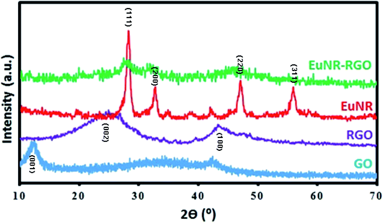 | ||
| Fig. 2 X-ray diffraction patterns of GO, RGO, EuNRs, and EuNR-RGO nanocomposites. | ||
 | ||
| Fig. 3 FE-SEM images of (a) GO, (b) EuNRs and (c and d) EuNR-RGO. | ||
![[double bond, length as m-dash]](https://www.rsc.org/images/entities/char_e001.gif) O stretching vibration at 1735 cm−1), hydroxyl groups (the peak at 1054 cm−1), epoxy groups (the C–O asymmetric vibration at 1225 cm−1) and hydrogen bonding (the broad band of O–H stretching at around 3400 cm−1).41 Meanwhile, the peak at 1625 cm−1 attributed to aromatic CC42 shifted dramatically to 1585 cm−1 after reduction in the spectra of both RGO and EuNR-RGO. It has been demonstrated that anchoring metal oxide nanostructures to the oxygen-containing functional groups such as epoxy, hydroxyl, carbonyl and carboxyl groups on the surface of GO has an important role in stacking them onto the sheets of graphene.43 Some of these functional groups (carboxyl and hydroxyl groups through the C–OH bonds) interact with metal oxides and the remaining functional groups are reduced, which causes a dramatic difference in the FT-IR spectra. Such an example is the peak at 980 cm−1 in the spectrum of EuNRs, which is assigned to the metal–oxygen bond;44 it shifted and reduced in intensity for the EuNR-RGO nanocomposite after anchoring nanoparticles to the surface functional groups of GO. Due to the reduction of GO by hydrazine at a high temperature, the characteristic absorption band of GO at 1735 cm−1 vanished, implying the successful reduction of GO in RGO and EuNR-RGO nanocomposite.42 Meanwhile, the peaks at 1088 cm−1 and 1124 cm−1 observed in the spectrum of RGO (and weakly in EuNR-RGO) are attributed to the C–N stretching vibration.45 The peak at 1384 cm−1 in the spectra of EuNR and EuNR-RGO is assigned to the adsorbed nitrosyl (N–O)−.22 The peak at 1545 cm−1 in the spectrum of EuNRs is related to the asymmetric vibration of the Eu–O bond. In addition, the peak at 1627 cm−1 in the spectra of EuNR and EuNR-RGO can be due to the bending vibration of water molecules.46
O stretching vibration at 1735 cm−1), hydroxyl groups (the peak at 1054 cm−1), epoxy groups (the C–O asymmetric vibration at 1225 cm−1) and hydrogen bonding (the broad band of O–H stretching at around 3400 cm−1).41 Meanwhile, the peak at 1625 cm−1 attributed to aromatic CC42 shifted dramatically to 1585 cm−1 after reduction in the spectra of both RGO and EuNR-RGO. It has been demonstrated that anchoring metal oxide nanostructures to the oxygen-containing functional groups such as epoxy, hydroxyl, carbonyl and carboxyl groups on the surface of GO has an important role in stacking them onto the sheets of graphene.43 Some of these functional groups (carboxyl and hydroxyl groups through the C–OH bonds) interact with metal oxides and the remaining functional groups are reduced, which causes a dramatic difference in the FT-IR spectra. Such an example is the peak at 980 cm−1 in the spectrum of EuNRs, which is assigned to the metal–oxygen bond;44 it shifted and reduced in intensity for the EuNR-RGO nanocomposite after anchoring nanoparticles to the surface functional groups of GO. Due to the reduction of GO by hydrazine at a high temperature, the characteristic absorption band of GO at 1735 cm−1 vanished, implying the successful reduction of GO in RGO and EuNR-RGO nanocomposite.42 Meanwhile, the peaks at 1088 cm−1 and 1124 cm−1 observed in the spectrum of RGO (and weakly in EuNR-RGO) are attributed to the C–N stretching vibration.45 The peak at 1384 cm−1 in the spectra of EuNR and EuNR-RGO is assigned to the adsorbed nitrosyl (N–O)−.22 The peak at 1545 cm−1 in the spectrum of EuNRs is related to the asymmetric vibration of the Eu–O bond. In addition, the peak at 1627 cm−1 in the spectra of EuNR and EuNR-RGO can be due to the bending vibration of water molecules.46
 | ||
| Fig. 4 FT-IR spectra of EuNRs, EuNR-RGO nanocomposite, GO and RGO. | ||
3.3. Electrochemical studies
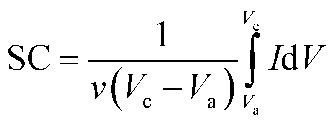
Here, ν (mV s−1) is the potential scan rate and the potential range determined with Vc and Va; the mass of the electroactive material was utilized for marking the response current (mA g−1).
 | ||
| Fig. 5 (a) Cyclic voltammograms of EuNR, RGO and EuNR-RGO electrodes in 3.0 M KCl at 50 mV s−1; (b) cyclic voltammograms of EuNR electrode in 3.0 M KCl at different scan rates from 5 to 100 mV s−1; (c) cyclic voltammograms of EuNR-RGO electrode in 3.0 M KCl at different scan rates from 5 to 100; and (d) capacitance versus sweep rate for EuNR and EuNR-RGO. | ||
Fig. 5a illustrates the cyclic voltammograms of RGO, pure EuNR and EuNR-RGO electrodes in 3.0 M KCl solutions at a scan rate of 50 mV s−1. The rectangular shapes of these curves confirm the high reversibility of the samples in this range and ideal pseudo-capacitive behavior.1 The larger rectangular area of EuNR-RGO implies the superior capacitance performance. The SC values at the scan rate of 50 mV s−1 were 76 F g−1, 195 F g−1 and 305 F g−1 for RGO, EuNR, and EuNR-RGO, respectively. The higher value for EuNR-RGO comes from the huge enhancement in the number of available active sites due to the synergism between the small particles of dispersed Eu2O3 and the preserved high surface area of RGO sheets.47 Fig. 5b and c display the CV curves of EuNR and EuNR-RGO at various scan rates. The voltammograms are almost symmetric regarding the zero-current line due to the EDLC nature of the composite electrodes, showing a rapid faradaic reaction due to their pseudo-capacitive nature.
Ultimately, Fig. 5d shows SC vs. scan rate of EuNR and EuNR-RGO. By increasing the scan rate, the SC values of EuNR and EuNR-RGO decreased from 288 and 403 to 157 and 256 F g−1, respectively. Lower scan rates provide sufficient time for electrolyte ions such as K+ or H+ to diffuse into the internal electrode material pores, which causes an increase in the available surface for faradaic reactions, whereas higher scan rates limit this diffusion and hence decrease SC.14,48
 | ||
| Fig. 6 (a) RGO, EuNR and EuNR-RGO specific capacitance changes at 150 mV s−1. 3D-CCV curves at 150 mV s−1 for (b) RGO, (c) EuNR and (d) EuNR-RGO. | ||

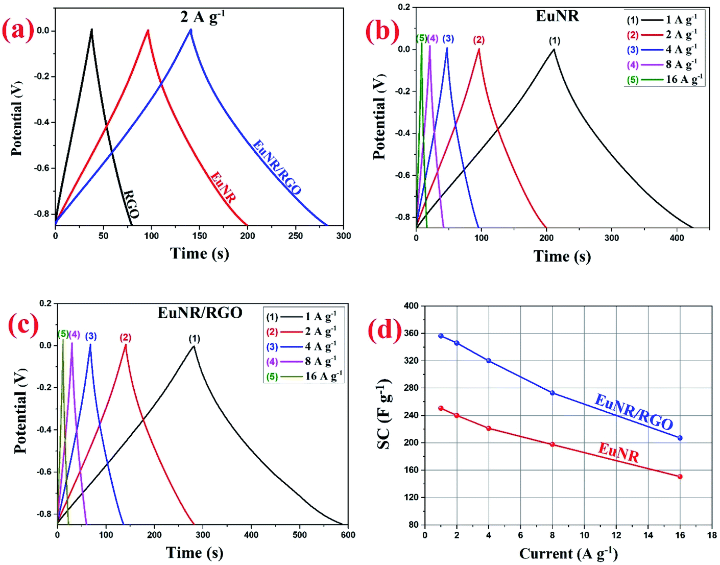 | ||
| Fig. 7 (a) RGO, EuNR and EuNR-RGO charge/discharge curves at 2.0 A g−1 current density; (b) EuNR charge/discharge curves at 1–16 A g−1 current densities; (c) EuNR-RGO charge/discharge curves at 1–16 A g−1 current densities and (d) EuNR and EuNR-RGO specific capacitance changes with changing current densities from 1 to 16 A g−1. | ||
In this equation, the discharge time (s), charge/discharge current (A) and potential drop (V) are represented by Δt, I and V, respectively.
In the case of EuNR-RGO, a particular capacitance of 345.9 F g−1 was achieved at 2 A g−1, which is the largest value among all other electrodes. Fig. 7b and c display the charge/discharge curves from 1 to 16 A g−1 current densities in the range from 0.1 to −0.9 V for both EuNR and EuNR-RGO. In both cases, the shapes of the curves are similar to an equilateral triangle, which implies reversibility and ideal capacitive behavior during the charge/discharge processes. Significant electrical conductivity raised from RGO and facilitated redox reactions due to the small size of Eu2O3 together with the accelerated charge transport achieved from the synergy between RGO and EuNR would be the reasons for the superior capacitive behavior of EuNR-RGO.49
Fig. 8 illustrates the superior performance of EuNR-RGO in comparison with the other electrodes, which was also confirmed by Ragone plots. The charge/discharge analyses at diverse current densities were used to calculate energy and power densities, which are necessary for this plot. At a power density of 425 W kg−1, the maximum energy density (i.e., 35.8 W h kg−1) was obtained for EuNR-RGO. In comparison to the other electrodes reported in literature, the gained value was very high.50–52 According to the energy and power densities, EuNR-RGO was considered as a suitable material for supercapacitor electrodes.
 | ||
| Fig. 8 Ragone plots of EuNR and EuNR-RGO. | ||
 | ||
| Fig. 9 Impedance spectra of EuNR and EuNR-RGO. The frequency range is 0.1–105 Hz. | ||
The equivalent circuit values are demonstrated in Table 1. It is clear that the value of Rct for EuNR-RGO is less than others. When Rct is less, it means that the electrochemical reaction is more facile at the electrode/electrolyte interface. Similarly, Table 1 illustrates that EuNR-RGO reveals enhanced electrochemical performance rather than EuNR. In addition, EuNR-RGO demonstrates more ideal Warburg resistance (more ideal capacitance behavior results in a more vertical line).57 As confirmed by chronopotentiograms and CVs, EIS further reveals synergism between EuNRs and RGO.
| EuNR | EuNR-RGO | |
|---|---|---|
| Rs (ohm) | 0.75 | 0.71 |
| Cdl (mF) | 2.75 | 2.12 |
| Rct (ohm) | 2.61 | 2.19 |
| ZW (mMho) | 540 | 603 |
| CF (mF) | 445 | 479 |
4. Conclusion
EuNR-RGO nanocomposites were synthesized by a facile sonochemical method, and the measurements indicated that the presence of RGO caused better conductivity by reducing the ionic mass-transfer resistance. Experiments proved that the SC, stability and energy density of the EuNR-RGO nanocomposite electrodes were superior to those of the electrodes based on pure RGO or Eu2O3. As a result, a composition of 1:1 wt of Eu2O3 nanorods to RGO caused the extraordinary supercapacitive behavior with an SC of about 403 F g−1 at a scan rate of 2 mV s−1. This was extremely superior in comparison to those of both the RGO and Eu2O3 nanorods. The CCV technique at 150 mV s−1 was used to investigate the nanocomposite electrode's stability. The SC of EuNR-RGO remained at almost 96.8% of its initial value after 5000 cycles. These data were further confirmed by EIS and galvanostatic charge/discharge. Therefore, the optimal EuNR-RGO nanocomposites are suitable materials for the construction of high-performance supercapacitor electrodes.
Conflicts of interest
There are no conflicts to declare.References
- A. Shiralizadeh Dezfuli, E. Kohan, H. R. Naderi and E. Salehi, New J. Chem., 2019, 43, 9260–9264 RSC.
- Z. S. Wu, G. Zhou, L. C. Yin, W. Ren, F. Li and H. M. Cheng, Nano Energy, 2012, 1, 107–131 CrossRef CAS.
- Y. Jahng, O. K. Kwon and S. Lee, Arch. Pharmacal Res., 2012, 35, 2199–2203 CrossRef CAS PubMed.
- Y. Wang, C. X. Guo, J. Liu, T. Chen, H. Yang and C. M. Li, Dalton Trans., 2011, 40, 6388–6391 RSC.
- H. R. Naderi, H. R. Mortaheb and A. Zolfaghari, J. Electroanal. Chem., 2014, 719, 98–105 CrossRef CAS.
- A. G. Pandolfo and A. F. Hollenkamp, J. Power Sources, 2006, 157, 11–27 CrossRef CAS.
- G. Wang, L. Zhang and J. Zhang, Chem. Soc. Rev., 2012, 41, 797–828 RSC.
- D. Joung, V. Singh, S. Park, A. Schulte, S. Seal and S. I. Khondaker, J. Phys. Chem. C, 2011, 115, 24494–24500 CrossRef CAS.
- B. Liu, L. Jiang, M. Yao, B. Liu, Q. Li, R. Liu, H. Lv, S. Lu, C. Gong, B. Zou, T. Cui, G. Hu and T. Wågberg, J. Phys. Chem. C, 2012, 116, 11741–11745 CrossRef.
- S. Yu, Q. Liu, W. Yang, K. Han, Z. Wang and H. Zhu, Electrochim. Acta, 2013, 94, 245–251 CrossRef CAS.
- H. Teymourian, A. Salimi and S. Khezrian, Biosens. Bioelectron., 2013, 49, 1–8 CrossRef CAS PubMed.
- Z. Ji, X. Shen, M. Li, H. Zhou, G. Zhu and K. Chen, Nanotechnology, 2013, 24, 115603 CrossRef PubMed.
- H. R. Naderi, M. R. Ganjali, A. S. Dezfuli and P. Norouzi, RSC Adv., 2016, 6, 51211–51220 RSC.
- A. S. Dezfuli, M. R. Ganjali, H. R. Naderi and P. Norouzi, RSC Adv., 2015, 5, 46050–46058 RSC.
- R. B. Rakhi, W. Chen, D. Cha and H. N. Alshareef, J. Mater. Chem., 2011, 21, 16197–16204 RSC.
- Q. Liao, N. Li, S. Jin, G. Yang and C. Wang, ACS Nano, 2015, 9, 5310–5317 CrossRef CAS PubMed.
- W. He, J. Lin, B. Wang, S. Tuo, S. T. Pantelides and J. H. Dickerson, Phys. Chem. Chem. Phys., 2012, 14, 4548–4553 RSC.
- B. Wang, J. Park, C. Wang, H. Ahn and G. Wang, Electrochim. Acta, 2010, 55, 6812–6817 CrossRef CAS.
- G. Adachi, N. Imanaka and Z. C. Kang, Binary rare earth oxides, Springer Netherlands, 2005 Search PubMed.
- M. P. Rosynek, Catal. Rev., 1977, 16, 111–154 CrossRef CAS.
- J. H. Jhang, A. Schaefer, W. Cartas, S. Epuri, M. Bäumer and J. F. Weaver, J. Phys. Chem. C, 2013, 117, 21396–21406 CrossRef CAS.
- S. Tsujimoto, T. Masui and N. Imanaka, Eur. J. Inorg. Chem., 2015, 2015, 1524–1528 CrossRef CAS.
- E. Antolini and J. Perez, Int. J. Hydrogen Energy, 2011, 36, 15752–15765 CrossRef CAS.
- E. Kohan and A. Shiralizadeh Dezfuli, J. Mater. Sci.: Mater. Electron., 2019, 30, 17170–17180 CrossRef CAS.
- D. A. Johnson, J. Chem. Educ., 1980, 57, 475–477 CrossRef CAS.
- H. Jafari, M. R. Ganjali, A. Shiralizadeh Dezfuli and E. Kohan, J. Mater. Sci.: Mater. Electron., 2018, 29, 20639–20649 CrossRef CAS.
- X. C. Song, E. Yang, R. Ma, H. F. Chen, Z. L. Ye and M. Luo, Appl. Phys. A: Mater. Sci. Process., 2009, 94, 185–188 CrossRef CAS.
- V. G. Pol, O. Palchik, A. Gedanken and I. Felner, J. Phys. Chem. B, 2002, 106, 9737–9743 CrossRef CAS.
- N. Du, H. Zhang, B. Chen, J. Wu, D. Li and D. Yang, Nanotechnology, 2007, 18, 065605 CrossRef.
- X. Wang and Y. Li, Chem.–Eur. J., 2003, 9(22), 5627–5635 CrossRef CAS PubMed.
- L. Zhang, H. Jiu, J. Luo and Q. Chen, J. Cryst. Growth, 2007, 309(2), 192–196 CrossRef CAS.
- L. Qian, Y. Gui, S. Guo, Q. Gong and X. Qian, J. Phys. Chem. Solids, 2009, 70, 688 CrossRef CAS.
- J. G. Kang, Y. Jung, B. K. Min and Y. Sohn, Appl. Surf. Sci., 2014, 314, 158–165 CrossRef CAS.
- D. C. Marcano, D. V. Kosynkin, J. M. Berlin, A. Sinitskii, Z. Sun, A. Slesarev, L. B. Alemany, W. Lu and J. M. Tour, ACS Nano, 2010, 4, 4806–4814 CrossRef CAS PubMed.
- P. Norouzi, T. M. Garakani and M. R. Ganjali, Electrochim. Acta, 2012, 77, 97–103 CrossRef CAS.
- A. Shiralizadeh Dezfuli, M. R. Ganjali and P. Norouzi, Mater. Sci. Eng., C, 2014, 42, 774–781 CrossRef CAS PubMed.
- A. S. Dezfuli, M. R. Ganjali, P. Norouzi and F. Faridbod, J. Mater. Chem. B, 2015, 3, 2362–2370 RSC.
- B. Liu, L. Jiang, M. Yao, B. Liu, Q. Li, R. Liu, Z. Yao, S. Lu, W. Cui, X. Hua, B. Zou and T. Cui, CrystEngComm, 2013, 15, 3739–3743 RSC.
- K. Huang, M. Lei, Y. J. Wang, C. Liang, C. X. Ye, X. S. Zhao, Y. F. Li, R. Zhang, D. Y. Fan and Y. G. Wang, Powder Diffr., 2014, 29, 8–13 CrossRef CAS.
- T. Yan, D. Zhang, L. Shi and H. Li, J. Alloys Compd., 2009, 487(1–2), 483–488 CrossRef CAS.
- A. S. Dezfuli, M. R. Ganjali, H. Jafari and F. Faridbod, J. Mater. Sci.: Mater. Electron., 2017, 28, 6176–6185 CrossRef CAS.
- P. G. Ren, D. X. Yan, X. Ji, T. Chen and Z. M. Li, Nanotechnology, 2011, 22(5), 55705 CrossRef.
- A. M. Jastrzębska, J. Karcz, R. Letmanowski, D. Zabost, E. Ciecierska, J. Zdunek, E. Karwowska, M. Siekierski, A. Olszyna and A. Kunicki, Appl. Surf. Sci., 2016, 362, 577–594 CrossRef.
- Y. V. Belokopytov, K. M. Kholyavenko and S. V Gerei, J. Catal., 1979, 60, 1–7 CrossRef CAS.
- H. Liu, X. Hu, H. Guo, J. Zhao, F. Li, D. Zhu and S. Liu, Phys. Chem. Chem. Phys., 2019, 21, 10947–10954 RSC.
- H. Jafari, M. R. Ganjali, A. Shiralizadeh Dezfuli and E. Kohan, J. Mater. Sci.: Mater. Electron., 2018, 29, 20639–20649 CrossRef CAS.
- Y. jing Yang, E. H. Liu, L. min Li, Z. zheng Huang, H. jie Shen and X. xia Xiang, J. Alloys Compd., 2009, 487, 564–567 CrossRef.
- H. Jafari, M. R. Ganjali, A. S. Dezfuli and F. Faridbod, Appl. Surf. Sci., 2018, 427, 496–506 CrossRef CAS.
- H. J. Choi, S. M. Jung, J. M. Seo, D. W. Chang, L. Dai and J. B. Baek, Nano Energy, 2012, 1, 534–551 CrossRef CAS.
- B. Li, Y. Fu, H. Xia and X. Wang, Mater. Lett., 2014, 122, 193–196 CrossRef CAS.
- X. Zhang, X. Sun, H. Zhang, D. Zhang and Y. Ma, Mater. Chem. Phys., 2012, 137, 290–296 CrossRef CAS.
- G. Yu, L. Hu, M. Vosgueritchian, H. Wang, X. Xie, J. R. McDonough, X. Cui, Y. Cui and Z. Bao, Nano Lett., 2011, 11, 2905–2911 CrossRef CAS PubMed.
- G. Wang, J. Zhang, S. Kuang, J. Zhou, W. Xing and S. Zhuo, Electrochim. Acta, 2015, 153, 273–279 CrossRef CAS.
- B. E. Conway, Electrochemical Supercapacitors, Springer US, 1st edn, 1999 Search PubMed.
- A. Zolfaghari, H. R. Naderi and H. R. Mortaheb, J. Electroanal. Chem., 2013, 697, 60–67 CrossRef CAS.
- K. Zhang, L. L. Zhang, X. S. Zhao and J. Wu, Chem. Mater., 2010, 22, 1392–1401 CrossRef CAS.
- L. Li, K. H. Seng, H. Liu, I. P. Nevirkovets and Z. Guo, Electrochim. Acta, 2013, 87, 801–808 CrossRef CAS.
| This journal is © The Royal Society of Chemistry 2020 |