
 Open Access Article
 This Open Access Article is licensed under a Creative Commons Attribution-Non Commercial 3.0 Unported Licence
Synthesis of monolithic shape-stabilized phase change materials with high mechanical stability via a porogen-assisted in situ sol–gel process†
Felix Marske a,
Juliana Martins de Souza e Silvab,
Ralf B. Wehrspohnb,
Thomas Hahna and
Dirk Enkec
a,
Juliana Martins de Souza e Silvab,
Ralf B. Wehrspohnb,
Thomas Hahna and
Dirk Enkec
aInstitute of Technical Chemistry, Martin Luther University of Halle-Wittenberg, 06108 Halle (Saale), Germany. E-mail: felix.marske@chemie.uni-halle.de
bInstitute of Physics, Martin Luther University of Halle-Wittenberg, 06108 Halle (Saale), Germany
cInstitute of Chemical Technology, Leipzig University, 04109 Leipzig, Germany
First published on 16th January 2020
Abstract
The confinement of phase change materials (PCMs) in construction materials has recently solved leakage, supercooling and low thermal conductivity problems in the industrial use of PCMs as monolithic thermal energy storage materials. To produce shape-stabilized PCMs (ss-PCMs) as crack-free monoliths, less than 15–30% v/v pure or encapsulated PCMs can be used in construction materials. Therefore, the heat storage capacity of these monolithic ss-PCM boards is comparatively low. In this study, we synthesized a novel class of monolithic ss-PCM boards with high compressive strength of 0.7 MPa at 30 °C (1.2 MPa at 10 °C), high PCM loadings of 86 wt%, and latent heats in the range of 100 J g−1 via a porogen-assisted in situ sol–gel process. We confined butyl stearate (BS) as PCM in a core-shell-like silica matrix via stabilized silica sol as silica source, sodium dodecyl sulfate as surfactant and poly(vinyl alcohol) as co-polymer. The ss-PCMs obtained are hydrophobic, thermally stable up to 320 °C and perform 6000 state transitions from solid to liquid and vice versa, without losing melting or freezing enthalpies. We analyzed the silica structure in the ss-PCMs to understand in detail the reasons for the high mechanical stability. The silica structure in ss-PCMs consists of spherical meso- and macropores up to 10![[thin space (1/6-em)]](https://www.rsc.org/images/entities/char_2009.gif) 000 nm filled with PCM, formed mostly by BS droplets in water as templates during gelation. With an increasing BS amount in the synthesis of ss-PCMs, the total nanopore volume filled with PCM in ss-PCMs increases, resulting in higher compressive strengths up to 500% and thermal conductivities up to 60%.
000 nm filled with PCM, formed mostly by BS droplets in water as templates during gelation. With an increasing BS amount in the synthesis of ss-PCMs, the total nanopore volume filled with PCM in ss-PCMs increases, resulting in higher compressive strengths up to 500% and thermal conductivities up to 60%.
1. Introduction
The worldwide primary energy demand is one of the greatest current problems of humanity. Since 1970, energy consumption and greenhouse emissions have increased by over 100%.1 Fossil fuels still produce nearly 85% of the worldwide energy, even though they are finite and have tremendous environmental impact.2 Therefore, the development of renewable energy sources and energy storage materials is imperative.3Thermal energy storage (TES) is an example of a promising energy storage concept, because it can store large amounts of energy as heat. It is typically divided into three groups: sensible heat storage (SHS), thermochemical heat storage (TCS) and latent heat storage (LHS).4
Most materials can store thermal energy in the form of sensible heat and the amount of stored energy depends on the specific heat capacity, mass and temperature change of the material.5 Sensible heat storage materials (SHS) have as major problems low energy densities and the sudden loss of energy to the environment at a temperature change. Thermochemical heat storage (TCS) materials are relatively novel and solely tested on a laboratory scale. They can store and release energy by reversible chemical reactions and show the highest energy density of all types of thermal energy storage materials.6 However, they present major disadvantages, such as slow heat and mass transfer from and to the storage volume, high investment costs, and complex reactor design that limits their application. In contrast, latent heat storage materials (LHS), also called phase change materials (PCMs), can store 5–14 times more heat per unit volume than sensible heat storage materials through a phase change at a nearly constant temperature.7 Moreover, they can conserve energy over a certain temperature for a long period and are used for a broad range of applications like energy-saving buildings,8 photovoltaics,9 textiles,10 and even solar cookers.11 Therefore, these materials fulfil the requirements for an adequate thermal energy storage material best.12
Their application, however, is limited by some drawbacks that are only partially under control.13 On one hand, inorganic PCMs, such as salts and hydrated salts, have excellent values of heat per unit volume, a suitable temperature range for the most promising applications in energy-saving buildings14 and concentrated solar power systems,15 besides good thermal conductivities. On the other hand, they suffer from supercooling and phase segregation.16 It should be mentioned that the solid–liquid phase change of salt hydrates occurs through a dehydration/hydration process, which is thermodynamically similar to the change of the aggregate state from solid to liquid. If the corresponding dehydrated salt is not completely soluble in its water of hydration, phase segregation occurs through incongruent melting. This leads to a decreased latent heat or, in the worst case, to a total loss of latent heat of the PCM after a few hydration/dehydration cycles.17 Some attempts to control supercooling by the addition of suitable nucleating agents are described in the literature,18,19 but the problem of phase segregation remains unsolved, and even various encapsulation techniques have not led to a solution.20
In contrast, organic PCMs, like paraffins and non-paraffins (n-alkanes, fatty acids, alcohols, polyethylene glycols), do not suffer from phase segregation or high supercooling effects, but are moderately flammable and have low thermal conductivities. Several studies attempted to address these two drawbacks of organic PCMs21 by the addition of 5–10 wt% of expanded graphite to the PCM, which results in an enhancement of the thermal conductivity of about 50–300%.8,22 The use of 2 wt% graphite in form of nanosheets can further increase the thermal conductivity of solid paraffins in a hybrid shell structure to 1 W m−1 K−1.23 To reduce the flammability of PCMs, melamine,24 tetrabromobisphenol-A25 and diethyl ethylphosphonate26 can be added. These components build a physical protective barrier around the PCM during combustion and limit the transfer of flammable molecules to the gas phase.
Generally, the leakage of liquid PCMs from construction materials must be prevented through the incorporation of the PCM in a suitable container, which can be a porous matrix or a core–shell structure. In recent years, the research focus shifted to micro- and nanoencapsulation of PCMs to produce core–shell PCMs (cs-PCMs), in which the core is composed by the PCM that is covered by a shell of an inorganic or organic polymer, forming particles of diameter in the micro- or nanoscale.27 The encapsulation method has several advantages, such as an increased heat transfer area, high encapsulation ratios of PCMs, less supercooling effects and a convenient handling for the later incorporation in construction materials like plaster, concrete or gypsum.28 The most prominent example for cs-PCMs is Micronal PCM (Microtek Laboratories, formerly by BASF). This cs-PCM consists of a paraffin core that is surrounded by a polyacrylate shell and has latent heats in the range of 100 J g−1.
However, the application of cs-PCMs like Micronal DS 5040 X is limited by the amount that can be later incorporated into construction materials to form monolithic shape-stabilized PCMs (ss-PCMs), which is 15% v/v for cementitious systems and 30% v/v for plaster-based systems.29 Moreover, the direct mixing of cs-PCMs or pure PCMs with construction materials, like concrete, leads to a drastic loss of the overall mechanical stability. As described by Hunger et al.,30 the compressive strength of concrete decreased from 74 MPa to 21 MPa by the addition of 5 wt% Micronal DS 5008 X. Similar results were already reported in the literature.31,32
Here, we report the synthesis of a novel class of monolithic shape-stabilized PCM boards that confined organic PCMs into nanopores, thus, allowing the addition of high mass fractions of PCMs by maintaining a high mechanical stability. To the best of our knowledge, studies to synthesize monolithic ss-PCMs in the literature failed mostly because of PCM leakage, loss of form-stability, or a low compressive strength.33,34 We have chosen butyl stearate (BS) as prototype for organic PCMs because of its superior properties, such as congruently melting and freezing, good thermal and chemical stabilities and non-toxicity,35 and immobilized it in a silica matrix via a novel in situ sol–gel process, which is assisted by a surfactant and an organic co-polymer. Stabilized silica sol was used as inexpensive silica source, cheaper than typically used precursors, like tetraethyl ortho-silicate.36 In contrast to methods like mini-emulsion polymerization, in situ sol–gel is an inexpensive one-pot synthesis and can be easily up scaled in a discontinuous batch reactor.37,38
2. Experimental
2.1. Materials
Köstrosol 0730 was used as stabilized silica sol (30 wt% colloidal silica particles in water, 7 nm average particle diameter) and provided by Chemiewerk Bad Köstritz, Germany. Butyl stearate (technical grade product) was obtained by Alfa Aesar. Sodium dodecyl sulfate (SDS, ≥99.0% GC, dust-free pellets) and poly(vinyl alcohol) (PVA, 88% hydrolyzed, average MW 22000) were purchased from Sigma-Aldrich and ACROS Organics, respectively. Deionized water was used for all experiments.
2.2. Preparation of monolithic ss-PCMs
The synthesis was carried out in polypropylene beakers. First, poly(vinyl alcohol) (PVA) was dissolved in water and heated to 60 °C for 3 h. Then, sodium dodecyl sulfate (SDS) and butyl stearate (BS) were added to the PVA solution, heated to 50 °C and left at this temperature for at least 6 h. The suspension was stirred with a magnetic stirrer for 15 min at 700 rpm and 25 °C. The stabilized silica sol was added dropwise to the suspension to start the sol–gel process and stirred for another 15 min at 700 rpm and 25 °C. Afterwards, the magnetic stirrer was removed, the beaker containing the reaction mixture was closed and heated to 40 °C for 2–3 days. The wet composite gel was dried at ambient pressure first at 40 °C for 4 days and then at 100 °C for 20 h. The synthetic route and synthesized ss-PCM monoliths are shown in Fig. 1 and Movies S1 and S2.† | ||
| Fig. 1 Schematic synthesis of monolithic ss-PCM with different sizes via in situ sol–gel. | ||
2.3. Characterization of the ss-PCM
The thermal and long-term performance of the ss-PCMs were characterized by DSC scans on an 822e calorimeter by METTLER TOLEDO with a heating rate of 1 °C min−1 as standard and 2 °C min−1 for the thermal cycling experiments in the DSC. The measurements were run from −20 °C to 60 °C under air atmosphere. The holding times at −20 °C and 60 °C were set to 10 min. Every sample was measured at least five times with the results being used to calculate the mean values for supercooling and latent heat. Differential thermal analysis and thermogravimetry (DTA/TG) were performed on a STA 409 C/CD thermal analyser by Netzsch to evaluate the thermal stability of the ss-PCMs.An amount of approximately 100 mg of the ss-PCMs and the pure PCM were heated-up from room temperature to 700 °C with a heating rate of 10 °C min−1 and 1 °C min−1 under air atmosphere.
The connectivity of the silica phase was analysed via High Power Decoupling (HPDEC) Magic Angle Spinning (MAS) 29Si NMR on a Bruker DRX-400 WB NMR spectrometer (Bruker Biospin, Karlsruhe, Germany) equipped with a 4 mm double-resonance MAS probe maintained at 10 °C by a temperature control unit. All spectra were recorded at a Larmor frequency of 79.49 MHz, acquired at a spinning speed of 12 kHz and a recycle delay of 40 s, and referenced externally to tetramethylsilane (TMS). For the measurements, the samples were scanned 256 times at a radio-frequency field strength of 42 kHz as a π/2 pulse during an acquisition time of 25 ms.
To analyze the mechanical properties of the ss-PCMs, five samples were synthesized with the same chemical composition and their compressive strength was tested on a TBH355 hardness tester by ERWEKA to calculate a mean value. The five measurements were performed at 10 °C and 30 °C for the compressive strength of the solid and liquid PCM in the solid ss-PCM. The hydrophobicity of the ss-PCMs was characterized by contact angle measurements with water on an OAC 15EC drop shape analyzer by DataPhysics. A Seven Easy pH electrode by METTLER TOLEDO was used to measure the pH value of the solution at room temperature.
The macroporosity of the ss-PCMs and silica matrix were analyzed by mercury (Hg) intrusion measurements on Pascal140 (400 kPa) and Pascal440 (400 MPa) instruments (Porotec). An amount of approximately 80–100 mg of the samples was used for each measurement. The micro- and mesopore structures of the silica phase in ss-PCMs were characterized by nitrogen sorption measurements at −196 °C using a Sorptomatic 1990 surface area analyzer (Porotec). An amount of approximately 100–150 mg of each sample was analysed before and after the calcination of the ss-PCM at 600 °C (10 h). The specific surface area of the ss-PCM was calculated via the Brunauer–Emmett–Teller (BET) method. The ss-PCMs were imaged on a Leo Gemini 1530 Zeiss scanning electron microscope. For the preparation, the samples were placed on a conductive carbon tape. The secondary electrons were accelerated to a voltage of 10 kV during the measurement.
X-ray imaging experiments were performed in a Carl Zeiss Xradia 810 Ultra (Cr X-ray source, 5.4 keV). Absorption-based and phase-contrast imaging experiments were performed. For the later, a Zernike phase-ring was positioned near the back focal plane of the zone plate. In the imaging experiments, a total of 901 projections with a field-of-view (FOV) of 65 × 65 μm2 were obtained over 180°, with an exposure time of 30 s per projection, a detector binning of 2 and the voxel size of 128 × 128 × 128 nm3 in the final images. Image reconstruction was performed by filtered back-projection algorithm using the software integrated into the Xradia 810 Ultra. Commercial software Thermo Scientific Avizo was used for image correction segmentation, and 3D renderings presented here. Pore segmentation was done after separation of the main structure from the pores, application of the “separate objects” module using the maximum number of seeds for the watershed algorithm therefore applied. Volumes used for the small pore calculations had a minimum value of 0.14 μm3, corresponding approximately to a sphere with about 2.5 voxels of radius. Results presented here were obtained after performing calculations over volumes of 325 × 325 × 325 voxels.
The thermal conductivity was measured with a Hot Disk TPS 1500 thermal analyzer by Hot Disk AB in sandwich-mode. First, the monolithic sample was sawed through the middle. The thermal sensor was then covered by the two pieces (sandwich-mode) and measured the thermal conductivity five times after 30 minutes. The average value was calculated.
3. Results and discussion
3.1. Development of an in situ synthesis for monolithic ss-PCMs
We aimed to synthesize five different ss-PCMs, named here FS1 to FS5, via in situ sol–gel process by varying the amounts of butyl stearate (BS), sodium dodecyl sulfate (SDS) and polyvinyl alcohol (PVA) (Table 1). SDS and PVA were used to stabilize the O/W-emulsion via creation of micelles and to increase the viscosity of the reaction mixture. The quality of the obtained ss-PCMs was characterized by form-stability and compressive strength tests. The form-stability of ss-PCMs is typically characterized by a simple PCM leakage test at higher temperatures.39 The PCM leakage (wt%) was calculated by the percentage mass difference of the sample before and after heat treatment for 24 h at 100 °C.| Sample | PVA (g) | SDS (g) | BS (g) | pH | GP (h) | σ (MPa) at 10 °C/30 °C |
|---|---|---|---|---|---|---|
| FS1 | 0.0 | 0.0 | 0–20.0 | 9.6 | — | — |
| FS2 | 0.6 | 0.0 | 0–20.0 | 7.3 | — | — |
| FS3 | 0.0 | 0.8 | 20.0 | 10.5 | 33.0 | 0.006/0.002 |
| FS4 | 0.6 | 0.8 | 20.0 | 9.2 | 29.0 | 1.2/0.7 |
| FS5 | 1.0 | 0.8 | 16.5 | 8.9 | 7.0 | 0.8/0.5 |
For the samples FS1 and FS2, synthesized without SDS as emulsifier, the reaction mixture separates in a hydrophobic butyl stearate phase and a hydrophilic water phase after stirring. Gelation of the stabilized silica sol is initiated with the addition of at least 20 wt% BS to the reaction mixture, in contrast to what is observed for the addition of tetraethyl orthosilicate.38,40,41 To increase viscosity of the O/W-emulsion, we have added PVA to the reaction mixture of FS1, forming FS2 (Table 1). The subsequent gelation process is not only accelerated, but can start even without the addition of BS, because of a reduced pH value (9.6 to 9.0).
To enable the stabilization of BS in water and prevent the phase separation observed for FS1 and FS2, we have added SDS to the synthesis of FS3 and FS4. FS3 (without PVA) is form-stable and no leakage of BS is observed at 100 °C. However, FS3 is not monolithic and has a poor compressive strength of 2 kPa at 30 °C and 6 kPa at 10 °C.
In contrast, FS4 with PVA as co-polymer and SDS as surfactant, is not only form-stable, but also monolithic and shows higher values for compressive strength of ss-PCMs (0.7 MPa at 30 °C, 1.2 MPa at 10 °C) with similar PCM mass fractions than found in the current literature (mostly in the range of 10 kPa) (Fig. 2(a)).42 Additionally, FS4 shows no macroscopic cracks despite a high effective mass fraction Ma(PCM) of 83 wt%, which was calculated by eqn (1) and (2).
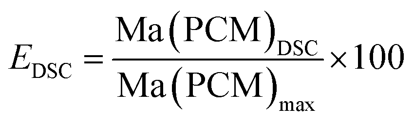
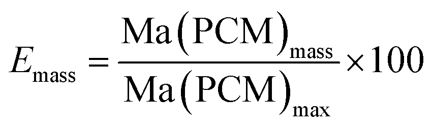
 | (1) |
 | (2) |
 | ||
| Fig. 2 Picture (a) and contact angle measurement of sample FS4 (b). | ||
We are currently investigating the complex role of SDS and PVA and expect, that SDS forms micelles around BS droplets and stabilize them in gelation process, whereas PVA should induce phase separations for pore channels necessary for a break-free drying process of ss-PCM xerogels.
By varying the amount of BS (70–94 wt%) in the synthesis of sample FS4, monolithic (FS470–FS486) and form-stable ss-PCMs (FS470–FS494) were synthesized (Fig. 3). The compressive strength increases for FS470 to FS478 and decreases for FS478 to FS486 by increasing the BS amount used for the synthesis, indicating that BS amounts lower than 78 wt% have a stabilizing function in sol–gel process. However, they were not analysed further since compressive strength improved only marginally compared to FS4 while lowering the BS amount.
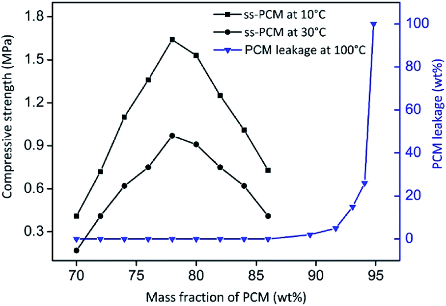 | ||
| Fig. 3 Mechanical stabilities and PCM leakage (100 °C, 24 h) tests of ss-PCMs FS470–FS494. The subscripts encode the amount of BS used for the synthesis. The ss-PCMs are form-stable up to 94 wt% BS and monolithic up to 86 wt% BS as PCM. | ||
In general, a high density of ss-PCM FS4 is desirable to store more heat in a smaller volume of the silica matrix. Therefore, we calculated the density of the sample by measuring the weight and the dimensions of the cylindrical monolith FS4.
The density of sample FS4 is 0.07 g cm−3 higher than the density of pure butyl stearate (0.86 g cm−3). This is due to a high shrinkage of FS4 as wet gel (approximately 35% v/v during drying).
We analyzed the hydrophobicity of FS4 via contact angle measurement with water (Fig. 2(b)), as an indication of the weatherability of this ss-PCM. Weatherability is an important factor for the use of ss-PCMs in construction applications. The contact angle of 101° (>90°) indicates that FS4 is hydrophobic, pointing to a good weatherability. In 29Si MAS NMR studies (Fig. 4), the peaks observed for the silica matrix in FS4 shows (Si–O)2Si(O–Si)2 species at −111 ppm (Q4) with the highest peak intensity, followed by (Si–O)2Si(O–Si)(OH) species at −102 ppm (Q3) and (Si–O)2Si(OH)2 species at −92 ppm (Q2) with much lower peak intensities. Therefore, the complete silica phase is condensed without free silica particles left in the ss-PCM, which should be one reason for the high mechanical stability of FS4. Additionally, the hydrophobicity of FS4 is based on the hydrophobic nature of butyl stearate without covalent Si–O–C- or Si–C-bonds between silica and BS, PVA or SDS. The BS has only weakly attractive interactions to the silica phase due to its ester function. Thus, BS is not able to build Si–O–C- and Si–C-bonds with the silica phase under the mild synthesis conditions in this work (Fig. 4).
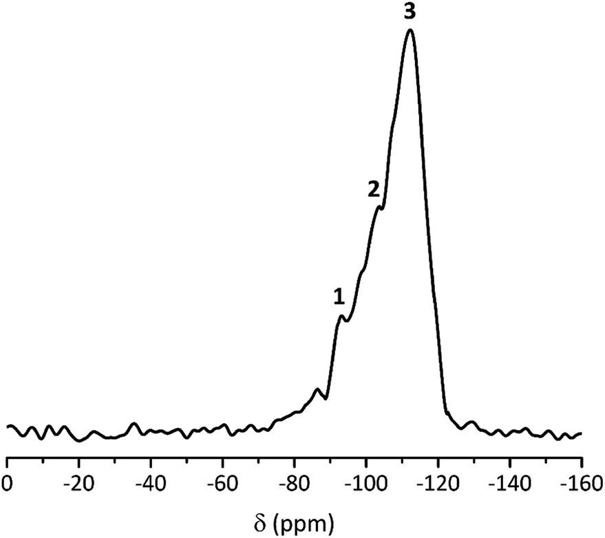 | ||
| Fig. 4 29Si MAS NMR spectrum of ss-PCM FS4: 1 = (Si–O)2Si(OH)2 (Q2); 2 = (Si–O)2Si(O–Si)(OH) (Q3); 3 = (Si–O)2Si(O–Si)2 (Q4). | ||
3.2. Thermal properties of ss-PCMs
The compressive strength of 0.7 MPa (30 °C), the monolithic shape and the hydrophobic nature of FS4 makes this sample a promising thermal energy storage board that does not need to be incorporated into concrete like other cs-PCMs.29,30,32 However, PCMs often suffer from supercooling effects and low latent heats after confinement.7 For this reason, we compared the freezing and melting enthalpies of BS (technical grade) and the sample FS4 via DSC measurements (Fig. 5). The peaks observed for BS below 10 °C occur due to impurities of the technical product, with latent heats of approximately 20 J g−1. The melting and freezing points of BS, respectively at 21.7 °C and 17.6 °C, shift to lower temperatures after its confinement in the porous silica matrix in case of sample FS4. Additionally, the freezing point of FS4 decreases by 0.7 °C more than the melting point, resulting in a slightly increased supercooling. According to literature, supercooling of confined PCMs depends on thermal conductivity, pore size of the silica matrix filled with PCM and interactions between pore surface and PCM.43 Here, FS4 has a higher thermal conductivity (0.22 W m−1 K−1, 30 °C) than pure butyl stearate (0.12 W m−1 K−1, 30 °C), which should accelerate the heat transfer of the sample FS4 during state transition and shifts the melting and freezing points to lower temperatures. In contrast, the pore size effect (described via Clapeyron equation)44 leads to an increased melting point, because of the increased pressure in the ss-PCM structure induced by capillary forces, and should occur in pore structures with smaller micro- and mesopores. Finally, the hydrophobic BS can build just weakly attractive interactions with the silica surface (Fig. 4), which should result in lower melting and freezing points according to the literature.43,45,46 In this work, the accelerated heat transfer and the weak attractive interactions between silica surface and PCM should be the dominant effects for the decreased freezing and melting points of FS4 (Fig. 5). Thus, we expect that the pore structure of the silica phase in FS4 mainly consists of macropores.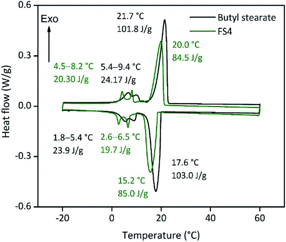 | ||
| Fig. 5 DSC curves of butyl stearate and FS4. | ||
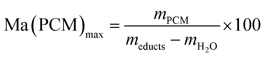
The effective mass fraction of PCM Ma(PCM) is an important parameter to characterize the storage capacity of the silica matrix and to calculate the efficiency E of the PCM confinement. The efficiency E measures the percentage of PCM (%) immobilized in the dried xerogel after synthesis. The effective mass fractions Ma(PCM) and the confinement efficiency E of FS4 were calculated by weight (mass) and DSC using eqn (1)−(5).
 | (3) |
 | (4) |
 | (5) |
Generally, effective mass fractions are calculated by melting enthalpies of ss-PCM and pure PCM in literature (eqn (1)). If, however, FS4 is measured at different parts of the sample via DSC, the melting enthalpies and calculated effective mass fractions vary: parts from the middle section of the sample vary over a range of 80–87 wt%. From top to bottom sections, they vary by approximately 13 wt% and from the sides the variation is about 9 wt% (Fig. 6). Consequently, BS must be distributed inhomogeneously in the xerogel structure and is accumulated mostly in the bottom part of the monolith FS4. For a more accurate calculation of effective mass fractions, we weighed our ss-PCMs and used the eqn (2) to calculate the effective mass fraction Ma(PCM)mass. The value of Ma(PCM)mass differs by only 0.5 wt% from the average Ma(PCM)DSC of FS4 (ØMa(PCM)DSC) (Fig. 6). To validate our data, we compared the value of Ma(PCM)mass with Ma(PCM)max, which corresponds to the maximal immobilized amount of PCM in ss-PCMs (eqn (3)). Because both values are identical, the simple weighing seems to be an appropriate method to determine the exact effective mass fraction of PCM in ss-PCMs. Moreover, the identical values of Ma(PCM)mass, Ma(PCM)DSC and Ma(PCM)max indicate a 100% confinement of PCM in FS4 (eqn (4) and 5). However, the ss-PCM must be fully dried to calculate Ma(PCM)mass (eqn (2)).
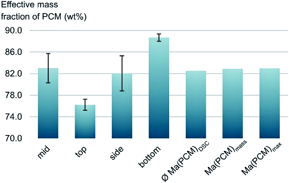 | ||
| Fig. 6 Effective mass fractions of PCM from the mid, the side, the bottom and the top of ss-PCM FS4 and the average value from DSC ØMa(PCM)DSC compared to Ma(PCM)mass and Ma(PCM)max (eqn (1)−(3)). | ||
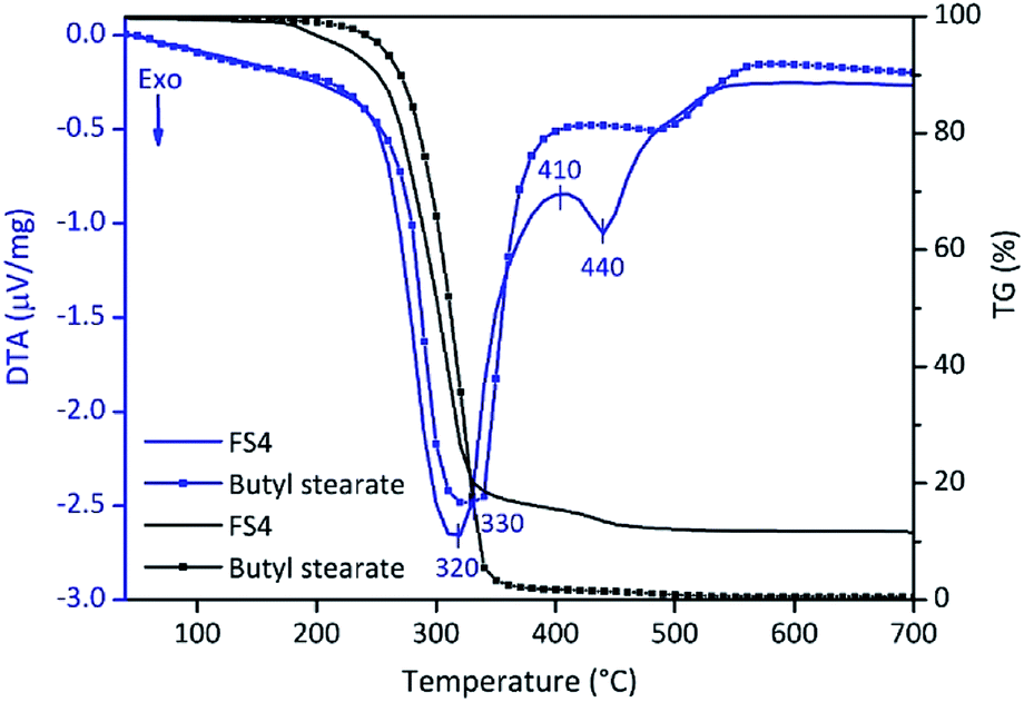
In summary, the high latent heats and confinement efficiencies besides a low supercooling effect enables the economically feasible use of FS4. However, the application range of FS4 is limited to its thermal stability. For this reason, we investigated the thermal stability of FS4 and pure BS by DTA/TG (Fig. 7). A 4 wt% weight loss is observed for FS4 between 100–200 °C and should be related to the decomposition of SDS and dehydration of PVA.47,48 The 80 wt% weight loss of FS4 at 320 °C should be related to the removal of BS. Pure BS evaporates at 330 °C, and confined BS in the sample FS4 at 320 °C, probably due to the higher thermal conductivity of FS4. At higher temperatures, PVA and high-molecular degradation products of BS completely decompose.48 Finally, only silica (12 wt%) remains after heating FS4 up to 700 °C.
 | ||
| Fig. 7 DTA/TG curves of FS4 and pure butyl stearate (heating rate: 10 °C min−1). | ||
3.3. Long-term performance of ss-PCMs
Encapsulated PCMs often loose melting and freezing enthalpy after some state transitions, due to possible reactions with matrix or capsule, which can be detrimental for future low temperature applications.19,49 For this reason, we tested the long-term performance of our ss-PCM via DSC in a thermal cycling experiment (Fig. 8). Each state transition from solid to liquid and vice versa was marked as one cycle. The amount of PVA and BS of FS4 was changed slightly for this experiment to shorten the gelation time from 29 to 7 h and increase the homogeneity of the PCM distribution in the ss-PCM by the higher viscosity of the system during gelation. The corresponding sample was named FS5 (Table 1) and was measured over 6000 times via DSC (Fig. 8). The melting enthalpies of all measurements remain similar to the value of the first cycle, with 80.4 ± 0.67 J g−1 (standard variation of the DSC device). The sample FS5 has therefore no important decrease of melting or freezing enthalpies even after 6000 cycles. Thus, FS5 does not react irreversibly with the chemical additives, such as PVA and SDS, in the ss-PCM during state transition, which is in accordance with the results of 29Si MAS NMR studies (Fig. 4). In the current literature, ss-PCMs and cs-PCMs are usually tested for no more than approximately 1500 cycles.49–51 For this reason, sample FS5 has a very high long-term performance. This result is relevant for the possible application of FS5 in building walls, because the durability of a PCM is directly related to its long-term performance.49,51 In the long-term performance test (Fig. 8), each cycle corresponds to freezing in a cold night and melting in a warm day in a composite wall. According to this definition,51 the ss-PCM FS5 is stable over 16 years in building walls. In several studies, building walls impregnated with approximately 30 wt% organic PCM and a thickness of 10–20 mm could lead to 2–3 GJ year−1 energy-saving, resulting in an amortization period of 9–18 years.52 Because FS5 has 79 wt% PCM, we expect a much shorter amortization period of FS5 as energy-saving walls in buildings.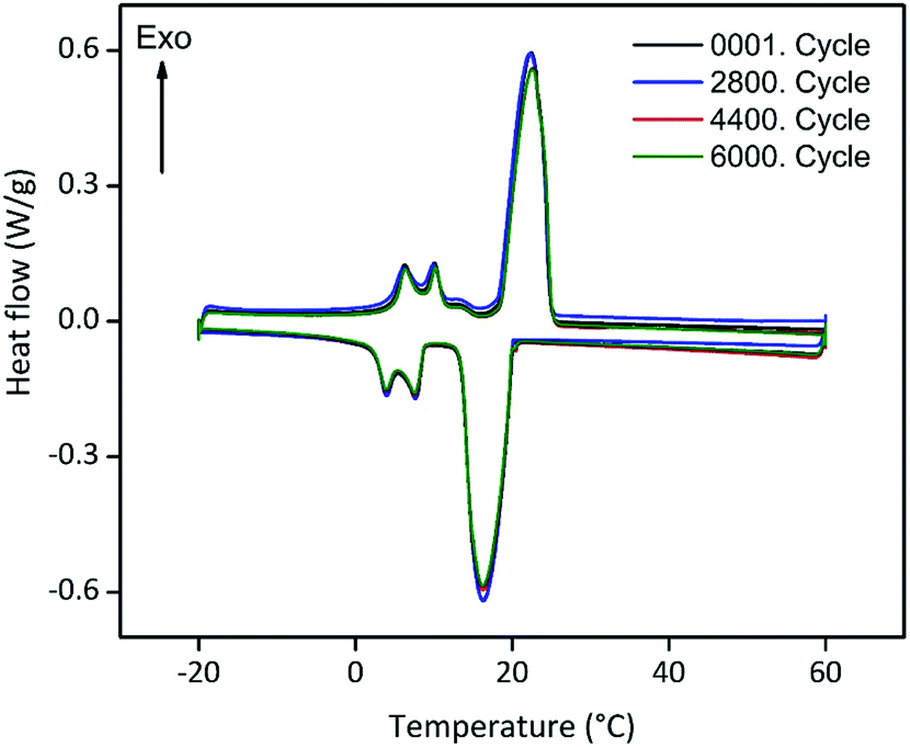 | ||
| Fig. 8 Long-term performance tests for sample FS5. The sample was melted and freezed up to 6000 times (6000 cycles) via DSC measurements with a heating rate of 2 °C min−1 to check for a possible decrease of the phase change enthalpy and, thus, the durability of the ss-PCM FS5. | ||
3.4. Silica structure in ss-PCMs
Our ss-PCMs FS4 and FS5 show superior characteristics for application as thermal energy storage board in buildings, such as higher mechanical stabilities (1–2 MPa), long-term performances (stable over 6000 thermal cycles) and higher thermal conductivities (83% higher than BS) than ss-PCMs reported in the current literature.49,53,54To understand the better performance of these samples, we first analysed the structure of the silica phase in five ss-PCMs prepared according to the synthesis of FS5, with a BS amount of 10.0 g (FS5100) to 20.0 g (FS5200) (Table 2 and Fig. 9). Then, we compared the silica structures of FS5200 with the silica structure of sample FS4 to investigate the influence of the PVA amount used for the synthesis (Table 1). We calcined also FS5100–FS5200 and FS4 at 600 °C for 6 h (FS5c100–FS5c200 and FS4c) to be able to distinguish the silica pores filled with air from the silica pores filled with PCM. No remaining organic substances were detected after calcination by FTIR spectroscopy (Fig. S1†).
| Sample | Φb,c (%) | Vtotalb,c (cm3 g−1) | Vmacrob (cm3 g−1) | Vmesoc (cm3 g−1) | Dmacrob (nm) | Dmesoc (nm) | Amesoc (m2 g−1) | σ (MPa) at 10 °C/30 °C | TD (°C) |
|---|---|---|---|---|---|---|---|---|---|
| a Porosity Φ, total pore volume Vtotal, macropore volume Vmacro, mesopore volume Vmeso, mean macropore diameter/50% Dtotal, mean mesopore diameter/50% Dmeso, mesopore surface area Ameso, compressive strength σ and decomposition point of BS in ss-PCMs (heating rate: 1 °C min−1).b Calculated via mercury intrusion.c Calculated via nitrogen sorption. | |||||||||
| FS5100 | 57 | 0.60 | 0.60 | — | 20036 |
— | — | 0.3/0.1 | 200 |
| FS5125 | 53 | 0.51 | 0.51 | — | 10980 |
— | — | 0.5/0.3 | 209 |
| FS5150 | 17 | 0.09 | 0.09 | — | 5863 | — | — | 1.1/0.6 | 223 |
| FS5175 | 10 | 0.05 | 0.05 | — | 14334 |
— | — | 0.9/0.5 | 215 |
| FS5200 | 5 | 0.02 | 0.02 | — | 235 | — | — | 0.8/0.4 | 216 |
| FS4 | 5 | 0.03 | 0.03 | — | 250 | — | — | 1.2/0.7 | 216 |
| FS5c100 | 92 | 5.35 | 4.81 | 0.54 | 4031 | 8 | 211 | — | — |
| FS5c125 | 93 | 5.67 | 5.10 | 0.57 | 4390 | 8 | 212 | — | — |
| FS5c150 | 92 | 5.34 | 4.78 | 0.56 | 2824 | 8 | 202 | — | — |
| FS5c175 | 94 | 6.64 | 6.09 | 0.55 | 1493 | 8 | 200 | — | — |
| FS5c200 | 95 | 8.12 | 7.46 | 0.66 | 1460 | 9 | 213 | — | — |
| FS4c | 95 | 7.80 | 6.98 | 0.82 | 1007 | 8 | 181 | — | — |
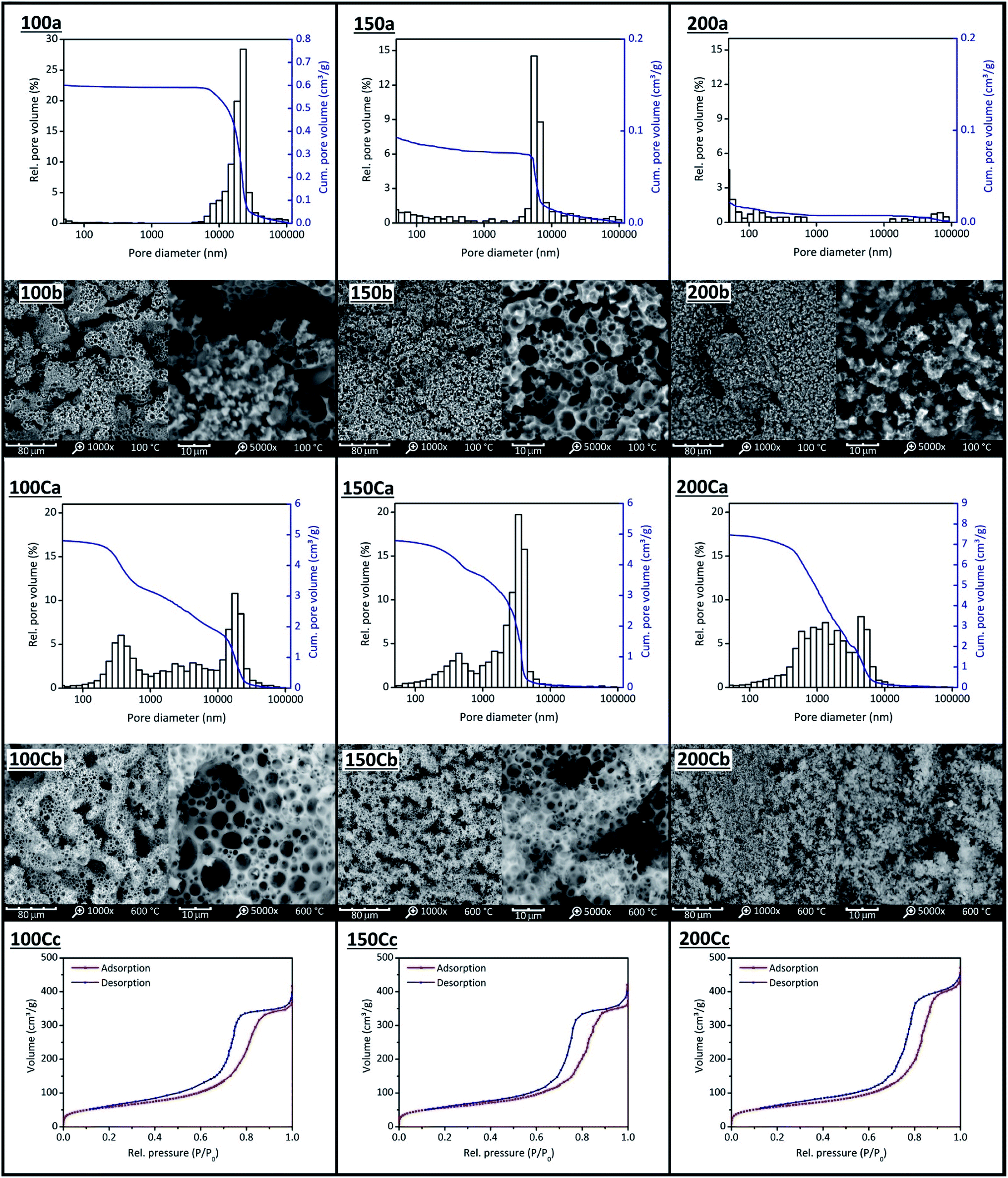 | ||
| Fig. 9 Mercury intrusion measurements (a), SEM images (b) and nitrogen sorption isotherms (c) of FS5100(100) to FS5200 (200) and FS5c100(100C) to FS5c200(200C). The amount of BS was increased from 10.0 g (FS5100) to 20.0 g (FS5200) and the ss-PCMs calcined (C) at 600 °C for 6 h to identify silica pores filled with air from silica pores filled with PCM. | ||
We analysed the mesopores only with nitrogen sorption (N2) because the high pressure of Hg intrusion (≤400 MPa) could decompress BS and destroy silica structures in ss-PCMs. The isotherms of FS5c100–FS5c200 are type IV isotherms with H1/H2 hysteresis, typical for mesoporous materials (Fig. 9(c)). Micropores were not detected for FS5c100–FS5c200 by N2 sorption. The mesopore volume of FS5100–FS5200 should be completely filled with PCM because N2 sorption experiments show no N2 sorption. The BS amounts above 17.5 g increase the mesopore volume slightly from 0.55 cm3 g−1 for samples FS5c175 to 0.66 cm3 g−1 for FS5c200, whereas the BS amount below 17.5 g does not affect the mesopore volume of the ss-PCMs FS5c100–FS5c175.
When the total pore volumes are compared (Table 2), two specific effects are observed. First, the total pore volumes of FS5c100–FS5c150 are similar and around 5 cm3 g−1, even though the BS amount used for the synthesis is increased. Second, the total pore volume increases from 5.34 cm3 g−1 to 8.12 cm3 g−1 for FS5c150–FS5c200, indicating a change of the templates for the pore structure during gelation. Pure and emulsified BS droplets alongside water and air bubbles covered by SDS can act as templates for the silica pore structure during gelation. The total pore volume of FS5c100 (similar to FS5c125 and FS5c150) must be caused by foam pores (air inclusions) with diameter above 10000 nm (Fig. 9(C)). These “wormlike” pores of FS5100 and FS5c100 (Fig. 9(C)) have total pore volumes of 0.54 cm3 g−1 and 1.8 cm3 g−1.
With an increasing amount of BS, the pore volume above 10000 nm is decreased to nearly zero for samples FS5150 and FS5c150 (Table 2). Moreover, the pore volume between 2000–10000 nm of FS5c150 increases by nearly 1.8 cm3 g−1, whereas the pore volume between 2–2000 nm is nearly constant for FS5c100–FS5c150 (2 cm3 g−1). For this reason, the pores between 2–2000 nm and 2000–10000 nm must be formed by different template types.
Because the interfacial tension of SDS micelles filled with oil is quite lower than those filled with air,55 SDS micelles filled with oil (BS) are smaller and require less work W to be formed in emulsions, according to eqn (6).56
| W = γΔA | (6) |
At a constant SDS amount, the increasing BS amount from FS5100 to FS5150 leads to more oil phase during gelation, that requires less work to be covered by SDS molecules than air inclusions. Simultaneously, the amount of SDS molecules in solution, which can form micelles with air (foam pores), decreases. Finally, all SDS molecules cover BS droplets in solution. This is the case for FS5150 without foam pores above 10000 nm (Fig. 9 (150b)) and results in a decrease of the mean macropore diameter from 4031 nm for FS5c100 to 2824 nm for FS5c150. Because the pore volume between 2000–10000 nm of FS5c100–FS5c150 changed by adding BS (Fig. 9 (100Ca and 150Ca)), the pores must be formed by BS droplets covered by SDS molecules. In SEM images, not only the pores between 2000–10000 nm are spherical, but also the pores between 2–2000 nm, indicating spherical template arrangement (Fig. 9 (100Cb and 150Cb)). These spherical templates should be the reason for the increase in the total pore volume of FS5c150–FS5c200 from 5.34 cm3 g−1 to 8.12 cm3 g−1. Because the pore volume of pores between 2000–10000 nm of samples FS5c150–FS5c200 (2.6 cm3 g−1) is nearly constant, the spherical templates should be pure BS droplets in water.
In general, the spherical pores from 2–10000 nm are located on pore bridges (Fig. 9 (100Cb–200Cb)). With a BS amount above 15.0 g, the pore bridges start to fragment and loose connectivity, resulting in a decrease of the overall mechanical stability from 0.6 MPa for FS5150 to 0.4 MPa for FS5200 (Fig. 9 (150Cb and 200Cb)). Additionally, the compressive strength of FS5100 is 0.5 MPa lower than FS5150 due to foam pores above 10000 nm indicating the influence of templates on the mechanical stability of ss-PCMs.
For the TGA measurements of FS5100 to FS5200 (Table 2, Fig. S8 and S9†), the heating rate was reduced from 10 °C min−1 to 1 °C min−1 for a higher sensitivity, resulting in lower decomposition points for BS of 218 °C instead of 330 °C (Fig. 7 and S9†). The decomposition point of BS in sample FS5150 is 20 °C higher and 5 °C lower than for samples FS5100 and FS5200 due to the higher interconnectivity of silica particles in FS5150 (Table 2 and Fig. S8†). Thus, the interconnectivity of the silica structure directly influences the mechanical and thermal stability of the ss-PCMs. The confinement efficiencies EDSC and Emass (eqn (4) and (5)) for FS5100 to FS5200 are all nearly 100%, indicating no influence of the pore structure on the melting enthalpies (Table S1†). The supercooling increases from 3.3 °C for FS5100 to 5.3 °C for FS5200 because of the increasing mass of the low thermal conductive BS (Table S1 and Fig. S10†). In contrast to FS5c200, sample FS4c has a higher mesopore volume of 0.82 cm3 g−1 and a smaller mean macropore diameter of 1007 nm (Table 2 and Fig. S2†). Moreover, FS4 and FS4c have a less fragmented spherical pore structure compared to FS5c200 and FS5200 (Fig. 9 (200b and 200Cb) and 10(A−C)).
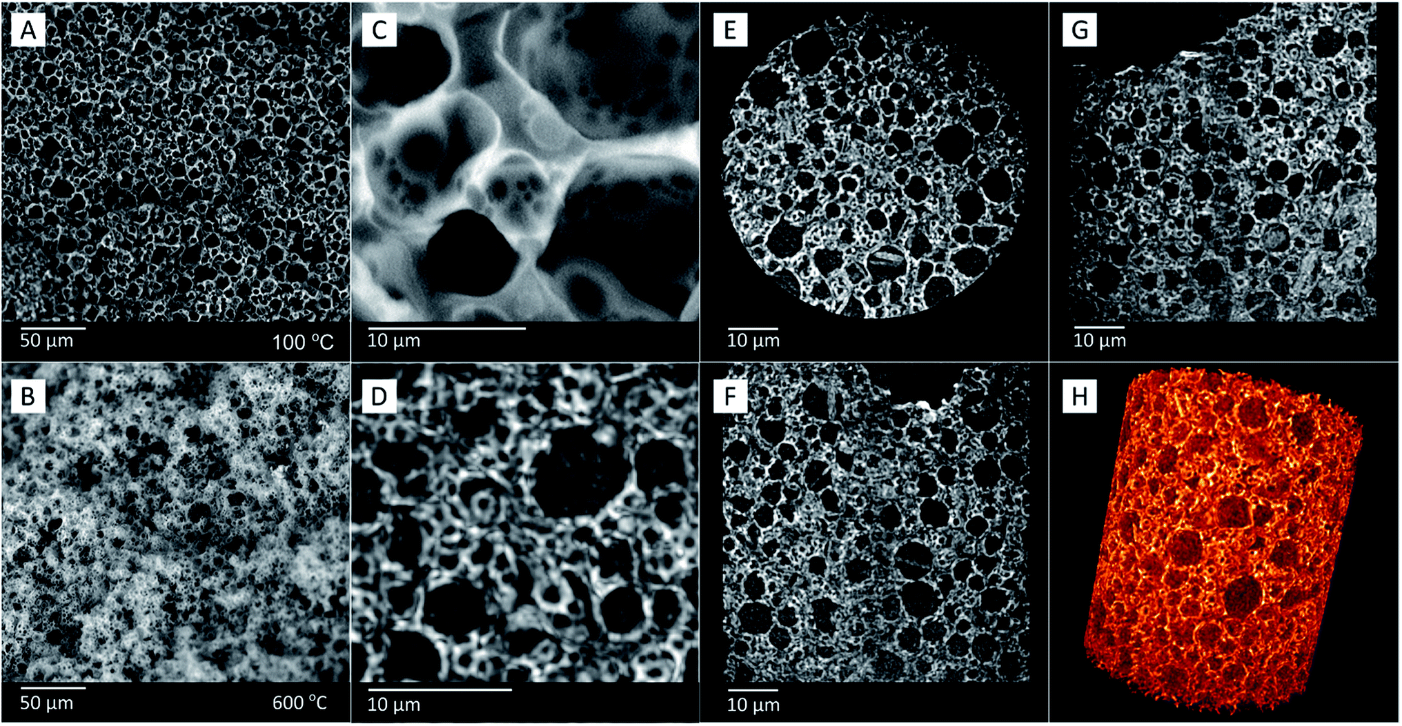 | ||
| Fig. 10 SEM images of sample FS4, showing its morphology (A) before and (B) after calcination (FS4c). Comparison of (C) SEM and (D) corresponding X-ray images of sample FS4c, showing similar features in higher-resolution. Image (D) shows the sum of a number of XRM 2D images, to give the same impression of depth as SEM images. Images of three different planes (E–G) of sample FS4c obtained by X-ray imaging, and (H) the respective volumetric representation of the sample obtained by XRM. | ||
In contrast to mercury intrusion (Table 2 and Fig. S2†), the SEM images of sample FS4c show spherical macropores with pore diameters of up to 8000 nm (Fig. 10(B)). This contrast should result from the limitations of the mercury intrusion technique.
We have analyzed the silica phase of sample FS4 via the sensitive three-dimensional (3D) high-resolution X-ray transmission microscopy (XRM) to visualize the macropores filled with PCM without calcination of the ss-PCM. Because the SEM images of FS4c are comparable to the 3D XRM images of FS4 (Fig. 10(C and D), the calcination of FS4 at 600 °C should have only a small impact on the pore structure of the silica structure in the ss-PCM.
Additionally, the 3D XRM images and movies (Fig. 10(D−H) and Movie S3 and 4†) indicate in accordance with the results of 29Si MAS NMR measurements (Fig. 4) a homogenous distribution of the silica phase in sample FS4 monolith without cracks or fragmented silica particles over a larger length scale in all three dimensions. The well interconnected silica particles in the ss-PCM should be the reason for the high compressive strength of FS4 (0.7 MPa, 30 °C).
We expect that the lower PVA amount in FS4 affected the size and the connectivity of the micelles filled with BS and of the BS droplets through a polymer-induced phase separation during gelation. This assumption would explain the different pore structures and compressive strengths of FS4 and FS5200.
In comparison to similar ss-PCM studies, the pores of samples FS4 and FS5 filled with PCM prepared in this work are relatively small, with a more interconnected silica phase.41,53,57 The compressive strength and thermal conductivity increase with a decreasing macropore diameter from FS5100 (0.1 MPa, 0.12 W m−1 K−1) to FS5150 (0.6 MPa, 0.20 W m−1 K−1). Higher amounts of BS (FS5200) result in widening of the macropores and, thus, a decrease in the compressive strength (0.8 MPa) and the thermal conductivity (0.18 W m−1 K−1 ) of the sample, which is similar to recent studies about the particle size of cs-PCMs.17,33,58
4. Conclusions
We used a cost-efficient in situ sol–gel process with different templates and phase separating agents to synthesize a novel class of monolithic ss-PCM boards with butyl stearate as PCM and stabilized silica sol as an economically friendly silica source. Our ss-PCM boards are the first reported monoliths with high compressive strengths of 1.2 MPa at 10 °C and 0.7 MPa at 30 °C despite high PCM mass percentages up to 86 wt%. Moreover, our ss-PCMs are form-stable up to 94 wt% PCM, thermally stable up to 320 °C and hydrophobic, indicating a good weatherability. Their latent heats are in the range of 85 J g−1 at 20 °C and 100 J g−1 at 2–22 °C, and are constant for at least 6000-state transitions from liquid to solid and vice versa. Consequently, the ss-PCMs are stable for 16 years in building applications.We studied the silica structure of our ss-PCMs to understand in detail the thermal and mechanical properties of our synthesized ss-PCMs. Our results suggest that the silica particles form spherical meso- and macropores during gelation, which are mostly filled with PCM. The ss-PCMs have pores with diameters between 2–2000 nm, which were created by a template formed by BS in water droplets, larger pores with dimensions between 2000–10000 nm created by SDS micelles filled with BS, and pores with sizes above 10000 nm due to air inclusions (foam pores). By increasing the BS amount in the synthesis of ss-PCMs, foam pores vanish and the total pore volume of nanopores increases, resulting in a higher compressive strength (500%) and higher thermal conductivity (60%). Our results suggest that the nanopores are the reason for the superior properties of the ss-PCMs synthesized in this work.
In summary, our monolithic ss-PCMs have up to five times higher latent heats than commercially available PCM boards impregnated with PCMs or cs-PCMs and sufficient compressive strengths for most thermal energy storage applications, such as energy-saving walls – enabling new perspectives for future PCM research.
Conflicts of interest
The authors declare no conflict of interest.Acknowledgements
The authors of this paper thank PhD Juliane Titus for the DTA/TG measurements of BS and FS4, MSc Marianne Wenzel for 29Si MAS NMR measurements, MSc Jan Herwig for imaging the samples via SEM, PhD Cristine Santos de Oliveira for the visualization movie S4† and Ms. Jenny Bienias for the mercury intrusion and nitrogen sorption measurements. Juliana Martins de Souza e Silva and Ralf B. Wehrspohn acknowledge the DFG for the granted project WE 4051/21-1. The authors of this paper acknowledge the financial support of the Open Access Publication Fund of the Martin-Luther-University Halle-Wittenberg.References
- IEA, Key World Energy Statistics 2018, IEA, Paris, 2018 Search PubMed.
- S. Chu, Y. Cui and N. Liu, Nat. Mater., 2016, 16, 16–22 CrossRef PubMed.
- IEA, World Energy Outlook 2018, IEA, Paris, 2018 Search PubMed.
- D. Lefebvre and F. H. Tezel, Renewable Sustainable Energy Rev., 2017, 67, 116–125 CrossRef CAS.
- G. Alva, L. Liu, X. Huang and G. Fang, Renewable Sustainable Energy Rev., 2017, 68, 693–706 CrossRef.
- G. Alva, Y. Lin and G. Fang, Energy, 2018, 144, 341–378 CrossRef.
- A. Sharma, V. V. Tyagi, C. R. Chen and D. Buddhi, Renewable Sustainable Energy Rev., 2009, 13, 318–345 CrossRef CAS.
- L. Cao, D. Su, Y. Tang, G. Fang and F. Tang, Renewable Sustainable Energy Rev., 2015, 48, 500–522 CrossRef.
- M. C. Browne, B. Norton and S. J. McCormack, Renewable Sustainable Energy Rev., 2015, 47, 762–782 CrossRef CAS.
- K. Pielichowska and K. Pielichowski, Prog. Mater. Sci., 2014, 65, 67–123 CrossRef CAS.
- A. K. Pandey, M. S. Hossain, V. V. Tyagi, N. Abd Rahim, J. A. /L. Selvaraj and A. Sari, Renewable Sustainable Energy Rev., 2018, 82, 281–323 CrossRef.
- D. Aydin, S. P. Casey and S. Riffat, Renewable Sustainable Energy Rev., 2015, 41, 356–367 CrossRef CAS.
- (a) A. de Gracia and L. F. Cabeza, Energy Build., 2015, 103, 414–419 CrossRef; (b) J. Pereira da Cunha and P. Eames, Appl. Energy, 2016, 177, 227–238 CrossRef CAS; (c) G. G. D. Han, H. Li and J. C. Grossman, Nat. Commun., 2017, 8, 1446 CrossRef.
- (a) M. Dardir, K. Panchabikesan, F. Haghighat, M. El Mankibi and Y. Yuan, J. Energy Storage, 2019, 22, 157–175 CrossRef; (b) N. Xie, Z. Huang, Z. Luo, X. Gao, Y. Fang and Z. Zhang, Appl. Sci., 2017, 7, 1317 CrossRef.
- (a) B. Muñoz-Sánchez, I. Iparraguirre-Torres, V. Madina-Arrese, U. Izagirre-Etxeberria, A. Unzurrunzaga-Iturbe and A. García-Romero, Energy Procedia, 2015, 69, 937–946 CrossRef; (b) P. A. Galione, C. D. Pérez-Segarra, I. Rodríguez, A. Oliva and J. Rigola, Appl. Energy, 2015, 142, 337–351 CrossRef.
- S. E. Kalnæs and B. P. Jelle, Energy Build., 2015, 94, 150–176 CrossRef.
- E. M. Shchukina, M. Graham, Z. Zheng and D. G. Shchukin, Chem. Soc. Rev., 2018, 47, 4156–4175 RSC.
- (a) H. W. Ryu, S. W. Woo, B. C. Shin and S. D. Kim, Sol. Energy Mater. Sol. Cells, 1992, 27, 161–172 CrossRef CAS; (b) X. Xu, H. Cui, S. A. Memon, H. Yang and W. Tang, Energy Build., 2017, 156, 163–172 CrossRef.
- S. A. Mohamed, F. A. Al-Sulaiman, N. I. Ibrahim, M. H. Zahir, A. Al-Ahmed, R. Saidur, B. S. Yılbaş and A. Z. Sahin, Renewable Sustainable Energy Rev., 2017, 70, 1072–1089 CrossRef CAS.
- A. Safari, R. Saidur, F. A. Sulaiman, Y. Xu and J. Dong, Renewable Sustainable Energy Rev., 2017, 70, 905–919 CrossRef CAS.
- (a) J. Yang, G.-Q. Qi, Y. Liu, R.-Y. Bao, Z.-Y. Liu, W. Yang, B.-H. Xie and M.-B. Yang, Carbon, 2016, 100, 693–702 CrossRef CAS; (b) P. Bose and V. A. Amirtham, Renewable Sustainable Energy Rev., 2016, 65, 81–100 CrossRef CAS; (c) F. Cao and B. Yang, Appl. Energy, 2014, 113, 1512–1518 CrossRef CAS; (d) D. Zou, X. Ma, X. Liu, P. Zheng and Y. Hu, Int. J. Heat Mass Transfer, 2018, 120, 33–41 CrossRef CAS; (e) A. Palacios, A. de Gracia, L. Haurie, L. F. Cabeza, A. I. Fernández and C. Barreneche, Materials, 2018, 11 Search PubMed.
- (a) Y. Zhang, J. Ding, X. Wang, R. Yang and K. Lin, Sol. Energy Mater. Sol. Cells, 2006, 90, 1692–1702 CrossRef CAS; (b) L. Liu, D. Su, Y. Tang and G. Fang, Renewable Sustainable Energy Rev., 2016, 62, 305–317 CrossRef CAS.
- J.-F. Su, X.-Y. Wang, S. Han, X.-L. Zhang, Y.-D. Guo, Y.-Y. Wang, Y.-Q. Tan, N.-X. Han and W. Li, J. Mater. Chem. A, 2017, 5, 23937–23951 RSC.
- G. Fang, H. Li, Z. Chen and X. Liu, Sol. Energy Mater. Sol. Cells, 2011, 95, 1875–1881 CrossRef CAS.
- Y. Zhang, B. Tang, L. Wang, R. Lu, D. Zhao and S. Zhang, Energy Storage Materials, 2017, 6, 46–52 CrossRef.
- X. Qiu, L. Lu and Z. Chen, J. Appl. Polym. Sci., 2015, 132, 41880 CrossRef.
- (a) C. Liu, Z. Rao, J. Zhao, Y. Huo and Y. Li, Nano Energy, 2015, 13, 814–826 CrossRef CAS; (b) K. Tumirah, M. Z. Hussein, Z. Zulkarnain and R. Rafeadah, Energy, 2014, 66, 881–890 CrossRef CAS; (c) A. Jamekhorshid, S. M. Sadrameli and M. Farid, Renewable Sustainable Energy Rev., 2014, 31, 531–542 CrossRef CAS.
- W. Su, J. Darkwa and G. Kokogiannakis, Renewable Sustainable Energy Rev., 2015, 48, 373–391 CrossRef CAS.
- Microtek Laboratories, MICRONAL® DS 5040 X, accessed 20 January 2019, available at: http://microteklabs.com/pdfs/MPDS3300-0046Rev1.pdf Search PubMed.
- M. Hunger, A. G. Entrop, I. Mandilaras, H. J. H. Brouwers and M. Founti, Cem. Concr. Compos., 2009, 31, 731–743 CrossRef CAS.
- (a) T. Lecompte, P. Le Bideau, P. Glouannec, D. Nortershauser and S. Le Masson, Energy Build., 2015, 94, 52–60 CrossRef; (b) A. Figueiredo, J. Lapa, R. Vicente and C. Cardoso, Constr. Build. Mater., 2016, 112, 639–647 CrossRef CAS.
- A. Jayalath, R. San Nicolas, M. Sofi, R. Shanks, T. Ngo, L. Aye and P. Mendis, Constr. Build. Mater., 2016, 120, 408–417 CrossRef.
- W. Aftab, X. Huang, W. Wu, Z. Liang, A. Mahmood and R. Zou, Energy Environ. Sci., 2018, 11, 1392–1424 RSC.
- L. He, J. Li, C. Zhou, H. Zhu, X. Cao and B. Tang, Sol. Energy, 2014, 103, 448–455 CrossRef CAS.
- A. Sarı, A. Biçer and A. Karaipekli, Mater. Lett., 2009, 63, 1213–1216 CrossRef.
- (a) Y. Cheng, M. Xia, F. Luo, N. Li, C. Guo and C. Wei, Colloids Surf., A, 2016, 490, 200–206 CrossRef CAS; (b) C. Sögaard, J. Funehag and Z. Abbas, Nano Convergence, 2018, 5, 6 CrossRef.
- (a) J. P. Rao and K. E. Geckeler, Prog. Polym. Sci., 2011, 36, 887–913 CrossRef CAS; (b) D. Qi, C. Liu, Z. Chen, G. Dong and Z. Cao, Colloid Polym. Sci., 2015, 293, 463–471 CrossRef CAS; (c) M. G. de Cortazar and R. Rodríguez, J. Appl. Polym. Sci., 2013, 127, 5059–5064 CrossRef CAS; (d) H. Li, G. Fang and X. Liu, J. Mater. Sci., 2010, 45, 1672–1676 CrossRef CAS.
- M. Li, Z. Wu and J. Tan, Appl. Energy, 2012, 92, 456–461 CrossRef CAS.
- (a) D. Chen, Y. Chen, X. Guo, W. Tao, J. Wang, S. Gao and J. Gao, RSC Adv., 2018, 8, 34224–34231 RSC; (b) L. Niu, G. Bai and J. Song, RSC Adv., 2015, 5, 21733–21739 RSC.
- L. He, J. Li, C. Zhou, H. Zhu, X. Cao and B. Tang, Sol. Energy, 2014, 103, 448–455 CrossRef CAS.
- B. Tang, J. Cui, Y. Wang, C. Jia and S. Zhang, Sol. Energy, 2013, 97, 484–492 CrossRef CAS.
- (a) C. Norvell, D. J. Sailor and P. Dusicka, Journal of Green Building, 2013, 8, 116–124 CrossRef; (b) Z. Zhang, G. Shi, S. Wang, X. Fang and X. Liu, Renewable Energy, 2013, 50, 670–675 CrossRef CAS; (c) J. Yang, G.-Q. Qi, L.-S. Tang, R.-Y. Bao, L. Bai, Z.-Y. Liu, W. Yang, B.-H. Xie and M.-B. Yang, J. Mater. Chem. A, 2016, 4, 9625–9634 RSC; (d) S. Serrano, C. Barreneche, L. Rincón, D. Boer and L. F. Cabeza, Constr. Build. Mater., 2013, 47, 872–878 CrossRef.
- Y. Wang, T. D. Xia, H. Zheng and H. X. Feng, Energy Build., 2011, 43, 2365–2370 CrossRef.
- D. Zhang, S. Tian and D. Xiao, Sol. Energy, 2007, 81, 653–660 CrossRef CAS.
- A. Karaipekli and A. Sarı, Sol. Energy, 2009, 83, 323–332 CrossRef CAS.
- (a) R. Radhakrishnan and K. E. Gubbins, Mol. Phys., 1999, 96, 1249–1267 CrossRef CAS; (b) R. Radhakrishnan, K. E. Gubbins, A. Watanabe and K. Kaneko, J. Chem. Phys., 1999, 111, 9058–9067 CrossRef CAS.
- B. Qiao, Y. Liang, T.-J. Wang and Y. Jiang, Appl. Surf. Sci., 2016, 364, 103–109 CrossRef CAS.
- B. Kaesche-Krischer and H. J. Heinrich, Chem. Ing. Tech., 1960, 32, 598–605 CrossRef CAS.
- G. Ferrer, A. Solé, C. Barreneche, I. Martorell and L. F. Cabeza, Renewable Sustainable Energy Rev., 2015, 50, 665–685 CrossRef CAS.
- (a) M. K. Rathod and J. Banerjee, Renewable Sustainable Energy Rev., 2013, 18, 246–258 CrossRef CAS; (b) A. Shukla, D. Buddhi and R. L. Sawhney, Renewable Energy, 2008, 33, 2606–2614 CrossRef CAS.
- S. A. Mohamed, F. A. Al-Sulaiman, N. I. Ibrahim, M. H. Zahir, A. Al-Ahmed, R. Saidur, B. S. Yılbaş and A. Z. Sahin, Renewable Sustainable Energy Rev., 2017, 70, 1072–1089 CrossRef CAS.
- (a) K. Peippo, P. Kauranen and P. D. Lund, Energy Build., 1991, 17, 259–270 CrossRef; (b) P. Kauranen, K. Peippo and P. D. Lund, Sol. Energy, 1991, 46, 275–278 CrossRef CAS; (c) R. Baetens, B. P. Jelle and A. Gustavsen, Energy Build., 2010, 42, 1361–1368 CrossRef.
- J. Li, L. He, T. Liu, X. Cao and H. Zhu, Sol. Energy Mater Sol. Cells, 2013, 118, 48–53 CrossRef CAS.
- B. Tang, M. Qiu and S. Zhang, Sol. Energy Mater. Sol. Cells, 2012, 105, 242–248 CrossRef CAS.
- S. G. Oh and D. O. Shah, J. Phys. Chem., 1993, 97, 284–286 CrossRef CAS.
- M. J. Schick, J. Polym. Sci. B Polym. Lett., 1983, 21, 680–682 CrossRef.
- (a) H. Yang, L. Feng, C. Wang, W. Zhao and X. Li, Eur. Polym. J., 2012, 48, 803–810 CrossRef CAS; (b) Y. Zhang, S. Zheng, S. Zhu, J. Ma, Z. Sun and M. Farid, Energy Convers. Manage., 2018, 171, 361–370 CrossRef CAS; (c) T. Qian, J. Li and Y. Deng, Sci. Rep., 2016, 6, 32392 CrossRef CAS PubMed.
- (a) X. Wang, L. Zhang, Y.-H. Yu, L. Jia, M. Sam Mannan, Y. Chen and Z. Cheng, Sci. Rep., 2015, 5, 13357 CrossRef CAS PubMed; (b) Y. Zhu, Y. Qin, C. Wei, S. Liang, X. Luo, J. Wang and L. Zhang, Energy Convers. Manage., 2018, 164, 83–92 CrossRef CAS.
Footnote |
| † Electronic supplementary information (ESI) available. See DOI: 10.1039/c9ra10631f |
| This journal is © The Royal Society of Chemistry 2020 |