
 Open Access Article
 This Open Access Article is licensed under a Creative Commons Attribution-Non Commercial 3.0 Unported Licence
Synthesis and adsorption performance of La@ZIF-8 composite metal–organic frameworks
Junqi Li ,
Haizhou Chang*,
Yuhao Li,
Qiuping Li,
Kaiyuan Shen,
Han Yi and
Jiwei Zhang
,
Haizhou Chang*,
Yuhao Li,
Qiuping Li,
Kaiyuan Shen,
Han Yi and
Jiwei Zhang
College of Science, University of Shanghai for Science and Technology, Shanghai 200093, P. R. China. E-mail: ycchz@126.com; jkinglee123@163.com; Tel: +86-15221936988
First published on 21st January 2020
Abstract
In this study, ZIF-8 with a rhombic dodecahedron structure was prepared by a hydrothermal method. Then La(OH)3, was successfully loaded onto the ZIF-8 by an immersion deposition method, to form a lanthanide-based metal–organic framework (La@ZIF-8) composites. The structure and properties of La@ZIF-8 were verified by X-ray diffraction (XRD), Fourier transform infrared spectroscopy (FT-IR), scanning electron microscopy (SEM), transmission electron microscopy (TEM), thermogravimetric analysis (TGA), and zeta potential measurements. The optimum process conditions are discussed within the materials and methods. The effects of initial phosphorus concentration, dosage, pH and contact reaction time on the phosphorus removal performance of the nanomaterial were investigated. The results indicated that La@ZIF-8 exhibited an excellent adsorption capacity (147.63 mg g−1) and its phosphorus removal efficiency could reach as high as 99.7%. Experimental data were interpreted using different adsorption kinetic and isotherm models. The kinetic behavior conformed to the pseudo-second-order kinetic model, which indicated the chemisorption of phosphorus by La@ZIF-8. The adsorption behavior of phosphorus by La@ZIF-8 fitted well to the Langmuir isotherm model, suggesting a monolayer chemical adsorption process. The majority of the adsorbed phosphate could be desorbed by NaOH (2 mol L−1), and the removal efficiency of the recycled La@ZIF-8 reached 90%, even after the fifth cycle. The obtained results demonstrate the great application potential of the prepared La@ZIF-8 as a fascinating adsorbent for the removal of phosphate.
1. Introduction
The high usage of fertilizer in agricultural activities causes phosphorus to enter the soil and water environments.1,2 It has been reported that the concentration of phosphorus in water can reach more than 0.01–0.02 mg L−1, which causes the great pollution problem of eutrophication.3,4 Therefore, methods for reducing the concentration of phosphorus in contaminated water have become a hot topic in environmental science.5 There are many ways of reducing the concentration of phosphorus in water, such as the membrane separation method, chemical precipitation method, biological degradation method, and so on, but each of these methods is highly targeted due to its specific application scope,6,7 and so it is extremely important to find a simple, low-cost method which could have a wide range of applications. Chemical adsorption could become one of the most promising phosphorus-containing waste-water treatment methods in the future because of its unique properties.8 Zeolite,9,10 slag,11 and bentonite12 are all natural adsorbents, which come from a wide range of sources but have low adsorptive capacity. Synthetic adsorbents such as aluminium,13 iron14,15 oxides and hydroxides have strong adsorptive capacity, but these metal adsorbents will sink into water after adsorption and cannot be reused, resulting in material waste and sludge pollution.A number of new adsorption materials have been developed for the removal of phosphate, as summarized recently. In particular, metal–organic frameworks (MOFs) are known to contain extremely small pores of nanometer scale,16 exhibit well-ordered porous structures and chemical functionalities, have large specific surface areas, high pore volumes, adjustability of pore channels and offer directional modification of functional groups.17–19 All of these characteristics suggest that MOFs are potential materials for cleaning phosphorus-contaminated water. Liu et al. successfully prepared La-MOFs which could adsorb phosphate from aqueous solution, but a large amount of organic solvent (DMF) was used in the synthesis method, which is very unfriendly to the environment.20 Meanwhile, the water stability of MOFs poses a critical issue for their large-scale applications. Qian et al. developed a solution-immersion process to deposit a hydrophobic coating on the external surface of MOFs without blocking their intrinsic pores. Their research opened up a new avenue for the application of MOFs in gas adsorption in the presence of water.21
Furthermore, zeolitic imidazolate frameworks (ZIFs), with the same topology as zeolite sodalite, are of particular interest. ZIFs are a subclass of crystalline porous MOFs formed via a self-assembly approach, in which metal ions such as Zn2+ and Co2+ are linked through N atoms of deprotonated imidazolate to form unique frameworks.22,23 Qian et al. successfully enhanced the water stability of ZIF-67 by Zn-doping during the crystallization process, which was successfully applied in water research.24 Hai et al. first loaded Au in ZIF-8 to prepare samples with different Au contents by a solid grinding method; this prepared Au@ZIF-8 had a certain activity in gas-phase CO oxidation.25 Peralta et al. studied the selective adsorption separation of ZIF-8 using binary mixtures of n-hexane and isoparaffins with different branches.26 Zhang et al. studied the adsorption and separation performance of ZIF-8 for n-pentane and isopentane.27
Previous studies on ZIFs have focused on gas adsorption, but its application in water adsorption is rare. Recently, ZIF-8 was used to remove some pollutants in water and showed great potential.28 Lanthanum has a strong affinity and specificity for phosphate, and is used for phosphorus removal from sewage.29 Therefore, we envisaged a new composite material La@ZIF-8 that could be fabricated with different compositions of ZIFs and La(OH)3, for application in the removal of phosphorus from wastewater. It may have great potential for future applications.
2. Experimental section
2.1 Materials
2-Methylimidazole (C4H6N2), zinc nitrate hexahydrate (Zn(NO3)2·6H2O), triethylamine (C6H15N), lanthanum nitrate (La(NO3)3), sodium hydroxide (NaOH), sulfuric acid (H2SO4), potassium dihydrogen phosphate (KH2PO4), ammonium molybdate tetrahydrate ((NH4)6Mo7O24·4H2O), potassium antimony tartrate (C8H4K2O12Sb2), and ascorbic acid (C6H8O6) were purchased from Sinopharm Chemical Reagent Co., Ltd. (Shanghai, China). All chemical reagents were of analytical grade and were used without further purification.2.2 Physical characterization
Scanning electron microscopy (SEM, TESCAN-VEGA3) was used to observe the surface morphologies and evaluate the chemical compositions of the samples. Raman spectroscopy (Horiba LabRAM HR Evolution) afforded information about the vibrational modes associated with the molecules and materials. Transmission electron microscopy (TEM, TecnaiG220) was employed to observe the dispersion of the nanoparticles. X-ray diffraction (XRD, Bruker D8 Advance) was applied to analyze the crystalline structures of the products. Thermogravimetric analysis (TGA) using a TGA-50 instrument (Shimadzu) was performed to study the thermal properties of the products. Fourier transform infrared spectroscopy (FT-IR, Nicolet 380) was performed to analyze the characteristic functional groups of the products.2.3 Preparation of La@ZIF-8
2.4 Static adsorption experiment
Potassium dihydrogen phosphate solution was used to simulate wastewater containing phosphorus. Each adsorption test was carried out in a 100 mL beaker containing 50 mL phosphorus solution at a concentration of 10 mg L−1. First, a certain amount of La@ZIF-8 composite modified MOF material was placed in the phosphorus-containing solution, stirred and then oscillated for 12 hours at the constant temperature of 30 °C. After the adsorption test, the solution was filtered using a 0.45 μm microporous membrane. Subsequently, the residual phosphorus concentration of the solution was determined by ammonium molybdate spectrophotometry at the wavelength of 700 nm. Three parallel experiments were conducted and the results were averaged. Finally, the effects of adsorbent dosage, adsorption time and solution pH on the phosphorus removal performance were investigated. The phosphorus removal rate (E, %) and adsorption capacity (Q, mg g−1) of the solution were calculated by the following formula:Phosphorus removal rate:
 | (1) |
Adsorption capacity:
 | (2) |
3. Results and discussion
3.1 Optimum preparation conditions for La@ZIF-8
Fig. 1(a) shows the effect of lanthanum nitrate concentration on the phosphorus removal rate and zeta potential of La@ZIF-8. It can be found that both the phosphorus removal rate and zeta potential of La@ZIF-8 were boosted by increasing the lanthanum nitrate concentration. The phosphorus removal rate was as high as 98.0% at the concentration of 0.08 mol L−1, which indicates that the increase in lanthanum nitrate concentration led to the formation of more La(OH)3 and a higher loading on the MOF, resulting in the augmentation of phosphorus removal rate and zeta potential. The surface of La@ZIF-8 has a high positive charge, therefore, La@ZIF-8 is more susceptible to adsorption of anions due to electrostatic interactions. These contribute to the adsorption of phosphate ions. However, when the La(OH)3 load became saturated, the phosphorus removal rate no longer changed significantly as the concentration of lanthanum nitrate continued to increase.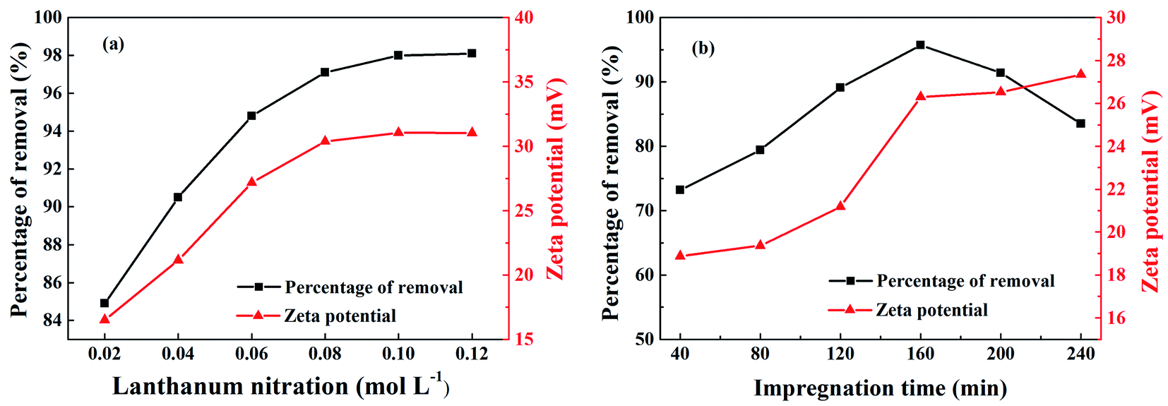 | ||
| Fig. 1 Effect of different conditions on phosphorus removal rate and zeta potential of La@ZIF-8: (a) lanthanum nitrate concentration, and (b) immersion time. | ||
The effect of impregnation time on phosphorus removal rate and zeta potential are shown in Fig. 1(b). When the impregnation time was less than 160 minutes, the phosphorus removal rate and zeta potential increased with time. At the impregnation time of 160 minutes, the phosphorus removal rate reached 95.7% and the zeta potential reached 26.29 mV. At this time, the system was relatively stable and the dispersion effect was optimum. However, the phosphorus removal rate showed a downward trend after the impregnation time exceeded 160 minutes. With the increase of impregnation time, the active sites on the surface of the MOF could be gradually occupied and saturated by La(OH)3. However, when the impregnation time became too long, local agglomeration of La(OH)3 could occur decreasing the numbers of active sites, which reduced the phosphorus removal rate of La@ZIF-8.
Based on the abovementioned results, the optimum experimental conditions for the preparation of La@ZIF-8 composites were determined as follows: a concentration of lanthanum nitrate of 0.08 mol L−1, and an impregnation time of 160 minutes. Under the optimized conditions, La@ZIF-8 delivered both high phosphorus adsorption performance and good system stability.
3.2 Morphologies and microstructures of La@ZIF-8
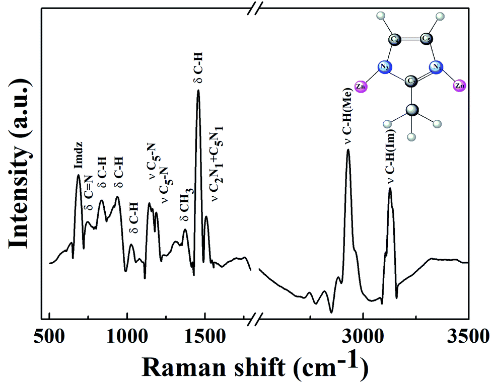 | ||
| Fig. 2 Raman spectrum of ZIF-8. The inset shows the methyl imidazole group of ZIF-8. | ||
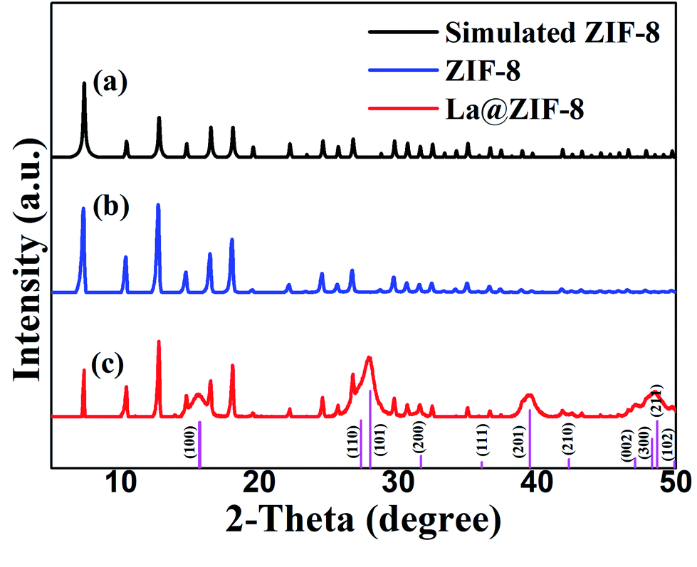 | ||
| Fig. 3 XRD patterns of the simulated ZIF-8, and the as-prepared ZIF-8 and La@ZIF-8 samples. | ||
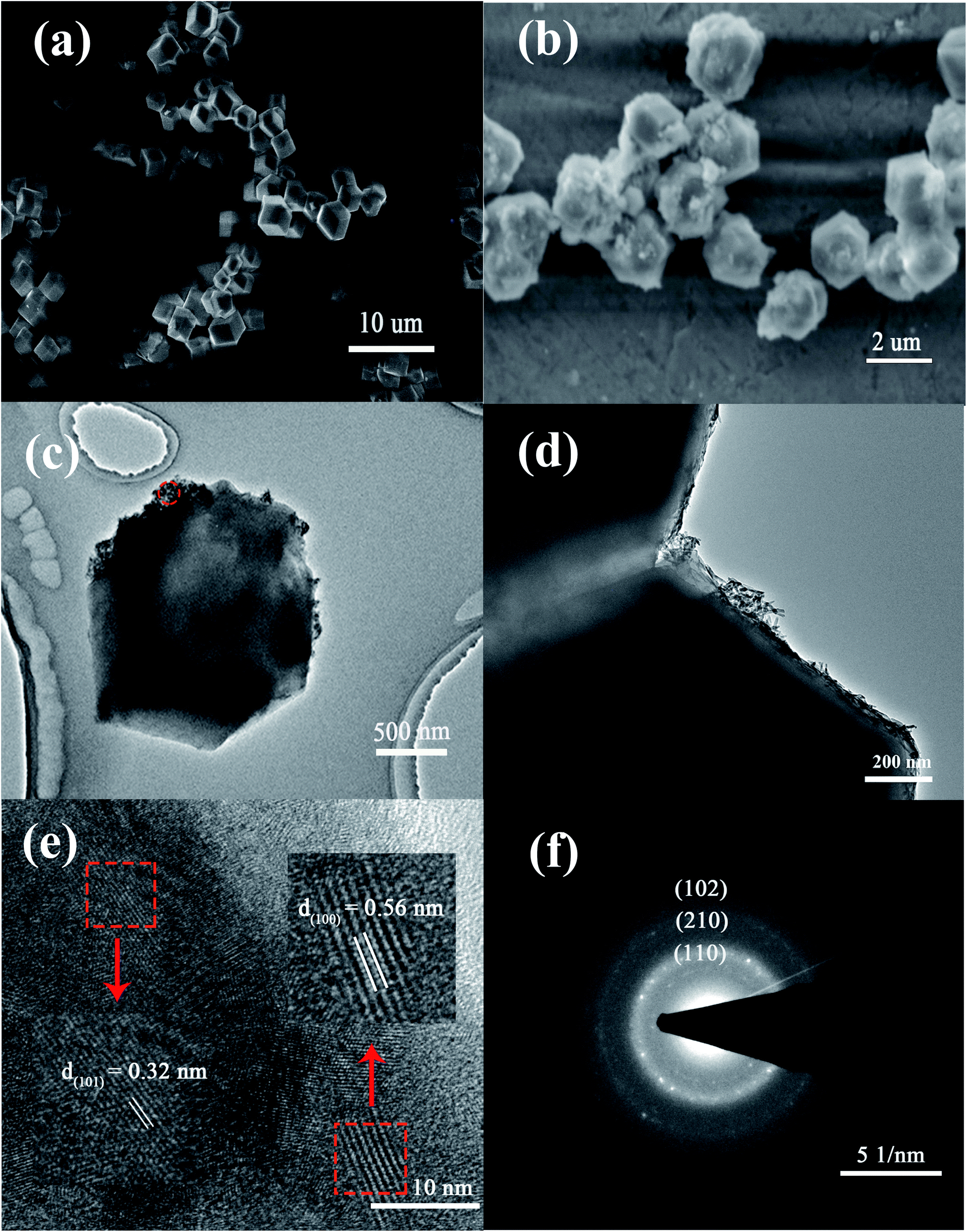 | ||
| Fig. 4 (a and b) SEM images of ZIF-8 and La@ZIF-8; (c and d) TEM image of La@ZIF-8 at different magnifications; (e) HRTEM images of La(OH)3 (the inner chart shows the average lattice spacing); (f) SAED pattern of La@ZIF-8. | ||
TEM images of the La@ZIF-8 at different magnifications are presented in Fig. 4(c) and (d). As can be seen from Fig. 4(c), the adhesion of the active component lanthanum hydroxide is not uniform, and its attachment location is relatively random. Moreover, it basically adheres to the surface of the material, indicating that attachment sites of active component exist on the surface of ZIF-8. In addition, it can be seen from Fig. 4(d) that the rod-like lanthanum hydroxide is stacked in a disorderly manner on the surface of the material and forms a porous channel structure; the adsorption performance could be improved because of this.
More evidence for crystals on the surface of La@ZIF-8 is provided through a high-resolution TEM (HR-TEM, Fig. 4(e)). The HR-TEM images correspond to the area identified by the red circle in (c). The HR-TEM results show clear lattice fringes with d-spacings of 0.32 nm and 0.56 nm belonging to the lattice fringe of the (101) and (100) planes for La(OH)3. Furthermore, the selected-area electron diffraction (SAED) pattern (Fig. 4(f)) shows clear polycrystalline diffraction rings, corresponding to the (102), (110), and (210) planes of La(OH)3.
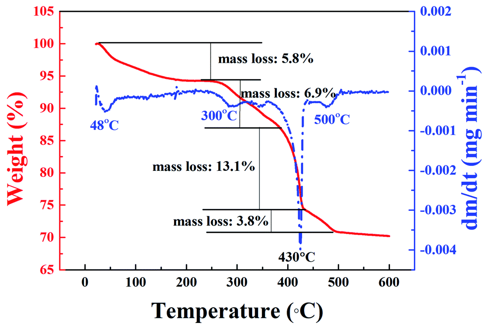 | ||
| Fig. 5 TGA and DTG curves of La@ZIF-8. | ||
![[double bond, length as m-dash]](https://www.rsc.org/images/entities/char_e001.gif) N. A strong and broad –OH characteristic peak appears at 3412 cm−1 in Fig. 6(b) due to the large amount of lanthanum hydroxide on the surface of ZIF-8. A sharp bending vibration absorption band of La–O is also obvious at 640 cm−1, indicating that La@ZIF-8 is well loaded with lanthanum hydroxide. The FT-IR spectrum (c) of the recycled material P–La@ZIF-8 shows significant characteristic absorption peaks of La–P at 1052 cm−1, indicating that La@ZIF-8 could strongly adsorb phosphate ions.
N. A strong and broad –OH characteristic peak appears at 3412 cm−1 in Fig. 6(b) due to the large amount of lanthanum hydroxide on the surface of ZIF-8. A sharp bending vibration absorption band of La–O is also obvious at 640 cm−1, indicating that La@ZIF-8 is well loaded with lanthanum hydroxide. The FT-IR spectrum (c) of the recycled material P–La@ZIF-8 shows significant characteristic absorption peaks of La–P at 1052 cm−1, indicating that La@ZIF-8 could strongly adsorb phosphate ions.
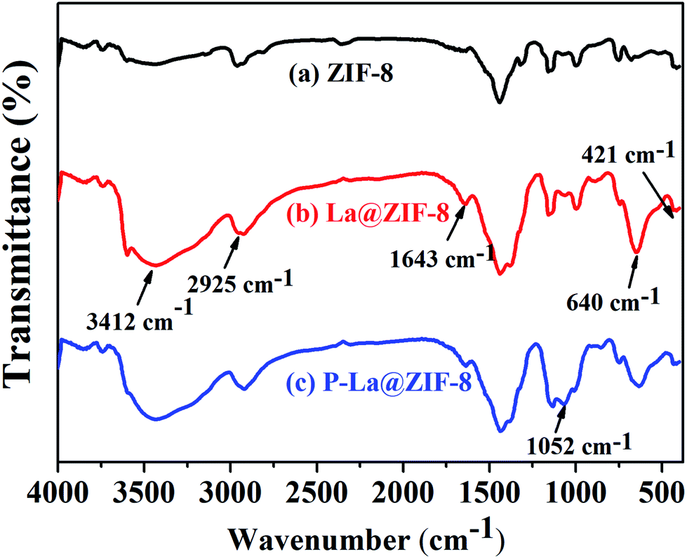 | ||
| Fig. 6 FT-IR spectra of ZIF-8, La@ZIF-8 and P–La@ZIF-8. | ||
3.3 Effect of different conditions on the adsorption of phosphate
Fig. 7(a) shows a comparison of the phosphorus removal capacity of ZIF-8 and La@ZIF-8. It can be seen that when the initial phosphorus concentration is 70 mg L−1, the adsorption capacities of the two are 61.37 mg g−1 and 147.63 mg g−1, respectively, which indicates that the loading of La(OH)3 in the composites can effectively improve the adsorption capacity and plays an important role in phosphorus removal.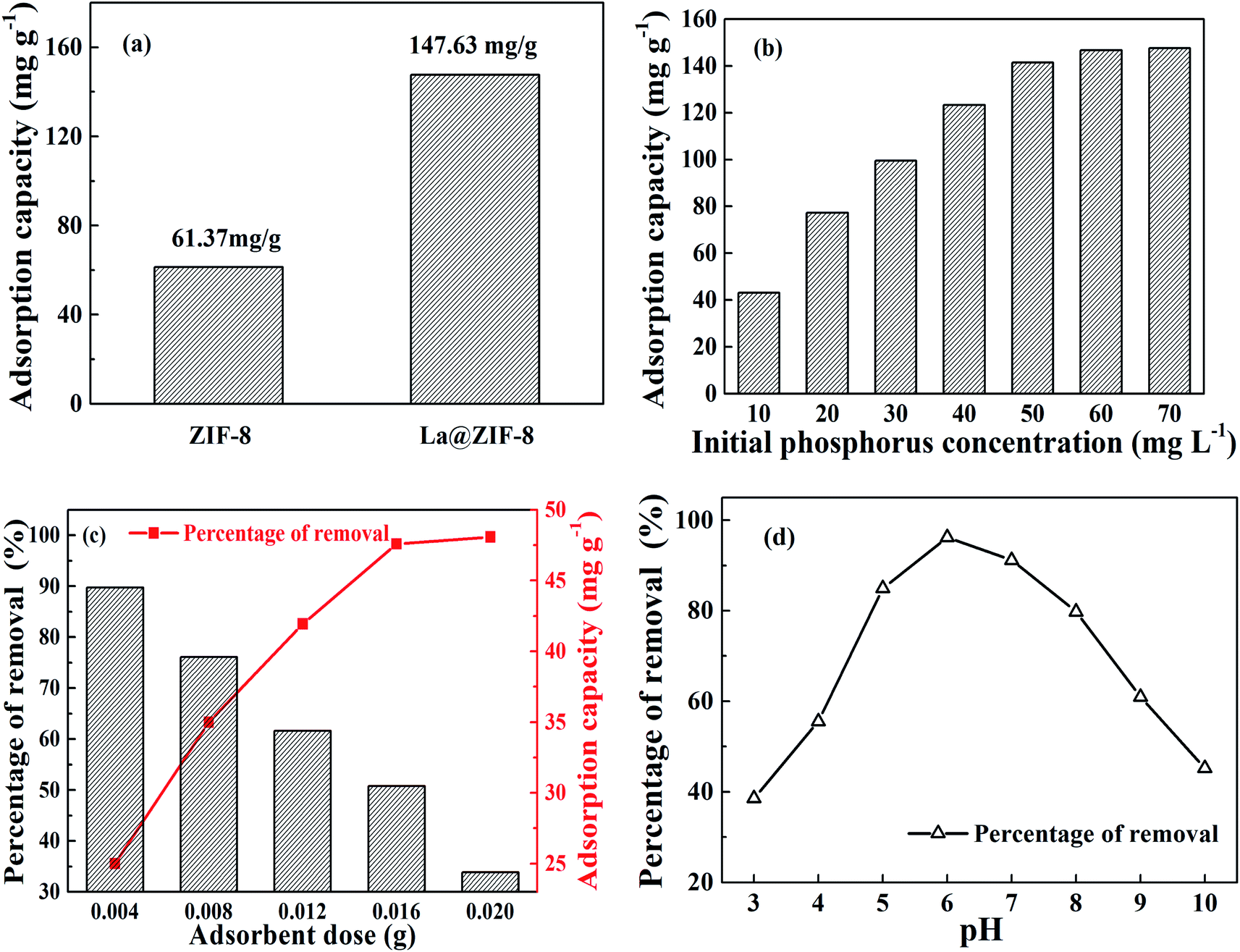 | ||
| Fig. 7 Effect of different conditions on the adsorption of phosphate: (a) phosphorus removal capacity of ZIF-8 and La@ZIF-8, (b) initial phosphorus concentration, (c) adsorbent dosage, and (d) initial solution pH. | ||
The effect of initial phosphorus concentration on adsorption capacity is recorded in Fig. 7(b). When the initial phosphorus concentration was low, the adsorption capacity increased rapidly as the phosphorus concentration increased. Unfortunately, when the mass concentration of phosphorus reached 70 mg L−1, the adsorption capacity reached a plateau at 147.63 mg g−1, after which it remained almost unchanged. This is because the adsorption sites on La@ZIF-8 composites had been gradually occupied with the increasing levels of phosphorus. However, the number of adsorption sites was limited when the dosage of La@ZIF-8 was fixed. Therefore, with increasing phosphorus content, the adsorption capacity gradually increased and then reached saturation.
The effects of La@ZIF-8 dosage on the phosphorus removal rate and adsorption capacity are shown in Fig. 7(c). Evidently, the removal efficiency of phosphate increased with the adsorbent amount from 0.004 g L−1 to 0.020 g L−1, while the adsorption capacity declined continuously. After that, as more adsorbent was added to the solution, the removal efficiency remained at equilibrium because the number of active adsorption sites were limited at lower amounts of La@ZIF-8, leading to a lower phosphate removal efficiency. However, when the amount of adsorbent increased above 0.020 g L−1, the active adsorption sites were abundant, and the removal efficiency reached 99.7%. The adsorption capacity at the adsorbent dosage of 0.020 g L−1 was lower than that at 0.016 g L−1 because of the excess of adsorbent. Consequently, based on economical and practical considerations, the adsorbent dosage of 0.016 g L−1 was selected as the optimum dosage.
Fig. 7(d) shows the effect of different pH values on phosphorus removal rate. Phosphoric acid is mainly present in the form of H3PO4, H2PO4−, HPO42−, and PO43− in solution.20 Specially, the pH value affects the forms of phosphoric acid in water. At pH = 3, phosphoric acid exists mainly in the form of H3PO4, and the affinity between H3PO4 and La@ZIF-8 is low, which explains why the phosphorus removal rate was low. With the increase of hydrogen ion concentration, more H2PO4− is found in solution, which has a high affinity for La@ZIF-8, and the phosphorus removal rate increased accordingly. Then at pH = 6, both the adsorption capacity and the phosphorus removal rate reached their highest. However, when the pH value increased further, the phosphorus removal rate decreased because HPO42− is the main form of phosphate in solution at pH > 7, and the affinity of hydrazine for HPO42− is lower than that for H2PO4−. At the same time, when the pH was high, the OH− in the solution interfered with the adsorption of phosphate, which led to a decrease in adsorption capacity and phosphorus removal rate.
3.4 Adsorption kinetics
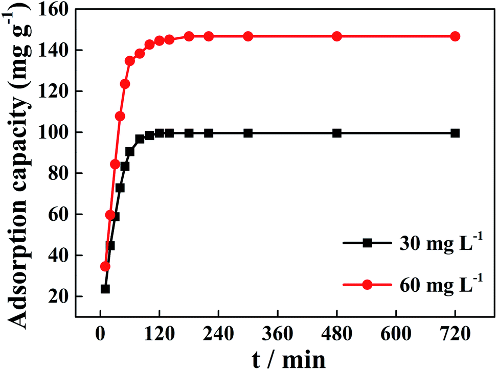 | ||
| Fig. 8 Adsorption kinetics for phosphate on La@ZIF-8 at different initial phosphate concentrations. | ||
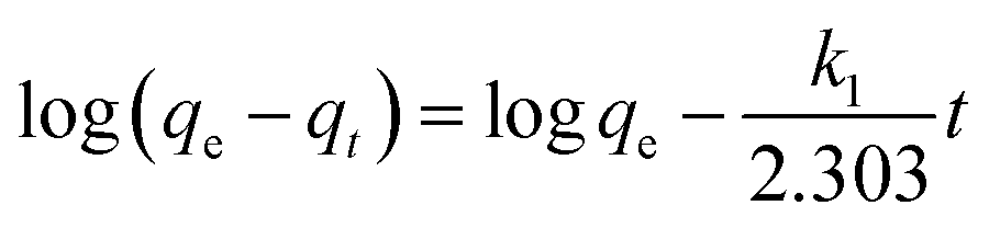
The pseudo-first-order kinetic model is expressed as:40,41
 | (3) |
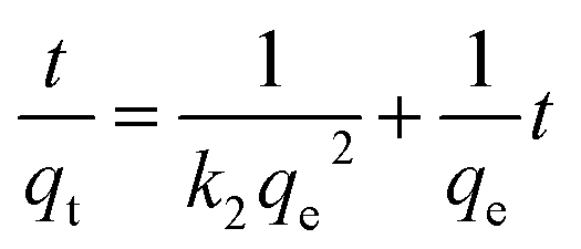
The pseudo-second-order kinetic model is expressed as:40,41
 | (4) |
The experimental data for the phosphorus adsorption capacity of La@ZIF-8 were analyzed using the pseudo-first-order and pseudo-second-order kinetic models. Fig. 9 shows the linear relationships of the two adsorption kinetic models obtained by fitting the experimental data. Table 1 exhibits some correlative parameters of the kinetic models. Compared with the pseudo-first-order kinetic model, the correlation coefficients R2 of the quasi-second-order kinetic model were higher at above 0.99 for both phosphorus concentration levels. The high R2 values for the pseudo-second-order kinetic equation imply the feasibility of phosphate adsorption on La@ZIF-8. In addition, the theoretical maximum adsorption levels of 102.0 mg g−1 (30 mg L−1 phosphorus solution) and 151.5 mg g−1 (60 mg L−1 phosphorus solution), were only slightly different from the experimental values of 99.51 mg g−1 and 146.70 mg g−1, respectively, further verifying the applicability of the pseudo-second-order kinetic model.18 Accordingly, these results suggest that the phosphate adsorption process is chemical in nature, achieved by sharing electrons between phosphate ions and adsorbent.
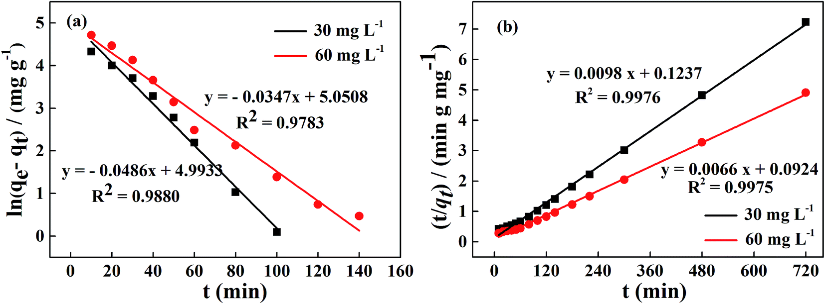 | ||
| Fig. 9 Adsorption kinetics for phosphate on La@ZIF-8 at two different initial phosphate concentrations: (a) pseudo-first-order kinetic equation fitting curve, (b) pseudo-second-order kinetic equation fitting curve. | ||
| co/(mg L−1) | qe,exp/(mg g−1) | Pseudo-first-order kinetic model | Pseudo-second-order kinetic model | ||||
|---|---|---|---|---|---|---|---|
| qe/(mg g−1) | k1/(min) | R2 | qe/(mg g−1) | k2/[g (mg min)−1] | R2 | ||
| 30 | 99.51 | 147.42 | 0.0486 | 0.9880 | 102.04 | 7.764 × 10⁻⁴ | 0.9976 |
| 60 | 146.70 | 156.16 | 0.0347 | 0.9783 | 151.52 | 4.714 × 10⁻⁴ | 0.9975 |
3.5 Adsorption isotherm curve
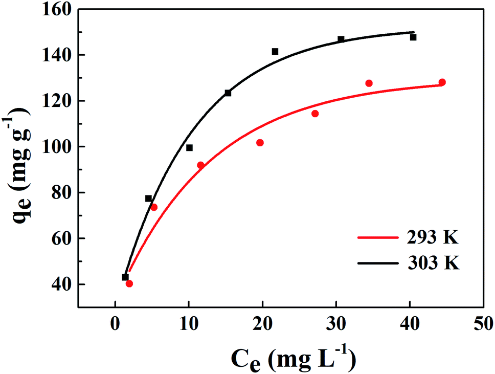 | ||
| Fig. 10 Adsorption isotherms of phosphate on La@ZIF-8 at different temperatures. | ||
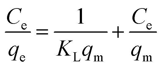
The Langmuir model describes the adsorption equilibrium of a single layer on a homogeneous surface at constant temperature.
The Langmuir isothermal model is expressed as: 20,40,42
 | (5) |
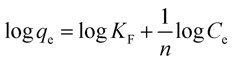
However, solid surfaces are often heterogeneous, with different adsorption energies at different locations, and the heat of adsorption can vary with surface coverage. Therefore, the following Freundlich empirical formula was proposed.
The Freundlich isothermal model is expressed as:20,40,42
 | (6) |
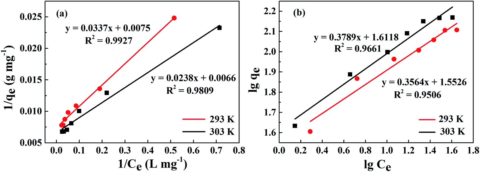
The linear fitting of the Langmuir model is shown in Fig. 11(a). Table 2 exhibits some correlative parameters of the isotherm models. Compared with the Freundlich model as displayed in Fig. 11(b), the correlation coefficients of the Langmuir model were greater at more than 0.9800, which indicates that the Langmuir model could better describe the phosphorus adsorption process of La@ZIF-8. Furthermore, in this model, the adsorption capacity of La@ZIF-8 reached 151.51 mg g−1 at 303 K, which is close to the experimental determination of 147.63 mg g−1. This indicates that the Langmuir model can be used to describe the adsorption behavior of La@ZIF-8 for phosphate. Accordingly, the results reveal that phosphate adsorbs as a homogeneous monolayer on La@ZIF-8.
 | ||
| Fig. 11 Adsorption isotherms of phosphate on La@ZIF-8 at different temperatures: (a) Langmuir equation fitting curve, (b) Freundlich equation fitting curve. | ||
| Temperature/(K) | qe,exp/(mg g−1) | Langmuir model | Freundlich model | ||||
|---|---|---|---|---|---|---|---|
| qm/(mg g−1) | KL/(L mg−1) | R2 | n/(L mg−1) | KF/(mg g−1) | R2 | ||
| 293 | 137.20 | 133.33 | 0.22 | 0.9927 | 2.81 | 35.69 | 0.9506 |
| 303 | 147.63 | 151.51 | 0.28 | 0.9809 | 2.64 | 41.50 | 0.9661 |
3.6 The regeneration of adsorbent
In actual application, the re-usability of adsorbents is an important characteristic. Therefore, five experiments of adsorption–desorption recycling using simulated wastewater containing 5 mg L−1 phosphorus were carried out. NaOH standard solution (1.0 mol L−1) was used as the eluent and stirred with the composite at room temperature for 12 hours.Five cycles of adsorption–desorption of phosphate by La@ZIF-8 are shown in Fig. 12. Over the five cycles, the phosphorus removal efficiency decreased slightly with the number of recycling times, which might be caused by the loss of materials in the recycling process. However, the desorption efficiency was maintained at more than 90%, indicating that La@ZIF-8 composites have good re-usability.
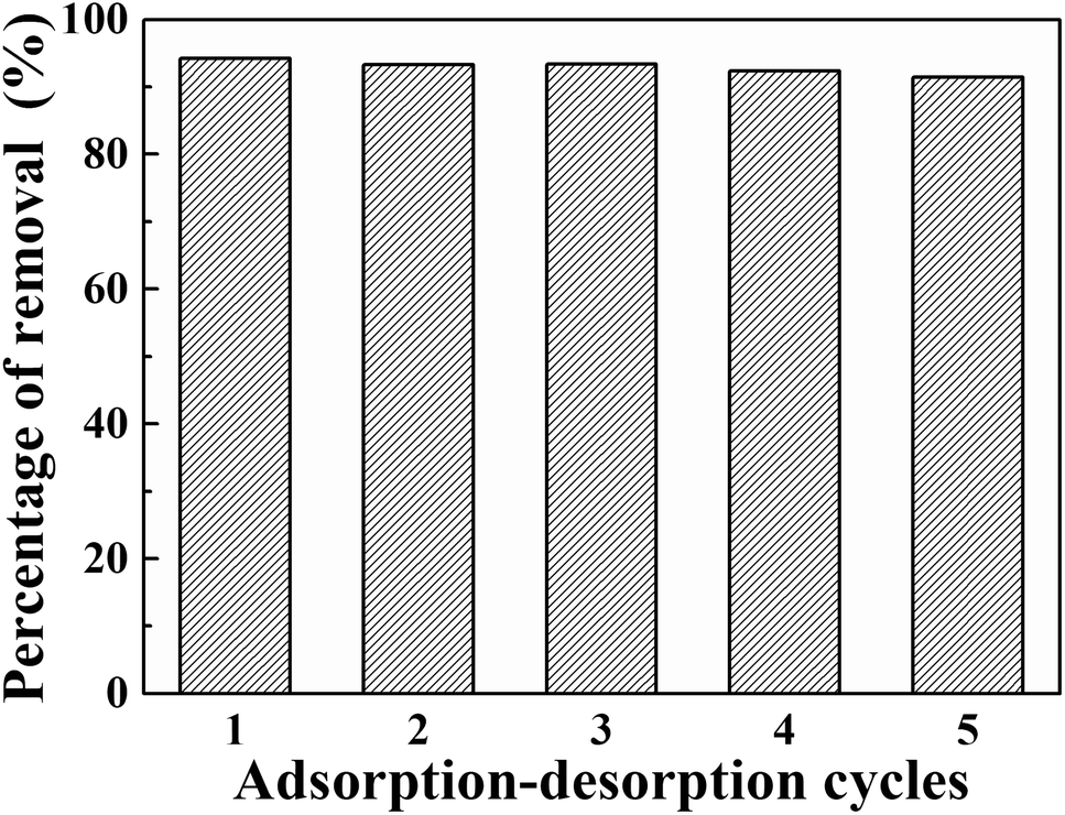 | ||
| Fig. 12 Reusability of La@ZIF-8 for the adsorptive removal of phosphate. | ||
3.7 Adsorption mechanisms
Phosphoric acid is mainly present in solution in the forms of H3PO4, H2PO4−, HPO42−, and PO43− depending on the pH value of the solution. Under strongly acidic conditions, the main form of phosphate in solution is H3PO4. The binding ability of H3PO4 to La@ZIF-8 composite is weak. Under weakly acid conditions, H2PO4− is the major species in solution. On the one hand, due to the electrostatic attraction between La3+ and H2PO4−, La3+ in the composite can easily form a complex with H2PO4−, which improves the phosphate adsorption capacity of the composite. On the other hand, La3+ binds a large amount of OH−. The OH− in the ZIF-8 can undergo ligand exchange with the phosphate ions in the solution, and the phosphate ions are therefore adsorbed on the surface, further enhancing the adsorption performance of the La@ZIF-8. However, with the increase of pH, the increased concentration of OH− makes the composite surface negatively charged, and the adsorption of phosphate is disadvantageous due to the electrostatic repulsion between the surface of the La@ZIF-8 and the phosphate ions. In addition, the ligand exchange further increases the pH value of the solution, which adversely affects the adsorption of phosphate.4. Conclusions
In this study, the prepared La@ZIF-8 composites were used as adsorbents for the removal of phosphate. Through the study of phosphorus removal rate and zeta potential of La@ZIF-8 composites, the optimum synthesis conditions for La@ZIF-8 were obtained. Moreover, several primary experimental parameters (such as adsorbent dosage, pH, and regeneration ability, etc.) were investigated in detail. The results showed that La@ZIF-8 has high adsorption efficiency for phosphate pollutants and exhibits the most efficient phosphate removal performance at pH = 6.0. In addition, the adsorption kinetics of the La@ZIF-8 composite for phosphorus in solution accorded with the pseudo-second-order kinetic model. Compared with the Freundlich model, the Langmuir model more accurately described the adsorption behavior of La@ZIF-8 for phosphate. By considering the adsorption mechanism, it was found that not only electrostatic attractions, but also ligand exchange reactions between phosphate ions and La@ZIF-8 facilitate adsorption. Finally, NaOH solution was selected as the elution agent for the regeneration of the sorbents. After five adsorption–desorption cycles, the capacities for the regenerated sorbents were still higher than 90%. Naturally, these advantages make it possible for La@ZIF-8 to become one of the most effective and promising adsorbent materials for phosphate in actual applications.Conflicts of interest
We declare that we do not have any commercial or associative interest that represents a conflict of interest in connection with the work submitted.Acknowledgements
This work was financially supported by the National Natural Science Foundation of China (Grant No. 21276156).References
- W. Guo, Y. Fu, B. Ruan, H. Ge and N. Zhao, Ecol. Indic., 2014, 36, 254–261 CrossRef CAS.
- W. Zhang, X. Jin, D. Liu, C. Lang and B. Shan, J. Environ. Sci., 2017, 5, 41–48 CrossRef PubMed.
- S. C. Schneider, M. Cara, T. E. Eriksen, B. Budzakoska Goreska, A. Imeri, L. Kupe, T. Lokoska, S. Patceva, S. Trajanovska and S. Trajanovski, Limnologica, 2014, 44, 90–97 CrossRef CAS.
- Z. K. Ni, S. R. Wang and Y. M. Wang, Environ. Pollut., 2016, 219, 537–544 CrossRef CAS PubMed.
- L. W. Ngatia, Y. P. Hsieh, D. Nemours, R. Fu and R. W. Taylor, Chemosphere, 2017, 180, 201–211 CrossRef CAS PubMed.
- L. A. Wendling, P. Blomberg, T. Sarlin, O. Priha and M. Arnold, Appl. Geochem., 2013, 37, 157–169 CrossRef CAS.
- H. C. Guo and T. Ouyang, J. Xiamen Univ., Nat. Sci., 2006, 45, 540–544 CAS.
- Y. Yao, B. Gao, M. Inyang, A. R. Zimmerman, X. D. Cao, P. Pullammanappallil and L. Y. Yang, J. Hazard. Mater., 2011, 190, 501–507 CrossRef CAS PubMed.
- J. W. Lin, Y. Liu and Y. H. Yan, J. Environ. Eng., 2010, 4, 575–580 CAS.
- Q. P. Cheng, H. X. Li, Y. L. Xu, S. Chen, Y. H. Liao, F. Deng and J. F. Li, PLoS One, 2017, 12, 1–12 Search PubMed.
- B. Kostura, H. Kulveitová and J. Lesko, Water Res., 2005, 39, 1795–1802 CrossRef CAS PubMed.
- J. H. Xu, Y. M. Li and Y. F. Xie, Non-Metallic Mines, 2006, 5, 44–46 Search PubMed.
- Y. P. Yan, F. Liu, W. Li, F. Liu, X. H. Feng and D. L. Sparks, Eur. J. Soil Sci., 2014, 65, 308–317 CrossRef CAS.
- C. Jiang, L. Y. Jia, Y. L. He, B. Zhang, G. Kirumba and J. Xie, J. Colloid Interface Sci., 2013, 402, 246–252 CrossRef CAS PubMed.
- Z. L. Shi, F. M. Liu and S. H. Yao, N. Carbon Mater., 2011, 26, 299–306 CrossRef CAS.
- K. S. Park, Z. Ni, A. P. Côté, J. Y. Choi, R. Huang, F. J. Uriberomo, H. K. Chae, M. O'Keeffe and O. M. Yaghi, Proc. Natl. Acad. Sci. U. S. A., 2006, 103, 10186–10191 CrossRef CAS PubMed.
- V. M. Aceituno Melgar, H. Ahn, J. Kim and M. R. Othman, J. Ind. Eng. Chem., 2015, 21, 575–579 CrossRef CAS.
- Y. Y. Liu, Z. Ng, E. A. Khan, H. K. Jeong, C. Ching and Z. P. Lai, Microporous Mesoporous Mater., 2009, 118, 296–301 CrossRef CAS.
- C. S. Wu, Z. H. Xiong, C. Li and J. M. Zhang, RSC Adv., 2015, 5, 82127–82137 RSC.
- H. Liu, W. Guo, Z. Liu, X. Li and R. Wang, RSC Adv., 2016, 6, 105282–105287 RSC.
- X. K. Qian, F. X. Sun, J. Sun, H. Wu, F. Xiao, X. Y. Wu and G. S. Zhu, Nanoscale, 2017, 9, 2003–2008 RSC.
- N. T. T. Nguyen, H. Furukawa, F. Gándara, H. T. Nguyen, K. E. Cordova and O. M. Yaghi, Angew. Chem., Int. Ed., 2015, 53, 10645–10648 CrossRef PubMed.
- H. Hayashi, A. P. Caté, H. Furukawa, M. O'Keeffe and O. M. Yaghi, Nat. Mater., 2007, 6, 501–506 CrossRef CAS PubMed.
- X. K. Qian, Q. B. Ren, X. F. Wu, J. Sun, H. Y. Wu and J. Lei, ChemistrySelect, 2018, 3, 657–661 CrossRef CAS.
- H. L. Jiang, B. Liu, T. Akita, M. Haruta, H. Sakurai and Q. Xu, J. Am. Chem. Soc., 2009, 131, 11302–11303 CrossRef CAS PubMed.
- D. Peralta, G. Chaplais, A. Simon-Masseron, K. Barthelet and G. D. Pirngruber, Ind. Eng. Chem. Res., 2012, 51, 4692–4702 CrossRef CAS.
- L. Zhang, G. Qian, Z. J. Liu, Q. Cui, H. Y. Wang and H. Q. Yao, Sep. Purif. Technol., 2015, 156, 472–479 CrossRef CAS.
- Y. H. Wang, S. G. Jin, Q. Y. Wang, G. H. Lu, J. J. Jiang and D. R. Zhu, J. Chromatogr. A, 2013, 1291, 27–32 CrossRef CAS PubMed.
- Y. W. Cui, J. Li and Z. F. Du, J. Rare Earths, 2016, 34, 460–467 Search PubMed.
- S. R. Venna, J. B. Jasinski and M. A. Carreon, J. Am. Chem. Soc., 2010, 132, 18030–18033 CrossRef CAS PubMed.
- N. K. Demir, B. Topuz, L. Yilmaz and H. Kalipcilar, Microporous Mesoporous Mater., 2014, 198, 291–300 CrossRef.
- D. A. Carter and J. E. Pemberton, J. Raman Spectrosc., 2015, 28, 939–946 CrossRef.
- C. J. Mao, X. W. Hu, J. M. Song, H. L. Niu and S. Y. Zhang, Crystengcomm, 2012, 14, 6823–6826 RSC.
- T. T. Xing, Y. B. Lou, Q. L. Bao and J. X. Chen, Crystengcomm, 2014, 16, 8994–9000 RSC.
- H. Bux, A. Feldhoff, J. Cravillon, M. Wiebcke, Y. S. Li and J. Caro, Chem. Mater., 2011, 23, 2262–2269 CrossRef CAS.
- S. R. Venna and M. A. Carreon, J. Am. Chem. Soc., 2010, 132, 76–78 CrossRef CAS PubMed.
- N. T. Tran, J. Kim and M. R. Othman, Microporous Mesoporous Mater., 2019, 285, 178–184 CrossRef CAS.
- E. Shamsaei, Z. X. Low, X. Lin, A. Mayahi, H. Liu, X. Zhang, J. Z. Liu and H. Wang, Chem. Commun., 2015, 51, 11474–11477 RSC.
- Y. Hu, H. Kazemian, S. Rohani, Y. N. Huang and Y. Song, Chem. Commun., 2011, 47, 12694–12696 RSC.
- J. Lalley, C. Han, X. Li, D. D. Dionysiou and M. N. Nadagouda, Chem. Eng. J., 2016, 284, 1386–1396 CrossRef CAS.
- A. Sari and M. Tuzen, J. Hazard. Mater., 2008, 157, 448–454 CrossRef CAS PubMed.
- A. Sari and M. Tuzen, J. Hazard. Mater., 2009, 171, 973–979 CrossRef CAS PubMed.
| This journal is © The Royal Society of Chemistry 2020 |