 Open Access Article
Investigation of calcium carbonate synthesized by steamed ammonia liquid waste without use of additives
Xianping Luo *abcd,
Xuewen Song
 *a,
Yuwei Caoc,
Lei Songc and
Xianzhong Bub
aCollege of Material Science and Engineering, Xian University of Architecture and Technology, Xian, 710055, China. E-mail: luoxianping9491@163.com; Fax: +86 0797 8312227; Tel: +86 0797 8312553
bSchool of Resources Engineering, Xian University of Architecture and Technology, Xian, 710055, China
cWestern Mining Group Co., Ltd., Xining, 810001, China
dSchool of Resources and Environmental Engineering, Jiangxi University of Science and Technology, Ganzhou, 341000, China
First published on 2nd March 2020
Abstract
The aim of this work is to study the effect of reaction conditions using steamed ammonia liquid waste without the use of additives on the crystallization of calcium carbonate. CaCO3 was prepared by steamed ammonia liquid waste (CaCl2) and (NH4)2CO3 solution. The produced crystals were characterized by scanning electron microscopy (SEM), Fourier transform infrared spectrometry (FTIR) and X-ray diffraction (XRD). We have investigated the effect of the concentration of reactants, stirring speed, Ca2+![[thin space (1/6-em)]](https://www.rsc.org/images/entities/char_2009.gif) :
:![[thin space (1/6-em)]](https://www.rsc.org/images/entities/char_2009.gif) CO32− ratio, aging time and adding mode on the particle size and size distribution, final morphology and polymorph of calcium carbonate crystals during precipitation. The influence of concentration of reactants, stirring speed, Ca2+
CO32− ratio, aging time and adding mode on the particle size and size distribution, final morphology and polymorph of calcium carbonate crystals during precipitation. The influence of concentration of reactants, stirring speed, Ca2+![[thin space (1/6-em)]](https://www.rsc.org/images/entities/char_2009.gif) :
:![[thin space (1/6-em)]](https://www.rsc.org/images/entities/char_2009.gif) CO32− ratio, aging time and adding mode on the morphology, size and polymorph of CaCO3 particles and possible formation mechanism were discussed. The exploration provides the possibility for large-scale synthesis of CaCO3 materials with controllable morphology and crystallographic structure by steamed ammonia liquid waste without use of additives at room temperature.
CO32− ratio, aging time and adding mode on the morphology, size and polymorph of CaCO3 particles and possible formation mechanism were discussed. The exploration provides the possibility for large-scale synthesis of CaCO3 materials with controllable morphology and crystallographic structure by steamed ammonia liquid waste without use of additives at room temperature.
1. Introduction
Western Mining Group Co., Ltd. uses salt lake bischofite and NH3 as raw materials to prepare magnesium hydroxide. The formation process of magnesium hydroxide uses the following three steps, which are based on the reaction below: (1–3).At present, the annual production of magnesium hydroxide by Western Mining Group Co., Ltd. has reached 100![[thin space (1/6-em)]](https://www.rsc.org/images/entities/char_2009.gif) 000 tons, and the annual output of steamed ammonia waste liquid is nearly 200
000 tons, and the annual output of steamed ammonia waste liquid is nearly 200![[thin space (1/6-em)]](https://www.rsc.org/images/entities/char_2009.gif) 000 tons. The large amount of discharged steamed ammonia waste liquid causes serious resource waste and environmental pollution, which restricts the further development of the enterprise. It is of great value to realize the recovery and utilization of steamed ammonia liquid waste. Steamed ammonia liquid waste reacts with ammonium carbonation products CaCO3, and is a useful way of treating steamed ammonia liquid waste.
000 tons. The large amount of discharged steamed ammonia waste liquid causes serious resource waste and environmental pollution, which restricts the further development of the enterprise. It is of great value to realize the recovery and utilization of steamed ammonia liquid waste. Steamed ammonia liquid waste reacts with ammonium carbonation products CaCO3, and is a useful way of treating steamed ammonia liquid waste.
Calcium carbonate (CaCO3) is one of the most studied inorganic chemical materials, which has the advantages of cheap availability, good heat resistance, nontoxicity and good biocompatibility with the human body, so it is widely used as a filling and reinforcing agent for coating, paper, printing ink, textile, rubber and plastics,1–4 as well as nutritive agent for toothpaste, food, medicine and feed.5 The preparation of CaCO3 from steamed ammonia liquid waste has great economic and environmental effects. However, the reaction of steamed ammonia liquid waste with (NH4)2CO3 is complex, and the product CaCO3 is quite sensitive to process parameters. At the same time application field of CaCO3 particles with different properties and functions are different, the morphology of CaCO3, dispersion and particle size on its physical and chemical properties have large influence. CaCO3 properties largely depends on its morphology characteristics, particle size and dispersion, such as the preparation of a special morphology, crystal structure, controllable size and good dispersion. CaCO3 material is an important index in the inorganic chemical materials field. To control the crystallization process of CaCO3, reduce the production cost, improve the product performance and broaden the application range of the product is the focus of the field of CaCO3 preparation.
CaCO3 has calcite (rhombohedral), aragonite (orthorhombic) and vaterite (hexagonal) three anhydrous polymorphs.6 It has been well established that the different polymorphs of CaCO3 synthesized in an aqueous solution possess different morphologies: rhombohedral phased calcite is usually found as cubic particles, orthorhombic aragonite usually found as needle-like particles, while vaterite has a hexagonal structure that normally leads to spherical particles,7 the CaCO3 morphology, size, crystal structure, density, color, brightness and other physicochemical properties of a material are strongly dependent on its preparation technology. Several techniques have been used to manufacture special morphologies, different polymorphs, controllable size, well dispersed CaCO3, such as carbonation,8–12 solvo or hydrothermal synthesis12,13, microwave-assisted synthesis,14–17 sonochemical synthesis,18 double water-in-oil-in-water emulsion,19 wet precipitation20,21 and other special synthesis processes and methods.22
Now, precipitation method is the most important method to prepare CaCO3, the relationship between precipitation conditions and morphology of CaCO3 is the object of many experimental studies but it still is disputed,23 it has been reported that synthetic factors including concentration of reactants, stirring speed, Ca2+![[thin space (1/6-em)]](https://www.rsc.org/images/entities/char_2009.gif) :
:![[thin space (1/6-em)]](https://www.rsc.org/images/entities/char_2009.gif) CO32− ratio, aging time and adding mode may significantly affect the formation of the polymorphs CaCO3. By adjusting the preparation conditions of CaCO3, the crystal phase, morphology and particle size of CaCO3 can be controlled. For example, Yongsheng Wang24 et al. compared the influence CaCO3 in the poly(sodium 4-styrene sulfonate) presence and absence, the investigated show that when the poly(sodium 4-styrene sulfonate) presence the crystal shape and particle size of prepared CaCO3 can be changed by changing the concentration of Ca2+ and CO32− ions in the initial solution. The Yong Sheng Han and coworkers23 study result of showed that the initial CaCl2 concentration it can affect the pH of the reaction system and thus ultimately determine the prepared calcium carbonate crystal type. Yohta Mori25 research indicated that the stirring method can effected the particle size of CaCO3 crystal. Santos Rafael M26 and coworkers by reducing the CO2 flow rate and forming a higher Ca2+
CO32− ratio, aging time and adding mode may significantly affect the formation of the polymorphs CaCO3. By adjusting the preparation conditions of CaCO3, the crystal phase, morphology and particle size of CaCO3 can be controlled. For example, Yongsheng Wang24 et al. compared the influence CaCO3 in the poly(sodium 4-styrene sulfonate) presence and absence, the investigated show that when the poly(sodium 4-styrene sulfonate) presence the crystal shape and particle size of prepared CaCO3 can be changed by changing the concentration of Ca2+ and CO32− ions in the initial solution. The Yong Sheng Han and coworkers23 study result of showed that the initial CaCl2 concentration it can affect the pH of the reaction system and thus ultimately determine the prepared calcium carbonate crystal type. Yohta Mori25 research indicated that the stirring method can effected the particle size of CaCO3 crystal. Santos Rafael M26 and coworkers by reducing the CO2 flow rate and forming a higher Ca2+![[thin space (1/6-em)]](https://www.rsc.org/images/entities/char_2009.gif) :
:![[thin space (1/6-em)]](https://www.rsc.org/images/entities/char_2009.gif) CO32− ratio finally found higher Ca2+
CO32− ratio finally found higher Ca2+![[thin space (1/6-em)]](https://www.rsc.org/images/entities/char_2009.gif) :
:![[thin space (1/6-em)]](https://www.rsc.org/images/entities/char_2009.gif) CO32− ratio is beneficial to the formation of aragonite CaCO3. Hongxia Guo27 et al. investigated the reaction concentration and reaction time both could effected the polymorphs of prepared CaCO3. Ashvin T. Nagaraja28 reported that CaCO3 particle size, dispersion and surface charge can be controlled by controlling PVSA concentration, reaction temperature and reagent addition sequence, and finally CaCO3 with an average particle size of 150–500 nm can be obtained under the best preparation conditions. The effects of reaction temperature (T = 30–90 °C) and stirring speed (200–600 rpm min−1) on the crystal structure of CaCO3 prepared without additives were studied by Radek Ševčík29 et al. Çağatay M. Oral30 synthesised different morphologies and polymorphs CaCO3 by changing the ratio of Ca2+ and CO32− of precursor solution under different pH conditions. Haichun Dang31 prepared hydrophobic spherical aragonite CaCO3 by high shear stirring.
CO32− ratio is beneficial to the formation of aragonite CaCO3. Hongxia Guo27 et al. investigated the reaction concentration and reaction time both could effected the polymorphs of prepared CaCO3. Ashvin T. Nagaraja28 reported that CaCO3 particle size, dispersion and surface charge can be controlled by controlling PVSA concentration, reaction temperature and reagent addition sequence, and finally CaCO3 with an average particle size of 150–500 nm can be obtained under the best preparation conditions. The effects of reaction temperature (T = 30–90 °C) and stirring speed (200–600 rpm min−1) on the crystal structure of CaCO3 prepared without additives were studied by Radek Ševčík29 et al. Çağatay M. Oral30 synthesised different morphologies and polymorphs CaCO3 by changing the ratio of Ca2+ and CO32− of precursor solution under different pH conditions. Haichun Dang31 prepared hydrophobic spherical aragonite CaCO3 by high shear stirring.
Although numerous previous studies have focused on the morphology, structure, particle size, specific surface area, polymorphs, chemical purity and so on of CaCO3 with of preparation condition. However, the determination of the relationship between precipitation conditions and product morphology is still a major challenge for research scientists. Therefore, developing an effective strategy to fabricate a crystalline material with controlled size, morphology, and crystal structure is of significance in chemical engineering. In this study, influence of concentration of reactants, stirring speed, Ca2+![[thin space (1/6-em)]](https://www.rsc.org/images/entities/char_2009.gif) :
:![[thin space (1/6-em)]](https://www.rsc.org/images/entities/char_2009.gif) CO32− ratio, aging time and adding mode on the morphology, size and polymorph of CaCO3 particles were investigated without referring to the use of any additives at initial pH and ambient temperature condition. In this paper explain the effect of preparation conditions on the physicochemical and structural properties such as the pore size distribution, specific surface area, brightness, adsorption capacity and chemical purity of CaCO3 prepared from steamed ammonia liquid waste, elucidate their exact features and to provide fundamental knowledge and insight into how to control the physicochemical and structural properties of CaCO3, and finally it provides theoretical support for the large-scale industrial production and application of to prepare CaCO3 by steamed ammonia liquid waste.
CO32− ratio, aging time and adding mode on the morphology, size and polymorph of CaCO3 particles were investigated without referring to the use of any additives at initial pH and ambient temperature condition. In this paper explain the effect of preparation conditions on the physicochemical and structural properties such as the pore size distribution, specific surface area, brightness, adsorption capacity and chemical purity of CaCO3 prepared from steamed ammonia liquid waste, elucidate their exact features and to provide fundamental knowledge and insight into how to control the physicochemical and structural properties of CaCO3, and finally it provides theoretical support for the large-scale industrial production and application of to prepare CaCO3 by steamed ammonia liquid waste.
2. Material and methods
2.1 Raw material
The raw materials steamed ammonia liquid waste were from Western Mining Group Co., Ltd. after three times of filtration to remove the solid impurities, the filtrated solution was used as the calcium source(CaCl2 solution) and the initial pH 11.17. Ammonium carbonate ((NH4)2CO3) was purchased from Tianjin Kemiou Chemical Reagent Company, China, and used without any further purification.2.2 Synthesis of calcium carbonate
The CaCO3 was synthesized via a precipitation. Steam ammonia waste liquid (CaCl2) and ammonium carbonate ((NH4)2CO3) was varying molar concentrations ranging from 0.15 to 0.60 mol L−1 by mixing with magnetic stirring. The steam ammonia waste liquid (CaCl2) and ammonium carbonate ((NH4)2CO3) were keep initial pH and no effort was made to adjust the pH of the solution. We selected room temperature because it does not need any temperature control which is not only inconvenient but also required specialized devices and thus incur additional cost and not feasible for industrial applications. Take a certain quantity of steam ammonia waste liquid and the (NH4)2CO3 solution was prepared by dissolving a certain amount of (NH4)2CO3 in deionized water. At the beginning of the reaction, the prepared steam ammonia waste liquid and the (NH4)2CO3 solution were immediately poured into a 500 mL conical bottle. After stirring a certain period of time, the product were collected by filtered, washed several times with deionized water and dried at 105 °C for 6 h.2.3 Characterization
For characterization of the precipitated CaCO3, a X-ray diffraction (XRD, DX-2700BH), a Fourier-transform infrared (FTIR, Cary 630) spectrometer and a scanning electron microscopy (SEM, phenom pro) was used. The resulting powders crystalline phases of was carried out using a Cu Kα source was used over a 2θ range of 20° to 60° and a step size of 0.02° with dwell time of 0.05 s was applied during the analyses. From intensity peaks of XRD patterns, the compositions of vaterite were estimated by eqn (4) as follows:32| fV = 7.691I110V/(7.691I110V+I104C) | (4) |
Fourier transmission infrared spectroscopy was performed on uniaxially pressed powder pellets mixed with KBr. The FTIR analyses were carried out in the 4000–400 cm−1 range with a resolution of 4 cm−1 and with 32 spectral scan repeats for each sample. The size and morphological structures of the precipitated CaCO3 were examined by scanning electron microscopy. Powder samples for SEM were uncoated and observed at a working distance of 3.5 mm and an accelerating voltage of 0.7 kV.
3. Results and discussion
3.1 Effect of initial CaCl2 and (NH4)2CO3 concentration on particle polymorph and morphology
A typical X-ray diffraction pattern of the CaCO3 particles prepared at various initial CaCl2 and (NH4)2CO3 concentration is shown in Fig. 1. The characteristic the strongest detected (hkl) peaks are at 2θ values of 23.1°, 29.4°, 36.0°, 39.4°, 43.2°, 47.5°, 48.5°correspond to the (012), (104), (110), (113), (202), (018), (116), (122), (214), (300) crystallographic planes of calcite, respectively. The X-ray diffraction pattern with peaks at 2θ values of values of 24.9°, 27.1°, 32.8°, 43.8°, 50.1°, 55.6°(Fig. 1b) correspond to the (100), (101), (102), (110), (104), (202) indicates that the composition of the CaCO3 microspheres are phase of vaterite. As shown in Fig. 1a, c and d with only calcite phase, however the main crystalline phase is vaterite and contains weak calcite (104) peak in samples b. We know from eqn (4), when the initial CaCl2 and (NH4)2CO3 concentration is 0.3 mol L−1 the content of the calcite and vaterite in the products are 7.51% and 92.49%, the content of the calcite and vaterite are 97.88%, 97.38%, 97.60% and 2.12%, 2.62%, 2.40% at 0.15 mol L−1, 0.45 mol L−1 and 0.60 mol L−1 initial CaCl2 and (NH4)2CO3 concentration, respectively.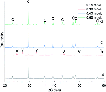 | ||
| Fig. 1 XRD image of CaCO3 crystal obtained with different initial CaCl2 and (NH4)2CO3 concentration. (Stirring speed = 400 rpm min−1; aging time: 10 min; C: calcite, V: vaterite.) | ||
FT-IR was used as a secondary characterization technique to identify the various initial CaCl2 and (NH4)2CO3 concentration in the crystals. The FTIR spectra of the CaCO3 crystals obtained in the 0.15 mol L−1, 0.45 mol L−1 and 0.60 mol L−1 initial CaCl2 and (NH4)2CO3 concentration are shown in Fig. 2a, c and d displays three characteristic peaks of calcite centered at 711 cm−1, 871 cm−1. As shown in Fig. 2a, c and d a single calcite phase can be confirmed by the appearance of characteristic υ2 band at 871 cm−1 and υ4 band at 711 cm−1. When the initial CaCl2 and (NH4)2CO3 concentration is 0.3 mol L−1 results in the occurrence of a new absorption peak located at 745 cm−1 and 1087 cm−1 (Fig. 2b), which is the fingerprint υ4 deformation band of CO32− in vaterite form, indicating the sample is vaterite phase CaCO3. According to the XRD and FTIR results, it can be concluded that the obtained product is calcite CaCO3 at 0.15 mol L−1, 0.45 mol L−1 and 0.60 mol L−1 initial CaCl2 and (NH4)2CO3 concentration, respectively, but the sample prepared at the condition of 0.30 mol L−1 initial CaCl2 and (NH4)2CO3 concentration are mainly vaterite and a little calcite CaCO3, the results are consistent with the XRD peak. When the initial CaCl2 and (NH4)2CO3 concentration is 0.15 mol L−1, the relative content of CaCO3 products obtained in the reaction system is relatively low, which is not conducive to the stability of vaterite so that with more stable thermodynamics calcite type CaCO3 products are obtained. When the initial CaCl2 and (NH4)2CO3 concentration is 0.45 and 0.60 mol L−1, since the initial solution concentration is too high so that the nucleation rate of CaCO3 is fast and vaterite can be formed in a short time.32 Since the reaction time does not change, vaterite products formed are converted into calcite through the process of dissolution and recrystallization.33 Therefore, When the initial CaCl2 and (NH4)2CO3 concentration is 0.30 mol L−1, a mixture composed mainly of vaterite and a small amount of calcite CaCO3 were obtained.
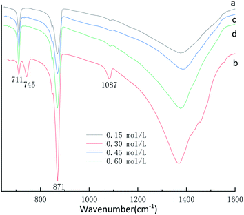 | ||
| Fig. 2 FTIR spectra of CaCO3 prepared with different initial CaCl2 and (NH4)2CO3 concentration. (Stirring speed = 400 rpm min−1; aging time: 10 min.) | ||
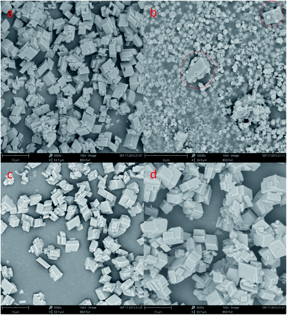
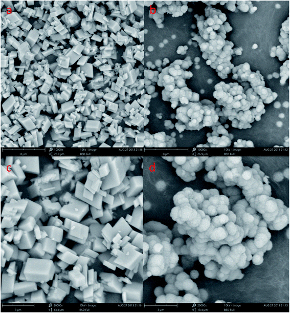
In order to understand the morphological and size changes at various initial CaCl2 and (NH4)2CO3 concentration of transformation, SEM images were taken for all the samples. It can be found in Fig. 3a, c and d that the CaCO3 is well-defined hexahedral crystals prepared with a size ranging from 8 to 10 μm under 0.15 mol L−1, 0.45 mol L−1 and 0.60 mol L−1 initial CaCl2 and (NH4)2CO3 concentration, respectively. Through Fig. 3b we can know that the sample prepared at the condition of 0.30 mol L−1 initial CaCl2 and (NH4)2CO3 concentration is 1 to 2 μm size spherical CaCO3, but the Fig. 3b indicated that the sample contains a certain amount of cubic calcite CaCO3 the particle size about 8 μm (red circle), it is consistent with the Fig. 1b XRD and Fig. 2b FTIR pattern. From Fig. 3a, c and d it can be seen the particle size of calcite particles has a little increases with concentration of reactants.
3.2 Effect of stirring speed on particle polymorph and morphology
A typical X-ray diffraction pattern of the CaCO3 particles prepared at different stirring speed is shown in Fig. 4. We through the analysis of Fig. 4a the XRD pattern confirmed that prepared CaCO3 is pure calcite at stirring speed 200 rpm min−1. However, as show that in Fig. 1b and 4b, the XRD pattern confirmed that prepared CaCO3 is vaterite and contains the peak of calcite (104) at stirring speed 400 and 600 rpm min−1. Calcite and vaterite contents of calcium carbonate products prepared at different stirring speeds were calculated using the method of eqn (4), the products prepared were mainly calcite with a content of 97.17% at 200 rpm min−1 but the products prepared were mainly vaterite with a content of 96.31% at 600 rpm min−1.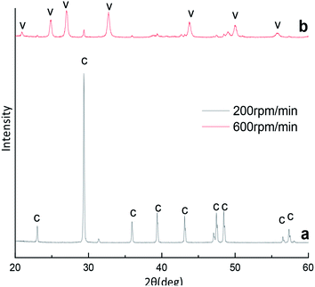 | ||
| Fig. 4 XRD image of CaCO3 crystal obtained with different stirring speed. (Ca2+: 0.3 mol L−1, (NH4)2CO3: 0.3 mol L−1; C: calcite, V: vaterite). | ||
FT-IR was used as a secondary characterization technique to identify the various stirring speed experimental conditions in the crystals. The FT-IR spectra of the CaCO3 crystals obtained in the various stirring speed experimental conditions are shown in Fig. 5 and Fig. 2b. Fig. 5a displays two characteristic peaks of calcite centered at 711 cm−1, 871 cm−1. Fig. 2b and 5b displays five characteristic peaks of centered at 711 cm−1, 745 cm−1, 871 cm−1, 1087 cm−1, the FTIR spectra (Fig. 2b and 5b) clearly showed typical bands at 745 cm−1, 871 cm−1, 1087 cm−1 which are attributed to the υ4, υ2, υ1, and υ3 modes of the crystalline vaterite phase, respectively. According to the XRD and FTIR results, it can be concluded that the obtained product is calcite CaCO3 at the 200 rpm min−1 experimental conditions, but the sample prepared at the condition of stirring speed 400 and 600 rpm min−1 are mainly vaterite and a little calcite CaCO3.
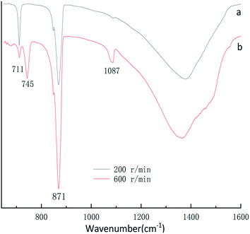 | ||
| Fig. 5 FTIR spectra of CaCO3 prepared with different stirring speed. (Ca2+: 0.3 mol L−1, (NH4)2CO3: 0.3 mol L−1; aging time: 10 min). | ||
The SEM shows a visible change in the morphology and polymorphism of the calcium carbonate crystals with the increase stirring speed. The morphology of the calcium carbonate particles obtained in the 200 and 600 rpm min−1 are presented in Fig. 6. We can concluded that the different stirring speed in the system (Fig. 6a–d) was an effective method to control the morphology of the CaCO3. Fig. 6a and c shows the typical rhombohedral calcite crystals with a size ranging from 5 to 8 μm that are formed under the 200 rpm min−1 experimental conditions. It can be observed in Fig. 3b and 6b, d that the CaCO3 crystals obtained at the 400 and 600 rpm min−1 were a spherical form. The Fig. 3b SEM showed that the precipitate consisted of a mixture of typical rhombohedral particles and spherical vaterite particles crystals at the 400 rpm min−1 experimental conditions. At the stirring speed of 600 rpm min−1, only the spherical vaterite crystal CaCO3 was obtained it can be seen in Fig. 6b and d. Combine the Fig. 4 XRD pattern and Fig. 5 FTIR spectrum show that with the increase of stirring speed, the prepared CaCO3 from calcite crystal convert to vaterite crystal. At the higher stirring speed of preparation condition, it is beneficial to the stability of vaterite polymorph and can also prevent vaterite conversion to calcite.
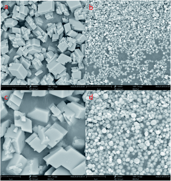 | ||
| Fig. 6 SEM image of CaCO3 crystal obtained different stirring speed. (a and c: 200 rpm min−1; b and d: 600 rpm min−1; Ca2+: 0.3 mol L−1, (NH4)2CO 3: 0.3 mol L−1; aging time: 10 min). | ||
Compared with calcite, vaterite has a higher specific surface energy, with relatively high surface energies were easily eliminated in the final morphology, so vaterite can quickly become more stable calcite and aragonite in an aqueous solution.34 At lower stirring speeds (200 rpm min−1), the reaction condition of CaCl2 and (NH4)2CO3 approached the equilibrium state, hence forming rhombohedral or pseudo-cubic calcite. With increasing of the stirring speeds, the probability of collision among the nano-particles in the immediate CaCO3 precipitates rose, such that the time is insufficient to make a choice for faces with specific surface energies in the formation of calcite phase via compact stacking, to say nothing of hexahedral crystals subsequently. As a result, the present case only crystallized to the metastable vaterite phase.35
3.3 Effect of Ca2+![[thin space (1/6-em)]](https://www.rsc.org/images/entities/h3_char_2009.gif) :
:![[thin space (1/6-em)]](https://www.rsc.org/images/entities/h3_char_2009.gif) CO32− ratio on particle polymorph and morphology
CO32− ratio on particle polymorph and morphology
The XRD phase and FTIR spectra compositions of as-synthesized CaCO3 with different Ca2+![[thin space (1/6-em)]](https://www.rsc.org/images/entities/char_2009.gif) :
:![[thin space (1/6-em)]](https://www.rsc.org/images/entities/char_2009.gif) CO32− molar ratio is displayed in Fig. 7 and 8. The Fig. 7 XRD result show that the strongest detected (hkl) peaks are at 2θ values of 24.90°, 27.04°, 32.82° and 29.40° corresponding to the following (hkl) indices: (110), (112), (114) and (104) represent the main peaks of (110), (112), and (114) planes of vaterite (PDF #33-0268) respectively, the (104) is among the main peaks of calcite(PDF #05-0586) polymorph of CaCO3. By the eqn (4) indicated the 52.99% calcite and 47.01% vaterite CaCO3 was obtained with Ca2+
CO32− molar ratio is displayed in Fig. 7 and 8. The Fig. 7 XRD result show that the strongest detected (hkl) peaks are at 2θ values of 24.90°, 27.04°, 32.82° and 29.40° corresponding to the following (hkl) indices: (110), (112), (114) and (104) represent the main peaks of (110), (112), and (114) planes of vaterite (PDF #33-0268) respectively, the (104) is among the main peaks of calcite(PDF #05-0586) polymorph of CaCO3. By the eqn (4) indicated the 52.99% calcite and 47.01% vaterite CaCO3 was obtained with Ca2+![[thin space (1/6-em)]](https://www.rsc.org/images/entities/char_2009.gif) :
:![[thin space (1/6-em)]](https://www.rsc.org/images/entities/char_2009.gif) CO32− ratio is 3
CO32− ratio is 3![[thin space (1/6-em)]](https://www.rsc.org/images/entities/char_2009.gif) :
:![[thin space (1/6-em)]](https://www.rsc.org/images/entities/char_2009.gif) 1, however, the 81.19% and 91.58% vaterite CaCO3 was obtained at Ca2+
1, however, the 81.19% and 91.58% vaterite CaCO3 was obtained at Ca2+![[thin space (1/6-em)]](https://www.rsc.org/images/entities/char_2009.gif) :
:![[thin space (1/6-em)]](https://www.rsc.org/images/entities/char_2009.gif) CO32− ratio are 1
CO32− ratio are 1![[thin space (1/6-em)]](https://www.rsc.org/images/entities/char_2009.gif) :
:![[thin space (1/6-em)]](https://www.rsc.org/images/entities/char_2009.gif) 3 and 1
3 and 1![[thin space (1/6-em)]](https://www.rsc.org/images/entities/char_2009.gif) :
:![[thin space (1/6-em)]](https://www.rsc.org/images/entities/char_2009.gif) 5, respectively. Fig. 8 displays four characteristic peaks of at 711 cm−1, 745 cm−1, 871 cm−1, 1087 cm−1, υ4 at 711 cm−1 is the peak of calcite, the peak of υ4 at 745 cm−1 and υ1 at 1087 cm−1 is vaterite, the peak of υ2 at 871 cm−1 is vaterite and calcite common peak. According to the Fig. 7 XRD pattern, CaCO3 obtained with different Ca2+
5, respectively. Fig. 8 displays four characteristic peaks of at 711 cm−1, 745 cm−1, 871 cm−1, 1087 cm−1, υ4 at 711 cm−1 is the peak of calcite, the peak of υ4 at 745 cm−1 and υ1 at 1087 cm−1 is vaterite, the peak of υ2 at 871 cm−1 is vaterite and calcite common peak. According to the Fig. 7 XRD pattern, CaCO3 obtained with different Ca2+![[thin space (1/6-em)]](https://www.rsc.org/images/entities/char_2009.gif) :
:![[thin space (1/6-em)]](https://www.rsc.org/images/entities/char_2009.gif) CO32− molar ratio was monoclinic crystal with coexistence of calcite phase and vaterite phase were formed which was further confirmed by Fig. 8 FTIR spectrum. However, when the Ca2+
CO32− molar ratio was monoclinic crystal with coexistence of calcite phase and vaterite phase were formed which was further confirmed by Fig. 8 FTIR spectrum. However, when the Ca2+![[thin space (1/6-em)]](https://www.rsc.org/images/entities/char_2009.gif) :
:![[thin space (1/6-em)]](https://www.rsc.org/images/entities/char_2009.gif) CO32− molar ratio are 3
CO32− molar ratio are 3![[thin space (1/6-em)]](https://www.rsc.org/images/entities/char_2009.gif) :
:![[thin space (1/6-em)]](https://www.rsc.org/images/entities/char_2009.gif) 1 the sample obtained main are calcite crystal CaCO3, when the Ca2+
1 the sample obtained main are calcite crystal CaCO3, when the Ca2+![[thin space (1/6-em)]](https://www.rsc.org/images/entities/char_2009.gif) :
:![[thin space (1/6-em)]](https://www.rsc.org/images/entities/char_2009.gif) CO32− molar ratio are 1
CO32− molar ratio are 1![[thin space (1/6-em)]](https://www.rsc.org/images/entities/char_2009.gif) :
:![[thin space (1/6-em)]](https://www.rsc.org/images/entities/char_2009.gif) 3 and 1
3 and 1![[thin space (1/6-em)]](https://www.rsc.org/images/entities/char_2009.gif) :
:![[thin space (1/6-em)]](https://www.rsc.org/images/entities/char_2009.gif) 5 the sample obtained main are vaterite crystal CaCO3 by Fig. 7 XRD pattern. It can be known that excess Ca2+ is beneficial to obtain calcite crystal CaCO3, on the contrary excess CO32− ion is beneficial to obtain vaterite crystal CaCO3.
5 the sample obtained main are vaterite crystal CaCO3 by Fig. 7 XRD pattern. It can be known that excess Ca2+ is beneficial to obtain calcite crystal CaCO3, on the contrary excess CO32− ion is beneficial to obtain vaterite crystal CaCO3.
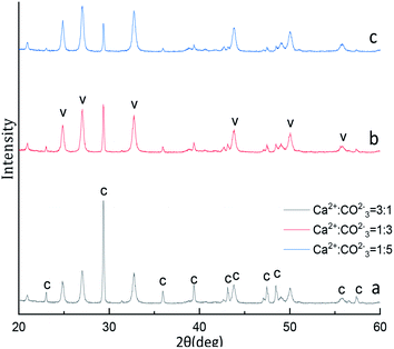 | ||
Fig. 7 XRD image of CaCO3 crystal obtained with different Ca2+![[thin space (1/6-em)]](https://www.rsc.org/images/entities/char_2009.gif) : :![[thin space (1/6-em)]](https://www.rsc.org/images/entities/char_2009.gif) CO32− ratios. (Stirring speed = 400 rpm min−1; aging time: 10 min; C: calcite, V: vaterite.) CO32− ratios. (Stirring speed = 400 rpm min−1; aging time: 10 min; C: calcite, V: vaterite.) | ||
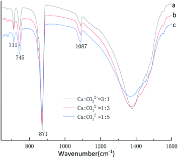 | ||
Fig. 8 FTIR spectra of CaCO3 prepared at different Ca2+![[thin space (1/6-em)]](https://www.rsc.org/images/entities/char_2009.gif) : :![[thin space (1/6-em)]](https://www.rsc.org/images/entities/char_2009.gif) CO32− ratio. (Stirring speed = 400 rpm min−1; aging time: 10 min.) CO32− ratio. (Stirring speed = 400 rpm min−1; aging time: 10 min.) | ||
In order to understand the morphological and size changes at various Ca2+![[thin space (1/6-em)]](https://www.rsc.org/images/entities/char_2009.gif) :
:![[thin space (1/6-em)]](https://www.rsc.org/images/entities/char_2009.gif) CO32− ratio, SEM images were taken for all the samples. We obtained spherical vaterite and the cubic calcite are clustered together can be found in Fig. 9a–c. The Fig. 9a–c showed that the precipitate consisted of a mixture of main typical spherical vaterite particles and a small amount cubic shaped calcite crystals at the Ca2+
CO32− ratio, SEM images were taken for all the samples. We obtained spherical vaterite and the cubic calcite are clustered together can be found in Fig. 9a–c. The Fig. 9a–c showed that the precipitate consisted of a mixture of main typical spherical vaterite particles and a small amount cubic shaped calcite crystals at the Ca2+![[thin space (1/6-em)]](https://www.rsc.org/images/entities/char_2009.gif) :
:![[thin space (1/6-em)]](https://www.rsc.org/images/entities/char_2009.gif) CO32−ratio 3
CO32−ratio 3![[thin space (1/6-em)]](https://www.rsc.org/images/entities/char_2009.gif) :
:![[thin space (1/6-em)]](https://www.rsc.org/images/entities/char_2009.gif) 1. By comparing the experimental results in Fig. 9d–f we can know that the prepared product is formed by the aggregation of products with multiple small particle sizes, after maturation, a number of spherical particles composed the aggregate vaterite and polyhedral diamond calcite were obtained, respectively. Fig. 9a–c illustrated that calcite were surrounded by the planar arrays of vaterite and the Fig. 9d–f show that the a part of the is CaCO3 polyhedral. According to Ostwald's law, it is believed that the metastable vaterite it is easy to transformation to calcite in the precipitation reaction.36 At different Ca2+
1. By comparing the experimental results in Fig. 9d–f we can know that the prepared product is formed by the aggregation of products with multiple small particle sizes, after maturation, a number of spherical particles composed the aggregate vaterite and polyhedral diamond calcite were obtained, respectively. Fig. 9a–c illustrated that calcite were surrounded by the planar arrays of vaterite and the Fig. 9d–f show that the a part of the is CaCO3 polyhedral. According to Ostwald's law, it is believed that the metastable vaterite it is easy to transformation to calcite in the precipitation reaction.36 At different Ca2+![[thin space (1/6-em)]](https://www.rsc.org/images/entities/char_2009.gif) :
:![[thin space (1/6-em)]](https://www.rsc.org/images/entities/char_2009.gif) CO32− ratio, the initial reaction was all vaterite CaCO3 prepared, as the reaction time goes on, some of the most unstable vaterite was carried out via Ostwald ripening converted into calcite as a whole. Because of the short reaction time, only part of the vaterite is converted into calcite, thus forming the calcium carbonate product mixed with calcite and vaterite as shown in Fig. 9. This result is consistent with the XRD pattern and FTIR spectra. Combined with Fig. 7 XRD pattern, Fig. 8 FTIR spectra and Fig. 9 SEM image, it can be concluded that when Ca2+ ions and CO32− ions are not in equal proportion, vaterite and calcite mixed phase CaCO3 can be formed.
CO32− ratio, the initial reaction was all vaterite CaCO3 prepared, as the reaction time goes on, some of the most unstable vaterite was carried out via Ostwald ripening converted into calcite as a whole. Because of the short reaction time, only part of the vaterite is converted into calcite, thus forming the calcium carbonate product mixed with calcite and vaterite as shown in Fig. 9. This result is consistent with the XRD pattern and FTIR spectra. Combined with Fig. 7 XRD pattern, Fig. 8 FTIR spectra and Fig. 9 SEM image, it can be concluded that when Ca2+ ions and CO32− ions are not in equal proportion, vaterite and calcite mixed phase CaCO3 can be formed.
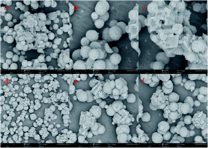 | ||
Fig. 9 SEM image of CaCO3 crystal obtained at different Ca2+![[thin space (1/6-em)]](https://www.rsc.org/images/entities/char_2009.gif) : :![[thin space (1/6-em)]](https://www.rsc.org/images/entities/char_2009.gif) CO32− ratio. (a–c: Ca2+ CO32− ratio. (a–c: Ca2+![[thin space (1/6-em)]](https://www.rsc.org/images/entities/char_2009.gif) : :![[thin space (1/6-em)]](https://www.rsc.org/images/entities/char_2009.gif) CO32− = 3 CO32− = 3![[thin space (1/6-em)]](https://www.rsc.org/images/entities/char_2009.gif) : :![[thin space (1/6-em)]](https://www.rsc.org/images/entities/char_2009.gif) 1; d–f,: Ca2+ 1; d–f,: Ca2+![[thin space (1/6-em)]](https://www.rsc.org/images/entities/char_2009.gif) : :![[thin space (1/6-em)]](https://www.rsc.org/images/entities/char_2009.gif) CO32− = 1 CO32− = 1![[thin space (1/6-em)]](https://www.rsc.org/images/entities/char_2009.gif) : :![[thin space (1/6-em)]](https://www.rsc.org/images/entities/char_2009.gif) 5; stirring speed = 400 rpm min−1; aging time: 10 min). 5; stirring speed = 400 rpm min−1; aging time: 10 min). | ||
3.4 Effect of aging time on particle polymorph and morphology
The experiments aiming at revealing the effect of aging time on the CaCO3 particle polymorph and morphology, the time-dependent shape evolution and phase transformation of intermediates were monitored by using XRD and SEM analysis. According to eqn (4), the content of the calcite and vaterite in the products are 24.99%, 9.07%, 4.56%, 15.62%, 12.07%, 22.23%, 18.17% and 75.01%, 90.93%, 95.44%, 84.38%, 87.93%, 77.77%, 81.83% at 5 s, 1 min, 5 min, 20 min, 30 min, 60 min and 120 min, respectively. The XRD patterns of the samples prepared showed in Fig. 10 that the intensity of the calcite (104) decreased with increasing aging time when the aging time is less than 20 min, but when the aging time is more than 20 min the intensity of the calcite (104) increased with increasing aging time. When the reaction time is less than 5 min in this short reaction time only the nucleating part of the crystal is completed at the reaction system so that prepared amorphous CaCO3 (through experiments it was verified that the product prepared when the reaction time was less than 5 min could penetrate the filter paper and it was speculated the product prepared was amorphous calcium carbonate). Thermodynamically the most unstable amorphous CaCO3 experienced the filtration and drying process is randomly converted into calcite and vaterite. Because calcite is more stable than vaterite, so that we can observed in Fig. 10a and b a stronger peak calcite (104) is formed. When the reaction time are 5–20 min that due to the reaction time is shorter and the obtained part of vaterite product is not completely stable, therefore in the process of filtering and drying part of vaterite conversion to calcite. With the extension of reaction time, the vaterite crystal has been completed so that the calcite (104) peak strength decreased. When the reaction time exceeds 20 min, we know vaterite with poor thermodynamic stability so that in the reaction mother liquor environment is can slowly converted into stable and finally we found the strength of calcite (104) peak increases with the increase of reaction time.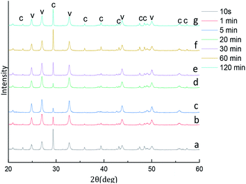 | ||
| Fig. 10 XRD image of CaCO3 crystal obtained at different aging time. (Stirring speed = 400 rpm min−1; Ca2+: 0.3 mol L−1, (NH4)2CO3: 0.3 mol L−1; C: calcite, V: vaterite). | ||
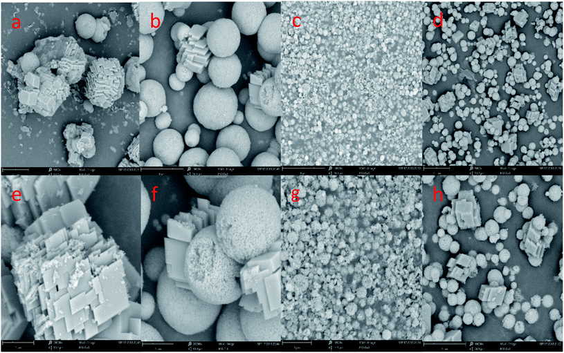
In order to investigate the formation mechanism of CaCO3, we changed the reaction time without changing other experimental conditions. Fig. 11 shows a representative SEM image of CaCO3 particles were obtained by different aging time. It can be seen in Fig. 11a and e existed is the multilayer hexahedral crystals of CaCO3 and is the spherical crystals of CaCO3 in large quantity (Fig. 11a). Further increase in the aging time to 1 min this can be ascribed to the existence of a mount of spherical crystals of CaCO3 and small amounts of polyhedron hexahedral crystal in the precipitates (Fig. 11b and f). A aging time 10 and 20 min mainly afforded microspheres in the precipitates of size in the range of 1–2 μm (Fig. 1b and 11c, g). As the aging time went up to 60 min, a large quantity spherical crystals of CaCO3 aggregate and a small number of the precipitates had transformed to pseudo-cubic structures or randomly aggregated rhomboherdal as shown in Fig. 11d and h.
Through the analysis of Fig. 10 XRD pattern and Fig. 11 SEM image, it is obvious that sample are mainly composed of calcite particles; meanwhile samples main contain vaterite and small amount of a mixture of calcite particles prepared from 5 min to 10 min aging time. With the increase of aging time from 10 s to 20 min, the reflection of calcite decreases gradually, and vaterite progressively dominates. However, with the extension of aging time to 60 min, the content of vaterite decreased.
3.5 Effect of adding mode on particle polymorph and morphology
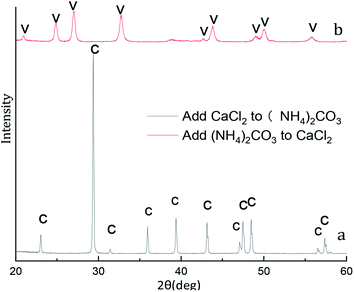
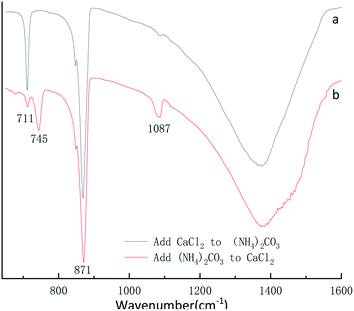
X-ray diffraction pattern of the CaCO3 particles prepared at different adding mode is shown in Fig. 12. The XRD result in Fig. 12a indicated that the peak are at 2θ values of 23.1°, 29.4°, 36.0°, 39.4°, 43.2°, 47.5°, 48.5°correspond to the (012), (104), (110), (113), (202), (018), (116), (122), (214), (300) are pure crystallographic planes of calcite (PDF #05-0586) without impurities. As can be seen in the sample Fig. 12b the strongest detected (hkl) peaks are at 2θ values of 24.9°, 27.1°, 32.8°, 38.6°, 44.0°, 49.1°, 50.2°and 55.9° indicates that the composition of the CaCO3 are pure phase of vaterite (PDF #33-0268) without impurities. Different of added mode lead to excessive Ca2+ and CO32− in the reaction system so that two different crystalline calcium carbonate products are obtained.37By the eqn (4) computed value of calcite approximately (100%) and vaterite approximately (100%) revealed that the products were pure phase of calcite and vaterite was consistent with that of XRD in Fig. 12a and b, respectively. As shown from Fig. 13a, the calcite characteristic bands of υ4 at 711 cm−1 and υ2 at 871 cm−1 appeared in the above samples. Also, vaterite characteristic bands of υ4 at 745 cm−1 and υ1 at 1090 cm−1 can be observed in Fig. 13b. The Fig. 13 FTIR spectra results are consistent with those of Fig. 12 XRD pattern.
The SEM results show that CaCl2 and (NH4)2CO3 adding mode influence the CaCO3 morphologies more obviously when other experimental conditions are the same in Fig. 14. In Fig. 14a and c shows some rhombohedral particle with a size ranging from 1 to 3 μm were produced when was CaCl2 dropwise added into (NH4)2CO3. However, as shown in Fig. 14b and d, multiple micro/nanosized spherical particles by Ostwald ripening tend to grow larger and become nonuniform 5 to 8 μm aggregates of spherical particles when solution (NH4)2CO3 was dropwise added into solution CaCl2. Combined with Fig. 12 XRD pattern, Fig. 13 FTIR spectra and Fig. 14 SEM image, it can be concluded that when CaCl2 dropwise added into (NH4)2CO3, only calcite phase CaCO3 can be formed, when (NH4)2CO3 add into CaCl2, only vaterite phase CaCO3 can be formed.
4. Conclusions
Hexahedral calcite crystals CaCO3 prepared with a size ranging from 8 to 10 μm have been obtained in 0.15 mol L−1, 0.45 mol L−1 and 0.60 mol L−1 initial CaCl2 and (NH4)2CO3 concentration and 1 to 2 μm size spherical vaterite crystals CaCO3 the sample prepared at the condition of 0.30 mol L−1 initial CaCl2 and (NH4)2CO3 concentration. The obtained product is calcite CaCO3 at the 200 rpm min−1 experimental conditions, but the sample prepared at the condition of stirring speed 400 and 600 rpm min−1 is micro/nano level vaterite CaCO3. When Ca2+ ions and CO32− ions are not in equal proportion, vaterite and calcite mixed phase CaCO3 can be formed. With the extension of aging time, the prepared products first from calcite crystal convert to vaterite crystal CaCO3, and with the further extension of aging time, the content of CaCO3 vaterite decreased. When CaCl2 add into (NH4)2CO3, only calcite phase CaCO3 can be formed, when (NH4)2CO3 add into CaCl2, only vaterite phase CaCO3 can be formed. These results could offer fundamental insight into how to control the size and polymorphism of CaCO3 prepared by steamed ammonia liquid waste, eventually allowing large-scale industrial preparation the creation of value-added CaCO3 products and part of the experimental results will be applied to the recovery and utilization of steam ammonia waste liquid in Western Mining Group Co., Ltd.Conflicts of interest
There are no conflicts to declare.Acknowledgements
This work was partially supported by the National Key Research and Development Program of China (2018YFC1903805) and Major Science and Technology Projects of Qinghai Province (2020-GX-A1).References
- T. D. Lam, T. V. Hoang, D. T. Quang and J. S. Kim, Mater. Sci. Eng., A, 2009, 501, 87–93 CrossRef.
- F. Karakaş, B. V. Hassas and M. S. Çelik, Prog. Org. Coat., 2015, 83, 64–70 CrossRef.
- J. Shen, Z.-Q. Song, X.-R. Qian and F. Yang, Carbohydr. Polym., 2010, 81, 545–553 CrossRef CAS.
- A. Said, H.-P. Mattila, M. Järvinen and R. Zevenhoven, Appl. Energy, 2013, 112, 765–771 CrossRef CAS.
- D. B. Trushina, T. V. Bukreeva, M. V. Kovalchuk and M. N. Antipina, Mater. Sci. Eng., C, 2014, 45, 644–658 CrossRef CAS PubMed.
- A. Sarkar and S. Mahapatra, Cryst. Growth Des., 2010, 10, 2129–2135 CrossRef CAS.
- M. Ni and B. D. Ratner, Surf. Interface Anal., 2008, 40, 1356–1361 CrossRef CAS PubMed.
- T. Beuvier, B. Calvignac, G. J.-R. Delcroix, M. K. Tran, S. Kodjikian, N. Delorme, J.-F. Bardeau, A. Gibauda and F. Boury, J. Mater. Chem., 2011, 21, 9757–9761 RSC.
- I. Udrea, C. Capat, E. A. Olaru, R. Isopescu, M. Mihai, C. D. Mateescu and C. Bradu, Ind. Eng. Chem. Res., 2012, 51, 8185–8193 CrossRef CAS.
- Y.-H. Lai, L.-S. Chen, W.-C. Bao, Y.-H. Ren, Y.-X. Gao, Y.-W. Yin and Y.-F. Zhao, Cryst. Growth Des., 2015, 15, 1194–1200 CrossRef CAS.
- G. Yuan, X.-F. Chen, X. Li, Q.-M. Liang, G.-H. Miao and B. Yuan, Powder Technol., 2015, 284, 253–256 CrossRef CAS.
- P.-Y. Chen, H.-H. Ma, Y. Xu and Z.-W. Shen, Int. J. Mater. Res., 2017, 108, 600–606 CrossRef CAS.
- Z.-X. Zhao, L. Zhang, H.-X. Dai, Y.-C. Du, X. Meng, R.-Z. Zhang, Y.-X. Liu and J.-G. Deng, Microporous Mesoporous Mater., 2011, 138, 191–199 CrossRef CAS.
- C. Qi, Y.-J. Zhu and F. Chen, ACS Appl. Mater. Interfaces, 2014, 6, 4310–4320 CrossRef CAS PubMed.
- R.-J. Qi and Y.-J. Zhu, J. Phys. Chem. B, 2006, 110, 8302–8306 CrossRef CAS PubMed.
- Y.-X. Chen, X.-B. Ji and X. B. Wang, J. Cryst. Growth, 2010, 312, 3191–3197 CrossRef CAS.
- J. A. Juhasz-Bortuzzo, B. Myszka, R. Silva and A. R. Boccaccini, Cryst. Growth Des., 2017, 5, 2351–2356 CrossRef.
- L.-P. Liu, D.-W. Fan, H.-Z. Mao, X. Fang and J.-C. Hao, J. Colloid Interface Sci., 2007, 306, 154–160 CrossRef CAS PubMed.
- R. K. Pai and S. Pillai, CrystEngComm, 2008, 10, 865–872 RSC.
- Z.-G. Wu, Y. Guo, J. Wang and Y.-R. Jia, Int. J. Mater. Res., 2017, 108, 245–248 CrossRef CAS.
- L. Amer, S. Ouheniaa, I. Belabbas and D. Chateigner, J. Cryst. Growth, 2018, 501, 49–59 CrossRef CAS.
- H. Casanova and L. P. Higuita, Chem. Eng. J., 2011, 175, 569–578 CrossRef CAS.
- Y.-S. Han, G.-W. Hadiko, M. Fuji and M. Takahashi, J. Eur. Ceram. Soc., 2006, 26, 843–847 CrossRef CAS.
- Y.-S. Wang, Y.-X. Moo, Ch-P. Chen, P. Gunawan and R. Xu, J. Colloid Interface Sci., 2010, 352, 393–400 CrossRef CAS PubMed.
- Y. Mori, T. Enomae and A. Isogai, Mater. Sci. Eng., C, 2009, 29, 1409–1414 CrossRef CAS.
- M. Santos Rafael, P. Ceulemans and T. V. Gerven, Chem. Eng. Res. Des., 2012, 90, 715–725 CrossRef.
- H.-X. Guo, P.-Z. Sun, Z.-P. Qin, L.-L. Shan, G.-J. Zhang, S.-P. Cui and Y.-C. Liang, Eur. J. Inorg. Chem., 2014, 1001–1009 CrossRef CAS.
- A. T. Nagaraja, S. Pradhan and M. J. McShane, J. Colloid Interface Sci., 2014, 418, 366–372 CrossRef CAS PubMed.
- R. Ševčík, M. Pérez-Estébanez, A. Viani, P. Šašek and P. Mácová, Powder Technol., 2015, 284, 265–271 CrossRef.
- C. M. Oral and B. Ercan, Powder Technol., 2018, 339, 781–788 CrossRef CAS.
- H.-C. Dang, Z.-Z. Xu, Z.-S. Chen, W.-L. Wu, J. Feng, Y.-Y. Sun, F.-C. Jin, J. Li and F. Ge, Cryst. Res. Technol., 2019, 243, 1–7 Search PubMed.
- C. G. Kontoyannis and N. V. Vagenas, Analyst, 2000, 125, 251–255 RSC.
- S. Karthika, T. K. Radhakrishnan and P. Kalaichelvi, Cryst. Growth Des., 2016, 16, 6663–6681 CrossRef CAS.
- L. A. Estroff and D. R. Hamilton, Chem. Mater., 2001, 13, 3227–3235 CrossRef CAS.
- F.-W. Yan, S.-F. Zhang, C.-Y. Guo, X.-H. Zhang, G.-C. Chen, F. Yan and G.-Q. Yuan, Cryst. Res. Technol., 2009, 44, 725–728 CrossRef CAS.
- X.-d. Yang, G.-y. Xu, Y.-j. Chen, F. Wang, H.-z. Mao, W.-P. Sui, Y. Bai and H.-j. Gong, J. Cryst. Growth, 2009, 311, 4558–4569 CrossRef CAS.
- S. Kirboga and O. Mualla, Powder Technol., 2013, 24, 95–104 CrossRef.
| This journal is © The Royal Society of Chemistry 2020 |


