
 Open Access Article
 This Open Access Article is licensed under a Creative Commons Attribution-Non Commercial 3.0 Unported Licence
Continuous syntheses of carbon-supported Pd and Pd@Pt core–shell nanoparticles using a flow-type single-mode microwave reactor†
Masato Miyakawa *a,
Norihito Hiyoshia,
Hidekazu Kodab,
Kenichi Watanabeb,
Hideki Kunigamib,
Hiroshi Kunigamib,
Akira Miyazawaa and
Masateru Nishioka*a
*a,
Norihito Hiyoshia,
Hidekazu Kodab,
Kenichi Watanabeb,
Hideki Kunigamib,
Hiroshi Kunigamib,
Akira Miyazawaa and
Masateru Nishioka*a
aNational Institute of Advanced Industrial Science and Technology, AIST, 4-2-1, Nigatake, Miyagino-ku, Sendai, 983-8551, Japan. E-mail: masato-miyakawa@aist.go.jp; m-nishioka@aist.go.jp
bShinko Kagaku Kogyosyo Co., Ltd., 1544-19, Mashimori, Koshigaya-shi, Saitama 343-0012, Japan
First published on 12th February 2020
Abstract
Continuous syntheses of carbon-supported Pd@Pt core–shell nanoparticles were performed using microwave-assisted flow reaction in polyol to synthesize carbon-supported core Pd with subsequent direct coating of a Pt shell. By optimizing the amount of NaOH, almost all Pt precursors contributed to shell formation without specific chemicals.
Continuous flow syntheses have attracted attention as a powerful method for organic, nanomaterial, and pharmaceutical syntheses because of various features that produce benefits in terms of efficiency, safety, and reduction of environmental burdens.1–7 Advances of homogeneous heating and mixing techniques in continuous flow reactors have engendered further developments for precise reaction control, which is expected to create innovative materials through combination with multiple-step flow syntheses.
Microwave (MW) dielectric heating has been recognized as a promising methodology for continuous flow syntheses because rapid or selective heating raises the reaction rate and product yield.8–18 For the last two decades, most MW apparatus has been batch-type equipped with a stirring mechanism in a multi-mode cavity. Therefore, conventionally used MW-assisted flow reactors have been mainly of the modified batch-type. Results show that the electromagnetic field distribution can be spatially disordered, causing inhomogeneous heating of the reactor.19–25 Improvements of reactors suitable for flow-type work have been studied actively in recent years to improve their energy efficiency and to make irradiation of MW more homogeneous.26–37
We originally designed a MW flow reactor system that forms a homogeneous heating zone through generation of a uniform electromagnetic field in a cylindrical single-mode MW cavity.26,30 The temperatures of flowing liquids in the reactor were controlled precisely via the resonance frequency auto-tracking function. Continuous flow syntheses of metal nanoparticle, metal-oxide, and binary metal core–shell systems with uniform particle size have been achieved using our MW reactor system.26,38,39 Furthermore, large-scale production necessary for industrial applications can be achieved through integration of multiple MW reactors.30
Carbon-supported metal catalysts are widely used in various chemical transformations and fine organic syntheses. Particularly, binary metal systems such as Pd@Pt core–shell nanoparticles have attracted considerable interest for electro-catalysis in polymer electrolyte membrane fuel cells (PEMFC) because of their enhanced oxygen reduction activity compared to a single-use Pt catalyst. Binary metal systems also contribute to minimization of the usage of valuable Pt.40–51 Earlier studies of carbon-supported Pd@Pt syntheses involved multiple steps of batch procedures such as separation, washing and pre-treatment of core metal nanoparticles, coating procedures of metal shells, and dispersion onto carbon supports. Flow-through processes generally present advantages over batch processes in terms of simplicity and high efficiency in continuous material production.
We present here a continuous synthesis of carbon-supported Pd and Pd@Pt core–shell nanoparticles as a synthesis example of a carbon-supported metal catalyst using our MW flow reactor. This system incorporates the direct transfer of a core metal dispersion into a shell formation reaction without isolation. Nanoparticle desorption is prevented by nanoparticle synthesis directly on a carbon support. The presence of protective agents that are commonly used in nanoparticle syntheses, such as poly(N-vinylpyrrolidone), can limit the chemical activity of the catalyst. Nevertheless, this system requires no protective agent. Moreover, this system is a simple polyol synthesis that uses no strong reducing agent. It therefore imposes little or no environmental burden. For this study, the particle size and distribution of metals in Pd and Pd@Pt core–shell nanoparticles were characterized using TEM, HAADF-STEM observations, and EDS elemental mapping. From electrochemical measurements, the catalytic performance of Pd@Pt core–shell nanoparticles was evaluated.
A schematic view of the process for the continuous synthesis of carbon-supported Pd@Pt core–shell nanoparticles is presented in Fig. 1. Details of single-mode MW flow reactor are described in ESI.† We attempted to conduct a series of reactions coherently in a flow reaction system, i.e., MW-assisted flow reaction for the synthesis of carbon supported core Pd nanoparticles with subsequent deposition of the Pt shell. Typically, a mixture containing Na2[PdCl4] (1–4 mM) in ethylene glycol (EG), carbon support (Vulcan XC72, 0.1 wt%), and an aqueous NaOH solution were prepared. This mixture was introduced continuously into the PTFE tube reactor placed in the center of the MW cavity. Here, EG works as the reaction solvent as well as the reducing agent that converts Pd(II) into Pd(0) nanoparticles. The MW heating temperature was set to 100 °C with the flow rate of 80 ml h−l, which corresponds to residence time of 4 s. The carbon-supported Pd nanoparticles were transferred directly to the Pt shell formation process without particle isolation. The dispersed solution was introduced into a T-type mixer and was mixed with a EG solution of H2[PtCl6]·6H2O (10 mM). The molar ratio of Pd![[thin space (1/6-em)]](https://www.rsc.org/images/entities/char_2009.gif) :Pt was fixed to 1:1. Subsequently, after additional aqueous NaOH solution was mixed at the second T-mixer, the reaction mixture was taken out of the mixer and was let to stand at room temperature (1–72 h) for Pt shell growth.
:Pt was fixed to 1:1. Subsequently, after additional aqueous NaOH solution was mixed at the second T-mixer, the reaction mixture was taken out of the mixer and was let to stand at room temperature (1–72 h) for Pt shell growth.
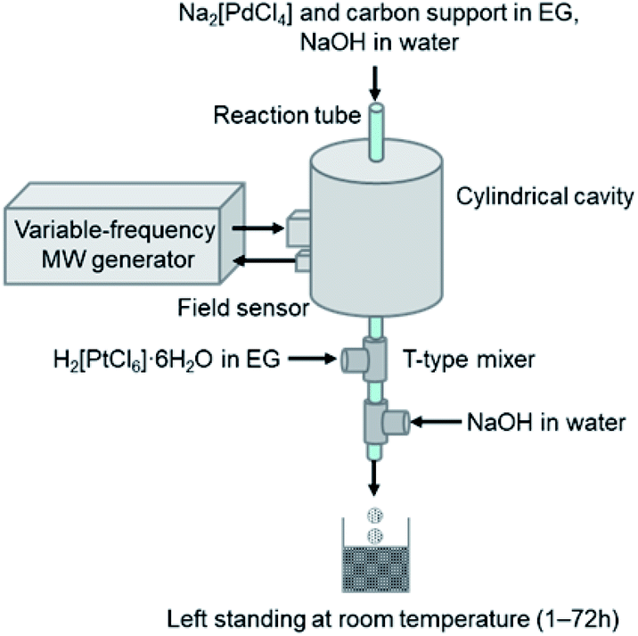 | ||
| Fig. 1 Schematic showing continuous synthesis of carbon-supported Pd and Pd@Pt core–shell nanoparticles. The Pd nanoparticles were dispersed on the carbon support by MW heating of the EG solution. The solution was then transferred directly to Pt shell formation. | ||
Rapid formation of Pd nanoparticles with average size of 3.0 nm took place at the carbon-support surface during MW heating in the tubular reactor (Fig. 2a). Most of the Pd(II) precursor was converted instantaneously to Pd(0) nanoparticles and was well dispersed over the carbon surface. Fig. 2b shows the time profile of the outlet temperature and applied MW power during continuous synthesis of carbon-supported Pd nanoparticles. The solution temperature rose instantaneously, reaching the setting temperature in a few seconds. This temperature was maintained with high precision (±2 °C) by the continuous supply of ca. 18 W microwave power. No appreciable deposition of metal was observed inside of the PTFE tube. It is noteworthy that Pd of 98% or more was supported on carbon by heating for 4 s at 100 °C from ICP-OES measurement. Our earlier report described continuous polyol (EG) synthesis of Pd nanoparticles as nearly completed with 6 s at 200 °C.39 The reaction temperature in polyol synthesis containing the carbon was considerably low, suggesting that selective reduction reaction occurs on the carbon surface, which is a high electron donating property.
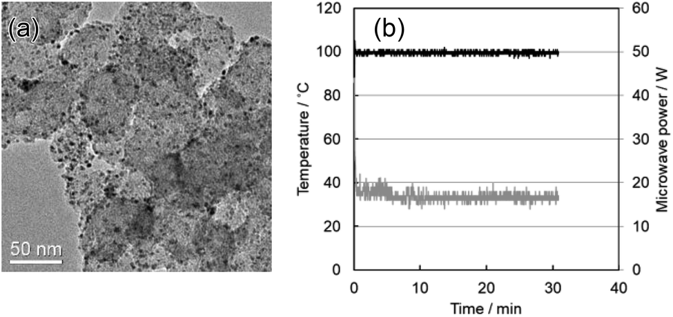 | ||
| Fig. 2 (a) TEM image of carbon-supported Pd nanoparticles synthesized using the MW flow reactor. The average particle size was 3.0 nm. (b) The time profile of the temperature at the reactor outlet and applied microwave power during continuous synthesis of carbon-supported Pd nanoparticles. Na2[PdCl4] = 2 mM, NaOH = 10 mM. | ||
The concentrations of Na2[PdCl4] precursor and NaOH affect the Pd nanoparticle size. Results show that the Pd particle size increased as the initial concentration of Na2[PdCl4] increased (Fig. S1a and b†). Change of NaOH concentration exerted a stronger influence on the particle size. Nanoparticles of 12.3 nm were observed without addition of NaOH, whereas 2.6 nm size particles were deposited at the concentration of 20 mM (Fig. S1c and d†). The higher NaOH concentration led to instantaneous nucleation and rapid completion of reduction. The Pd nanoparticle surface is equilibrated with Pd–O− and Pd–OH depending on the NaOH concentration. The surface is more negative at high concentrations of NaOH because of the increase of the number of Pd–O−, which inhibits the mutual aggregation and further particle growth. Furthermore, to control the Pd nanoparticle morphology, we conducted synthesis by adding NaBr, which has been reported as effective for cubic Pd nanoparticle synthesis.52 However, because reduction of the Pd precursor derives from electron donation from both the polyol and the carbon support, morphological control was not achieved (Fig. S2†). That finding suggests that morphological control is difficult to achieve by adding surfactant agents to the polyol.
For Pt shell formation, carbon supported Pd nanoparticles (3.0 nm average particle size) were mixed with H2[PtCl6]·6H2O solution with the molar ratio of Pd:Pt = 1:1. Then additional NaOH solution was mixed. As described in earlier reports,39 alkaline conditions under which base hydrolysis and reduction of [PtCl6]2− to [Pt(OH)4]2− takes place are necessary for effective Pt shell formation. It is noteworthy that the added Pt precursor was almost entirely supported on carbon within 24 h in cases where an appropriate amount of additional NaOH (5 mM) was mixed by the second T-mixer (Fig. 3a). However, for 10 mM, nucleation and growth of single Pt nanoparticles were enhanced in place of core–shell formation. Consequently, a mixture of Pd@Pt and single Pt nanoparticles was formed on the carbon support (Fig. 3b). Very fine Pt nanoparticles were observed in the supernatant solution.
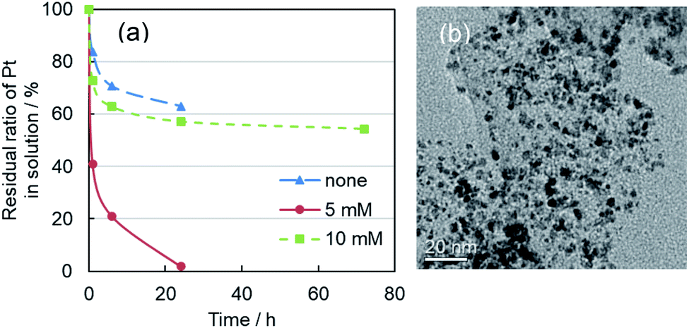 | ||
| Fig. 3 (a) Time profiles of residual ratio of Pt in the mixed solutions. Horizontal axis was left standing time. Carbon-support in the mixed solution after added the Pt precursor was precipitated by centrifugation. The supernatant solution was measured by ICP-OES. Concentrations of additional NaOH were 0, 5, and 10 mM. (b) TEM image of carbon-supported Pd@Pt core–shell nanoparticles. The synthesis conditions of Pd nanoparticles were Na2[PdCl4] (2 mM) and NaOH (10 mM). The molar ratio of Na2[PdCl4]:H2[PtCl6]·6H2O was 1:1, and additional NaOH concentration was 10 mM. After left standing for 72 h, the mixture of Pd@Pt and single Pt nanoparticles (1–2 nm) was formed on carbon-support. | ||
Fig. 4a portrays a TEM image of carbon supported Pd@Pt core–shell nanoparticles. The average particle size of Pd@Pt core–shell nanoparticles was 3.6 nm after being left to stand for 24 h: larger than the initial Pd nanoparticles (3.0 nm). Fig. 4b shows the HAADF-STEM image of Pd@Pt core–shell nanoparticles supported on carbon. The core–shell structure of the particles can be ascertained from the contrast of the image. The Z-contrast image shows the presence of brighter shells over darker cores. Actually, the contrast is strongly dependent on the atomic number (Z) of the element.53 The Z values of Pt (Z = 78) and Pd (Z = 46) differ considerably. Therefore, the image shows the formation of Pd@Pt core–shell structure with the uniform elemental distribution. Elemental mapping images by STEM-EDS show that both Pd and Pt metals were present in all the observed nanoparticles (Fig. 4c). Based on the atomic ratio (Pd:Pt = 49:51), they show good agreement with the designed values. The Pt shell thickness was estimated as about 0.6 nm, which corresponds to 2–3 atomic layer thickness of Pt encapsulating the Pd core metal, indicating good agreement with Fig. 4b image. For an earlier study, uniform Pt shells were formed by dropwise injection of the Pt precursor solution because the Pt shell growth rate differs depending on the crystal plane of the Pd nanoparticle.46 For more precise control of shell thickness in our system, the Pt precursor solution should be mixed in multiple steps.
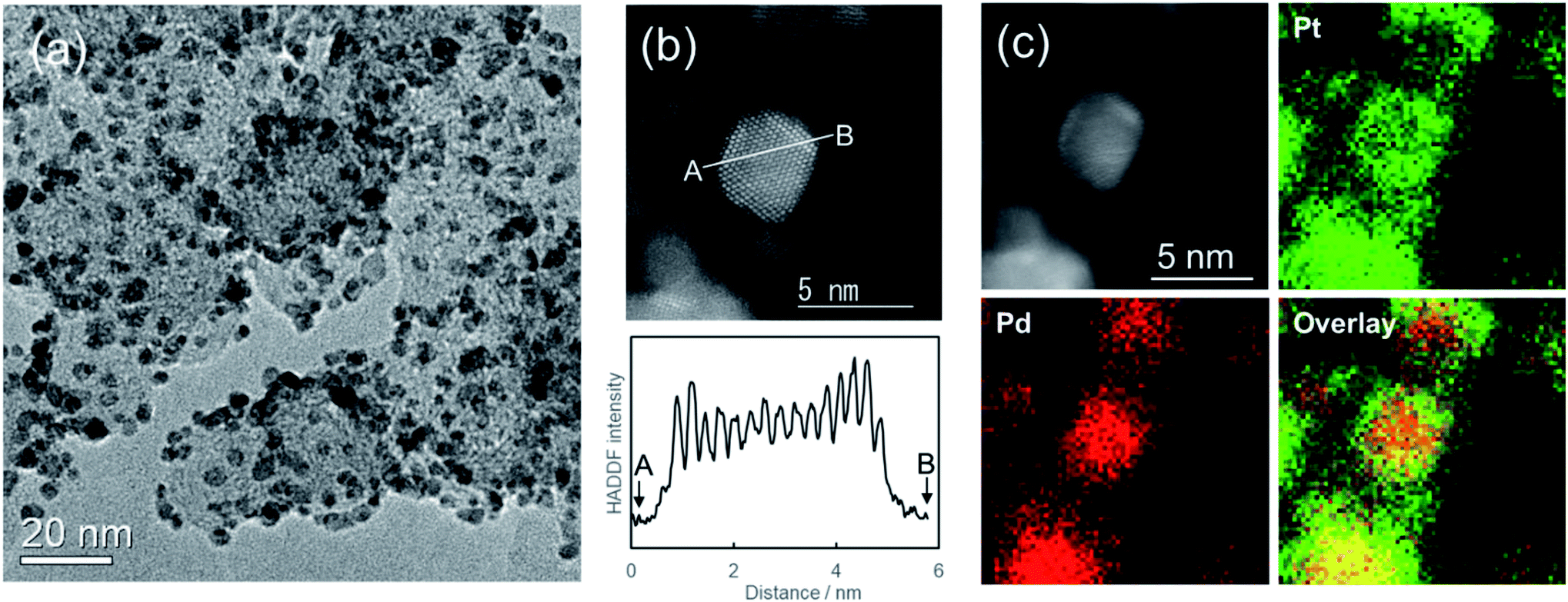 | ||
| Fig. 4 (a) TEM image and (b) HAADF-STEM image of carbon-supported Pd@Pt core–shell nanoparticles and the line profile of contrast. (c) Elemental mapping image of carbon-supported Pd@Pt core–shell nanoparticles, where Pd and Pt elements are displayed respectively as red and green. The EDS atomic ratio of Pd:Pt was 49:51. The synthesis conditions of Pd nanoparticles were Na2[PdCl4] (2 mM) and NaOH (10 mM). The molar ratio of Na2[PdCl4]:H2[PtCl6]·6H2O was 1:1. The concentration of additional NaOH were 5 mM. It was left standing for 24 h. | ||
A comparison of the catalytic performance of the carbon-supported Pd@Pt core–shell and Pt nanoparticles is shown in Fig. S3.† For this experiment, carbon-supported Pt nanoparticles with Pt 2 mM were prepared as a reference catalyst using a similar synthetic method. The initial Pt mass activities of the carbon-supported Pd@Pt and Pt nanoparticles were, respectively, 0.39 and 0.24 A mgPt−1, improving by the core–shell structure. In addition, durability tests for carbon-supported Pd@Pt nanoparticles show that the reduction rate of Pt mass activity after 5000 cycles was only 2%. The catalytic activities of carbon-supported Pd@Pt nanoparticles were superior in terms of durability, suggesting that the Pt shell was firmly formed.
Conclusions
Continuous syntheses of carbon-supported Pd and Pd@Pt core–shell nanoparticles were demonstrated by integration of a series of reactions including MW-assisted polyol processes for core Pd nanoparticle formation, followed by coating with a Pt shell. Uniform core Pd nanoparticles (3.0 nm) were obtained continuously through 4 s of residence time. The NaOH concentration affected the Pt shell formation reaction. The Pt shell thickness of 2–3 atomic layers showed good agreement with the HAADF-STEM image. This variable-frequency single-mode MW reactor system is a promising candidate for the continuous production of carbon-supported metal nanoparticles. It is also a useful heating method for continuous flow syntheses in general.Conflicts of interest
The authors have no conflict to declare.Acknowledgements
We would like to thank Ms. Chizuru Shigaraki for assisting with experiments. We also thank Dr Toshishige M. Suzuki for useful discussions and Ryowa Electronics Co., Ltd. for technical support of the MW reactor.Notes and references
- P. Watts and S. J. Haswell, Chem. Soc. Rev., 2005, 34, 235–246 RSC.
- A. Abou-Hassan, O. Sandre and V. Cabuil, Angew. Chem., Int. Ed., 2010, 49, 6268–6286 CrossRef CAS PubMed.
- R. M. Myers, D. I. Fitzpatrick, R. M. Turner and S. V. Ley, Chem.–Eur. J., 2014, 20, 12348–12366 CrossRef CAS PubMed.
- T. Tsubogo, H. Oyamada and S. Kobayashi, Nature, 2015, 520, 329–332 CrossRef CAS PubMed.
- B. Gutmann, D. Cantillo and C. O. Kappe, Angew. Chem., Int. Ed., 2015, 54, 6688–6728 CrossRef CAS.
- M. B. Plutschack, B. Pieber, K. Gilmore and P. H. Seeberger, Chem. Rev., 2017, 117, 11796–11893 CrossRef CAS.
- J. A. Darr, J. Zhang, N. M. Makwana and X. Weng, Chem. Rev., 2017, 117, 11125–11238 CrossRef CAS.
- R. Gedye, F. Smith, K. Westaway, H. Ali, L. Baldisera, L. Laberge and J. Rousell, Tetrahedron Lett., 1986, 27, 279–282 CrossRef CAS.
- S. Caddick, Tetrahedron, 1995, 51, 10403–10432 CrossRef CAS.
- S. A. Galema, Chem. Soc. Rev., 1997, 26, 233–238 RSC.
- R. S. Varma, Green Chem., 1999, 1, 43–55 RSC.
- K. J. Rao, B. Vaidhyanathan, M. Ganguli and P. A. Ramakrishnan, Chem. Mater., 1999, 11, 882–895 CrossRef CAS.
- P. Lidström, J. Tierney, B. Wathey and J. Westman, Tetrahedron, 2001, 57, 9225–9283 CrossRef.
- M. Larhed, C. Moberg and A. Hallberg, Acc. Chem. Res., 2002, 35, 717–727 CrossRef CAS PubMed.
- C. O. Kappe, Angew. Chem., Int. Ed., 2004, 43, 6250–6284 CrossRef CAS.
- D. Dallinger and C. O. Kappe, Chem. Rev., 2007, 107, 2563–2591 CrossRef CAS.
- I. Bilecka and M. Niederberger, Nanoscale, 2010, 2, 1358–1374 RSC.
- M. Baghbanzadeh, L. Carbone, P. D. Cozzoli and C. O. Kappe, Angew. Chem., Int. Ed., 2011, 50, 11312–11359 CrossRef CAS PubMed.
- J. D. Ferguson, Mol. Diversity, 2003, 7, 281–286 CrossRef CAS PubMed.
- M. C. Bagley, R. L. Jenkins, M. C. Lubinu, C. Mason and R. Wood, J. Org. Chem., 2005, 70, 7003–7006 CrossRef CAS.
- T. N. Glasnov and C. O. Kappe, Macromol. Rapid Commun., 2007, 28, 395–410 CrossRef CAS.
- J. D. Moseley and E. K. Woodman, Org. Process Res. Dev., 2008, 12, 967–981 CrossRef CAS.
- M. H. C. L. Dressen, B. H. P. van de Kruijs, J. Meuldijk, J. A. J. M. Vekemans and L. A. Hulshof, Org. Process Res. Dev., 2010, 14, 351–361 CrossRef CAS.
- F. Bergamelli, M. Iannelli, J. A. Marafie and J. D. Moseley, Org. Process Res. Dev., 2010, 14, 926–930 CrossRef CAS.
- T. N. Glasnov and C. O. Kappe, Chem.–Eur. J., 2011, 17, 11956–11968 CrossRef CAS.
- M. Nishioka, M. Miyakawa, H. Kataoka, H. Koda, K. Sato and T. M. Suzuki, Nanoscale, 2011, 3, 2621–2626 RSC.
- P. Öhrngren, A. Fardost, F. Russo, J.-S. Schanche, M. Fagrell and M. Larhed, Org. Process Res. Dev., 2012, 16, 1053–1063 CrossRef.
- N. G. Patil, A. I. G. Hermans, F. Benaskar, J. Meuldijk, L. A. Hulshof, V. Hessel and J. C. Schouten, AIChE J., 2012, 58, 3144–3155 CrossRef CAS.
- R. Morschhäuser, M. Krull, C. Kayser, C. Boberski, R. Bierbaum, P. A. Püschner, T. N. Glasnov and C. O. Kappe, Green Process. Synth., 2012, 1, 281–290 Search PubMed.
- M. Nishioka, M. Miyakawa, Y. Daino, H. Kataoka, H. Koda, K. Sato and T. M. Suzuki, Ind. Eng. Chem. Res., 2013, 52, 4683–4687 CrossRef CAS.
- S. Horikoshi, T. Sumi and N. Serpone, Chem. Eng. Process., 2013, 73, 59–66 CrossRef CAS.
- M. Nishioka, K. Sato, A. Onodera, M. Miyakawa, D. A. P. Tanaka, M. Kasai, A. Miyazawa and T. M. Suzuki, Ind. Eng. Chem. Res., 2014, 53, 1073–1078 CrossRef CAS.
- N. G. Patil, F. Benaskar, E. V. Rebrov, J. Meuldijk, L. A. Hulshof, V. Hessel and J. C. Schouten, Org. Process Res. Dev., 2014, 18, 1400–1407 CrossRef CAS.
- T. L. Marques, H. Wiltsche, H. Motter, J. A. Nobrega and G. Knapp, J. Anal. At. Spectrom., 2015, 30, 1898–1905 RSC.
- L. Estel, M. Poux, N. Benamara and I. Polaert, Chem. Eng. Process., 2017, 113, 56–64 CrossRef CAS.
- H. Zhu, J. Ye, T. Gulati, Y. Yang, Y. Liao, Y. Yang and K. Huang, Appl. Therm. Eng., 2017, 123, 1456–1461 CrossRef CAS.
- W. He, Z. Fang, K. Zhang, T. Tu, N. Lv, C. Qiu and K. Guo, Chem. Eng. J., 2018, 331, 161–168 CrossRef CAS.
- M. Nishioka, M. Miyakawa, H. Kataoka, H. Koda, K. Sato and T. M. Suzuki, Chem. Lett., 2011, 40, 1204–1206 CrossRef CAS.
- M. Miyakawa, N. Hiyoshi, M. Nishioka, H. Koda, K. Sato, A. Miyazawa and T. M. Suzuki, Nanoscale, 2014, 6, 8720–8725 RSC.
- B. Lim, J. Wang, P. H. C. Camargo, M. Jiang, M. J. Kim and Y. Xia, Nano Lett., 2008, 8, 2535–2540 CrossRef CAS PubMed.
- K. Sasaki, H. Naohara, Y. Cai, Y. M. Choi, P. Liu, M. B. Vukmirovic, J. X. Wang and R. R. Adzic, Angew. Chem., Int. Ed., 2010, 49, 8602–8607 CrossRef CAS.
- F. Taufany, C.-J. Pan, J. Rick, H.-L. Chou, M.-C. Tsai, B.-J. Hwang, D.-G. Liu, J.-F. Lee, M.-T. Tang, Y.-C. Lee and C.-I. Chen, ACS Nano, 2011, 12, 9370–9381 CrossRef.
- H. Zhang, M. Jin and Y. Xia, Chem. Soc. Rev., 2012, 41, 8035–8049 RSC.
- Y. Lim, S. K. Kim, S.-C. Lee, J. Choi, K. S. Nahm, S. J. Yoo and P. Kim, Nanoscale, 2014, 6, 4038–4042 RSC.
- L. Zhang, L. T. Roling, X. Wang, M. Vara, M.-F. Chi, J.-Y. Liu, S.-I. Choi, J. Park, J. A. Herron, Z.-X. Xie, M. Mavrikakis and Y.-N. Xia, Science, 2015, 349, 412–416 CrossRef CAS.
- J. Park, L. Zhang, S.-I. Choi, L. T. Roling, N. Lu, J. A. Herron, S.-F. Xie, J.-G. Wang, M. J. Kim, M. Mavrikakis and Y.-N. Xia, ACS Nano, 2015, 9, 2635–2647 CrossRef CAS.
- M. Shao, Q. Chang, J.-P. Dodelet and R. Chenits, Chem. Rev., 2016, 116, 3594–3657 CrossRef CAS.
- L. Zhang, S.-N. Yu, J.-J. Zhang and J.-L. Gong, Chem. Sci., 2016, 7, 3500–3505 RSC.
- L. Zhang, S. Zhu, Q. Chang, D. Su, J. Yue, Z. Du and M. Shao, ACS Catal., 2016, 6, 3428–3432 CrossRef CAS.
- L. Zhang, K. Doyle-Davis and X.-L. Sun, Energy Environ. Sci., 2019, 12, 492–517 RSC.
- L. Zhang, H.-S. Liu, S.-H. Liu, M. N. Banis, Z.-X. Song, J.-J. Li, L.-J. Yang, M. Markiewicz, Y. Zhao, R.-Y. Li, M. Zheng, S.-Y. Ye, Z.-J. Zhao, G. A. Botton and X.-L. Sun, ACS Catal., 2019, 9, 9350–9358 CrossRef CAS.
- Y.-W. Lee, J.-Y. Lee, D.-H. Kwak, E.-T. Hwang, J. I. Sohn and K.-W. Park, Appl. Catal., B, 2015, 179, 178–184 CrossRef CAS.
- S. I. Sanchez, M. W. Small, J.-M. Zuo and R. G. Nuzzo, J. Am. Chem. Soc., 2009, 131, 8683–8689 CrossRef CAS.
Footnote |
| † Electronic supplementary information (ESI) available: Full experimental information and additional results. See DOI: 10.1039/c9ra10140c |
| This journal is © The Royal Society of Chemistry 2020 |