DOI:
10.1039/C9RA10072E
(Paper)
RSC Adv., 2020,
10, 8212-8217
First-principles study of coadsorption of Cu2+ and Cl− ions on the Cu (110) surface
Received
2nd December 2019
, Accepted 7th February 2020
First published on 26th February 2020
Abstract
Motivated by the importance of Cl− in the industrial electrolytic Cu plating process, we study the coadsorption of Cl− and Cu2+ on the Cu (110) surface using first-principles density functional theory (DFT) calculations. We treat the solvent implicitly by solving the linearized Poisson–Boltzmann equation and evaluate the electrochemical potential and energetics of ions with the computational hydrogen electrode approach. We find that Cl− alone is hardly adsorbed at sufficiently negative electrochemical potentials μCl but stable phases with half and full Cl− coverage was observed as μCl is made more positive. For Cl− and Cu2+ coadsorption, we identified five stable phases for electrode biases between −2V < USHE < 2V, with two being Cl− adsorption phases, two being Cl− + Cu2+ coadsorption phases and one being a pure Cu2+ adsorption phase. In general, the free energy of adsorption for the most stable phases at larger |USHE| are dominated by the energy required to move electrons between the system and the Fermi level of the electrode, while that at smaller |USHE| are largely dictated by the binding strength between Cl− and Cu2+ adsorbates on the Cu (110) substrate. In addition, by studying the free energy of adsorption of Cu2+ onto pristine and Cl− covered Cu (110), we conclude that the introduction of Cl− ion does not improve the energetics of Cu2+ adsorption onto Cu (110).
Introduction
Copper is a ubiquitous metal of great importance due to its excellent physical properties such as mechanical strength, chemical stability as well as high electrical and thermal conductivities. This allows copper to be utilized in numerous applications such as catalysis, heat exchange and electrical wiring. In particular, copper is used extensively as interconnects in modern electronic circuits where the copper metallization is achieved through electrodeposition.1 In this process, plating additives are typically introduced to ensure that the plating of features such as vias and trenches are complete, as preferential plating at the opening might lead to pinch off and leave a void in the interconnect.2 To avoid this scenario, a plating suppressor is added that resides on the feature surface to inhibit plating, while an accelerator is added that is present mostly at the feature bottom to increase plating rates.2–9 This promotes ‘bottom-up’ filling and is the key to prevent void formation. Apart from the suppressor and accelerator, the next most important additive is the chloride ion (Cl−), as it is one of the most common constituents of commercial acid-copper plating baths. A small amount of Cl− is essential as it affects the surface appearance, structure, and crystallographic orientation of the deposits, and it is also known to exert a synergetic effect with additives such as bis(3-sulfopropyl) disulfide [SPS] and polyethylene glycol [PEG].10–15 In the past, extensive experimental and theoretical studies were carried out to uncover the working mechanism of PEG and SPS in the presence of Cl−.16,17 There also exists a variety of experimental and theoretical studies18–29 for Cl− adsorption on copper due to other industry applications; but less work was reported on the understanding of the Cl− effect under copper electroplating environments. In view of the importance of Cl− addition in the industrial plating process, a detailed study of chloride adsorption, especially ones that consider solvent and applied electrode potential effects, is necessary as it will serve as a good foundation for further studies into more complex situations including plating with multiple additives. Therefore, in this research, we perform density functional calculations to investigate the adsorption behaviour of Cl− and Cu2+ on Cu(110) surface. We model solvent effects by solving the linearized Poisson–Boltzmann equation, and tune the electrode potential by adding or removing electrons to the simulation system. In this way, the energetics of Cl− adsorption and Cl− and Cu2+ coadsorption on Cu(110) surface are evaluated. We choose Cu(110) as this surface is commonly observed during acid-copper plating but was less commonly investigated in previous literature.
Methodology
From the thermodynamic point of view, the most stable adsorption configuration can be predicted by identifying the structure that minimizes the Gibbs free energy of adsorption per unit surface area| |
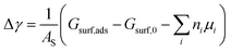 | (1) |
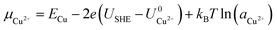
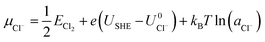
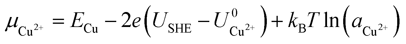
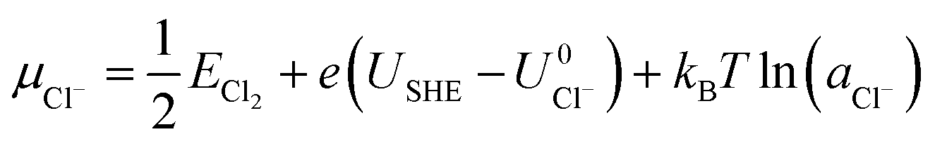
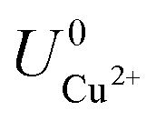
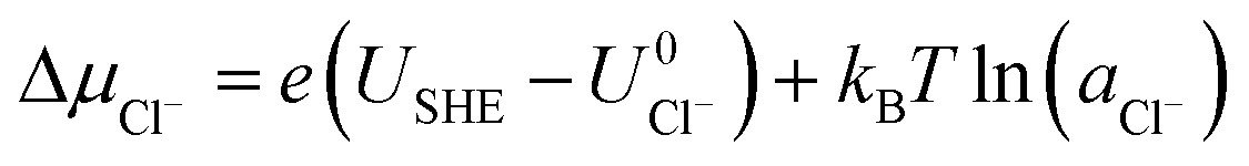
Here, Gsurf,ads and Gsurf,0 are the Gibbs free energies of the ion adsorbed and pristine surfaces, ni is the number of ith ion adsorbed, μi is the electrochemical potential of the ith ion in solution, and AS is the surface area of the calculation cell.28 Since the terms TS and pV are rather small for solids, it is reasonable to neglect these dependencies and equate Gsurf,ads and Gsurf,0 to the total energies obtained from DFT calculations, i.e. Gsurf,ads = Esurf,ads and Gsurf,0 = Esurf,0. To compute the electrochemical potentials of the ions μi, we use the concept of the computational hydrogen electrode generalized to arbitrary ions.29 Under standard conditions, the free energy of a singly charged positive ion plus that of an electron at the Fermi level differs from the free energy of its bulk phase by eU0, where U0 is the standard reduction potential. This relation allows us to obtain μi without having to calculate the solvation energy of ions, but instead derive it from the bulk energy of the material in question. To obtain μi under general thermodynamic conditions, we just correct for the electrode potential with a eUSHE term and the ion concentration with a kBT![[thin space (1/6-em)]](https://www.rsc.org/images/entities/char_2009.gif) ln(a) term, where USHE is the electrode potential relative to the standard hydrogen electrode and a is the ion activity. Thus, we have
ln(a) term, where USHE is the electrode potential relative to the standard hydrogen electrode and a is the ion activity. Thus, we have| |
 | (2) |
| |
 | (3) |
where ECu and ECl2 are the energies of a Cu atom in bulk Cu and Cl2 molecule respectively, both of which are obtained from DFT calculations.  and
and  are the standard reduction potentials and aCu2+ and aCl− are the activities of the Cu2+ and Cl− ions respectively. We can also rewrite eqn (1) in a different way by regrouping the terms,
| | |
Δγ = (Eads − nClΔμCl− − nCuΔμCu2+)/AS
| (4) |
where| | |
Eads = Esurf,ads − Esurf,0 − nClECl2/2 − nCuECu
| (5) |
| |
 | (6) |
| |
 | (7) |
This way, we separate quantities obtained by first-principles calculations from those that are defined by external conditions.
To compute the total energies Esurf,ads and Esurf,0, we perform DFT calculations on atomic slabs with 40.0 Å of vacuum perpendicular to the surface normal. Adsorbates are introduced on both sides of the surface to ensure that the interface dipole is symmetric on both faces. In addition, the electrode potential can be tuned in our simulation by adding or removing electrons to the system, as this becomes surface charge that creates an electric field near the slab which changes the work function. The corresponding electrode bias is then USHE = W − 4.44V, where 4.44V is the standard potential of the hydrogen electrode and W is the work function of the system. We also model the electrolyte solution with an implicit solvent method.30,31 Here, we solve the linearized Poisson–Boltzmann equation in place of the standard Poisson equation to account for screening effects of the ions and solvent. This effectively imposes a dielectric constant that varies from 1.0 in the solute to the bulk value of water in the vacuum region of the calculation. Also, there is an ionic charge term that varies linearly with potential and is parametrized by the Debye length. This addition enables the electric double layer to be represented more realistically and balances any excess surface charge.
Our calculations have been performed using the VASP package32 and the exchange correlation is described using the GGA-PBE density functional.33 Wavefunctions have been expanded using a plane wave basis with an energy cutoff of 500 eV and dispersion interactions are included using the DFT-D2 scheme.34 The ionic potentials are represented using the PAW formalism35 and the Brillouin zone is sampled with the spacing between k-points set to 0.3 Å−1. Geometry was optimized for the neutral system and convergence is reached when each force component is less than 0.01 eV Å−1. Electronic self-consistency is reached when the total energy is converged to within 10−6 eV. The implicit solvent dielectric permittivity is set to the bulk water value of 78.4 and the Debye screening length is determined by the ionic concentration and calculated using eqn (15) of ref. 31.
Results and discussion
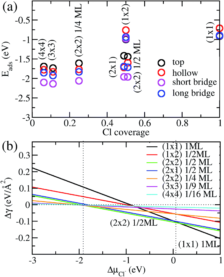
Before we consider Cu2+ and Cl− coadsorption on the Cu (110) surface, let us first look at the simpler case of Cl− adsorption. The starting point of our calculation is the Cu (110) surface, which we construct from a slab of 7 atomic layers thick as shown in Fig. 1a. The slab is oriented such that the (1![[1 with combining macron]](https://www.rsc.org/images/entities/char_0031_0304.gif) 0) and (001) directions are oriented along the x and y axes respectively. The in-plane lattice constants are obtained from DFT calculations on bulk Cu to give 2.57 Å and 3.64 Å for the (1 × 1) surface unit cell. We consider multiple adsorption configurations and adsorption sites for Cl on Cu (110) as shown in Fig. 1b. The structures considered for our calculations are denoted by (1 × 1) 1ML, (1 × 2) 1/2ML, (2 × 1) 1/2ML, (2 × 2) 1/2ML, (2 × 2) 1/4ML, (3 × 3) 1/9ML and (4 × 4) 1/16ML. For each of these structures, we consider Cl adsorbed on the top, long bridge, short bridge and hollow sites, as illustrated in Fig. 1c. We employ neutral slabs in these calculations and solvent effects are included using the implicit model described previously.
0) and (001) directions are oriented along the x and y axes respectively. The in-plane lattice constants are obtained from DFT calculations on bulk Cu to give 2.57 Å and 3.64 Å for the (1 × 1) surface unit cell. We consider multiple adsorption configurations and adsorption sites for Cl on Cu (110) as shown in Fig. 1b. The structures considered for our calculations are denoted by (1 × 1) 1ML, (1 × 2) 1/2ML, (2 × 1) 1/2ML, (2 × 2) 1/2ML, (2 × 2) 1/4ML, (3 × 3) 1/9ML and (4 × 4) 1/16ML. For each of these structures, we consider Cl adsorbed on the top, long bridge, short bridge and hollow sites, as illustrated in Fig. 1c. We employ neutral slabs in these calculations and solvent effects are included using the implicit model described previously.
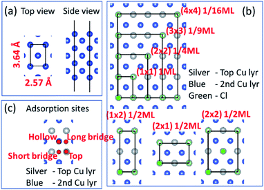 |
| | Fig. 1 (a) Top and side views of the Cu(110) atomistic slab employed in our DFT calculations. (b) Top view of slab illustrating various two-dimensional supercells. Silver and blue atoms represent top and second Cu layers while green represents Cl atoms. (b) Only shows Cl on the top site but calculations also performed for hollow, long bridge and short bridge sites. (c) Hollow, long bridge, short bridge and top adsorption sites illustrated by red dots. | |
We show in Fig. 2a the adsorption energies Eads of Cl on Cu (110). For a given type of adsorption site i.e. top, hollow, long or short bridge, the magnitude of Eads decreases with increasing coverage due to electrostatic repulsion between negatively charged Cl ions.23 At low coverage, the repulsion is weaker due to larger distances between Cl adsorbates and screening by the Cu metal, as a result |Eads| decreases slowly. As the coverage increases, the repulsion energy becomes dominant and this can be seen in the dramatic decrease of |Eads| from 1/2ML to full coverage. At half coverage, we also see stark differences in the adsorption energy between the (1 × 2) 1/2ML, (2 × 1) 1/2ML, (2 × 2) 1/2ML configurations, which we similarly attribute to repulsion between Cl adsorbates. The adsorption energy |Eads| is weakest for the (1 × 2) 1/2ML system while that of (2 × 2) 1/2ML and (2 × 1) 1/2ML configurations are close to each other. This is because the nearest neighbour Cl–Cl distance for the (1 × 2) 1/2ML system is 2.57 Å, which leads to significantly larger electrostatic repulsion than in the (2 × 1) 1/2ML and (2 × 2) 1/2ML configurations, which have the nearest Cl–Cl distances of 3.64 Å and 4.46 Å respectively.
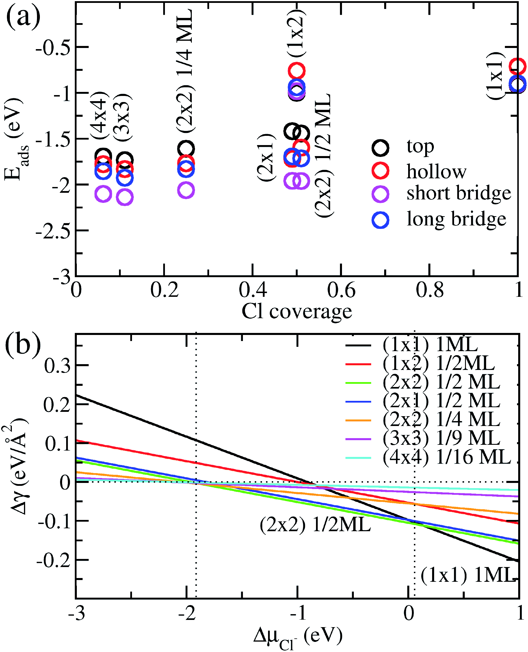 |
| | Fig. 2 (a) Calculated adsorption energy Eads per Cl− ion on Cu(110) as a function of Cl− coverage for different adsorption sites and configurations. (b) Free energy of adsorption Δγ calculated as a function of the electrochemical potential ΔμCl using eqn (4) and Eads obtained above. | |
Another trend that is clear from Fig. 2a is that the short bridge adsorption site is consistently preferred over other sites except for the highest energy configurations (1 × 2) 1/2ML and (1 × 1) 1ML, where the top site is preferred. We believe the preference for the short bridge site is to maximize the binding between Cl and the Cu (110) substrate, as it represents the optimal balance between Cu–Cl distance and number of nearest neighbour Cu–Cl bonds. For example for the (2 × 1) 1/2ML structure, Cl in the short bridge site has two nearest neighbour Cu atoms that are 2.24 Å away, while the top configuration has one nearest neighbour Cu at a distance of 2.11 Å and the hollow site has four nearest neighbour Cu atoms with a Cu–Cl bond length of 2.64 Å. Conversely, for the high coverage configurations (1 × 2) 1/2ML and (1 × 1) 1ML where electrostatic repulsion dominates, the top adsorption site is preferred. This is because the amount of charge transferred is lower owing to reduced interaction between Cl and the Cu substrate. This reduction in electrostatic repulsion more than offsets the lowering in Cu–Cl binding to make the top site the energetically preferred site. In particular, Bader charge analysis shows that the charge transfer to each Cl atom in the (1 × 1) 1ML structure is 0.30e for the short bridge and hollow sites, 0.27e for the long bridge site and 0.24e for the top site. Thus we see that the magnitude of adsorption energy increases with decreasing charge transfer to Cl.
Now that we have determined the energetically preferred Cl adsorption sites for the various configurations, we compute the free energy of adsorption Δγ using eqn (4) for each of these configurations. Specifically, we compute Δγ for the (2 × 1) 1/2ML, (2 × 2) 1/2ML, (2 × 2) 1/4ML, (3 × 3) 1/9ML, (4 × 4) 1/16ML structures with Cl adsorbed on the short bridge site and (1 × 1) 1ML, (1 × 2) 1/2ML configurations with Cl adsorbed on the top site. The effects of the applied electrode bias and ion activity are represented through the electrochemical potential ΔμCl− and Eads is obtained from our previous neutral slab calculations. Also, since the slope of Δγ vs. ΔμCl− is only dependent on the coverage, we only need to consider the lowest adsorption energy site for a given coverage to identify the state with the lowest Δγ. Using this procedure, we generate a plot of Δγ as shown in Fig. 2b, where we identify three stable phases over the range of ΔμCl−. If we focus on the region near ΔμCl− ∼ 0 eV, we have Δγ = Eads/AS and we find that the (1 × 1) 1ML, (2 × 2) 1/2ML and (2 × 1) 1/2ML configurations almost equally stable with the lowest free energies. However as one increases the electrochemical potential ΔμCl−, the (1 × 1) configuration becomes most favourable as the slope −ni/AS, which is the negative of the areal density of Cl adsorbates, is most negative for the (1 × 1) system. For the intermediate region below ΔμCl− ∼ 0 eV, the potential term −niΔμCl/AS in eqn (4) now acts to increase Δγ faster for the (1 × 1) 1ML configuration, and the (2 × 2) 1/2ML and (2 × 1) 1/2ML structures are now the most favourable. This is in agreement with previous LEED work that observed a 0.5 coverage c(2 × 2) Cl adsorption on Cu (110) exposed to HCl.26 However as we keep decreasing the electrochemical potential ΔμCl− to the point beyond ∼−1.9 eV, the potential term becomes large enough to dominate over the adsorption energy and Δγ becomes positive for all the systems considered, hence no adsorption occurs. This is because the energy required to deposit an electron from the ion into the electrode becomes energetically too costly.
In the next step, we look at the coadsorption of Cu2+ and Cl− ions on a Cu (110) surface under different electrode potentials and ion concentrations. In these calculations, we consider Cl− adsorption configurations studied above but limit the coverage to the range 1/4 to 1, as lower coverages were found to be energetically unfavourable. Also, we employ the optimal Cl− adsorption sites found in the preceding section in our coadsorption study. This leads to the calculation geometries of (1 × 1) 1ML and (1 × 2) 1/2ML on the top site and (2 × 1) 1/2ML, (2 × 2) 1/2ML and (2 × 2) 1/4ML configurations on the short bridge site. For Cu2+ adsorption, we consider the same configurations as Cl− adsorption, i.e. (1 × 1) 1ML, (1 × 2) 1/2ML, (2 × 1) 1/2ML, (2 × 2) 1/2ML and (2 × 2) 1/4ML. However, we assume that adsorption occurs on the hollow site, as this is the position that leads to the formation of bulk Cu. The possible configurations for Cu2+ and Cl− adsorption are summarized in Table 1, and we take all possible combinations of the Cu2+ and Cl− configurations to generate 36 co-adsorption systems.
Table 1 Respective adsorption sites for Cl− and Cu2+ ions on Cu(110) considered in our co-adsorption study
| Cl− adsorption sites |
Cu2+ adsorption sites |
| No adsorption |
No adsorption |
| (1 × 1) 1ML top |
(1 × 1) 1ML hollow |
| (1 × 2) 1/2ML top |
(1 × 2) 1/2ML hollow |
| (2 × 1) 1/2ML short bridge |
(2 × 1) 1/2ML hollow |
| (2 × 2) 1/2ML short bridge |
(2 × 2) 1/2ML hollow |
| (2 × 2) 1/4ML short bridge |
(2 × 2) 1/4ML hollow |
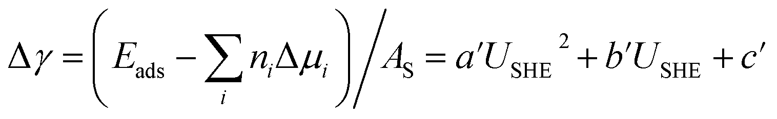
We again apply eqn (4) to compute Δγ for coadsorption, however we introduce between −0.4, −0.2, 0.0, 0.2, 0.4 electrons to the Cu (110) slabs under consideration to obtain Esurf,ads and Esurf,0 for different applied potentials USHE. The potential is evaluated by computing the work function W under different charging conditions and applying the relation USHE = W − 4.44V, giving rise to a potential variation on the order of 1V. The resulting total energies are fit to a quadratic polynomial in USHE so that the total energy can be evaluated at arbitrary USHE. In general, we set
| | |
Esurf,ads = aUSHE2 + bUSHE + c
| (8) |
| | |
Esurf,0 = a0USHE2 + b0USHE + c0
| (9) |
then
eqn (4)–(6) can be combined with
eqn (8) and (9) to give
| |
 | (10) |
where
| | |
b′ = (b − b0 − nCle + 2nCue)/AS
| (11) |
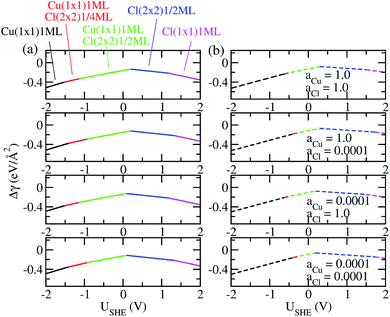
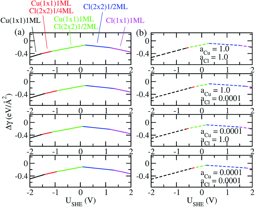
The coefficients a, b, c as well as a0, b0 and c0 are obtained from fits using total energies obtained from charged DFT calculations, and ECu and ECl2 are obtained from separate calculations on bulk fcc Cu and an isolated Cl2 molecule respectively. The coefficients a′, b′ and c′ are computed for each of the 36 co-adsorption configurations and the Δγ are compared at each USHE to identify the phase that minimizes Δγ. This procedure is repeated for the activity combinations (aCl− = 1, aCu2+ = 1), (aCl− = 1, aCu2+ = 0.0001), (aCl− = 0.0001, aCu2+ = 1) and (aCl− = 0.0001, aCu2+ = 0.0001) and the results are plotted in Fig. 3a.
 |
| | Fig. 3 (a) Plot of free energy of adsorption Δγ for most stable phases as function of electrode potential USHE, with Esurf,ads and Esurf,0 obtained using charged calculations. (b) Same as (a) except Esurf,ads and Esurf,0 are obtained from neutral cell calculations. | |
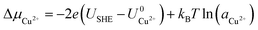
As can be seen, there are five preferred phases over a range of USHE between −2.0 to 2.0 V. Inspection of the plots shows that the nature of the stable configurations and shape of the Δγ plots are mostly independent of the activities aCl and aCu. This is because the term kBTln(a) is much smaller than other energy terms in Δγ at room temperature kBT = 0.025 eV in the studied activity range. We conclude that the activity term only matters if the ion is present in very small concentrations. We list the a′, b′ and c′ values of the 5 stable phases in Table 2. For all the 36 phases considered, we have found that the values of a′ ranges between −0.020 to 0.028 eV Å−2, that of b′ ranges between −0.276 to 0.436e Å−2, and c′ is between −0.326 and −0.001 eV Å−2. Comparing the possible values of a′ and b′, it can be concluded that the quadratic term is generally smaller than the linear term for the range of USHE considered and is therefore not consequential in determining the most stable phase. Near the extremities of the USHE range considered, the most stable phases Cu (1 × 1) 1ML and Cl (1 × 1) 1ML correspond to the systems with the largest magnitudes of b’ for the systems considered, and these large values originate from the large areal densities n/AS arising from the full coverage of adsorbates. Conversely for small values of |USHE|, both quadratic and linear terms fall away and Δγ is dominated by the constant c′ term. The contribution of this term is mostly the adsorption energy Eads plus the reduction potential term 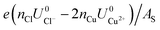 , with
  and
and  . This implies that stable configurations are the ones with low Eads along with the ones with large nCu due to the
 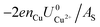 term, which gives rise to the Cl− (2 × 2) 1/2ML configuration owing to its low Eads and Cu (1 × 1) 1ML due to its large nCu.
Table 2 Coefficients of Δγ quadratic fit for the stable coadsorption phases identified for the range |USHE| < 2V
| |
a′ (eV Å−2) |
b′ (e Å−2) |
c′ (eV Å−2) |
| Cu (1 × 1) 1ML |
0.01085 |
0.436 |
−0.117 |
| Cu (1 × 1) 1ML Cl (2 × 2) 1/4ML |
0.00347 |
0.375 |
−0.244 |
| Cu (1 × 1) 1ML Cl (2 × 2) 1/2ML |
−0.00981 |
0.289 |
−0.326 |
| Cl (2 × 2) 1/2ML |
−0.00236 |
−0.164 |
−0.237 |
| Cl (1 × 1) 1ML |
−0.0200 |
−0.276 |
−0.0831 |
As a test of the charging formalism used in this study, we also compute the total energies Esurf,ads and Esurf,0 using neutral slabs for the 36 possible co-adsorption configurations, and generated a USHE independent Eads for computing Δγ. The results of these calculations are seen in Fig. 3b, where we see the same five phases emerging as the most stable, with the shape of the Δγ curve remaining unchanged from the charged calculations. However, the boundaries separating each phase has shifted, and this is particularly pronounced for the boundary between Cu (1 × 1) 1ML and Cu (1 × 1) 1ML + Cl (2 × 2) 1/4ML. From this, it seems that charging the slabs has stabilized Cl− adsorption in the presence of Cu2+ relative to neutral calculations, however the main conclusions between charged and uncharged calculations remain unchanged and there is semi-quantitative agreement between results from these two sets of data.
Finally, we compare the adsorption of only Cl− or Cu2+ ions vs. coadsorption of both Cu2+ and Cl− on Cu (110). To do this, we have calculated the Δγ for the most stable configurations in the presence of Cl− ions only, Cu2+ ions only and both Cl− and Cu2+ ions and plotted them in Fig. 4a, with the activities aCl− and aCu2+ kept at 1.0.
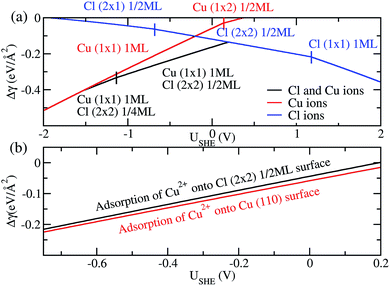 |
| | Fig. 4 (a) Free energy of adsorption Δγ for the most stable phases on Cu (110) in the presence of Cl− ions (blue), Cu2+ ions (red) and both Cu2+ and Cl− ions (black). (b) Free energy of adsorption Δγ for Cu2+ on pristine Cu (110) surface (red) and Cl (2 × 2) 1/2ML surface (black) to form a Cu (1 × 1) 1ML adlayer. | |
For regions where |USHE| is large, the most stable phases consist of adsorption of only a single type of ion. However, in the intermediate region of USHE between −1.4V and 0.2V, the coadsorption of both Cu and Cl ions is energetically preferable. In addition, we can determine if the presence of Cl− promotes the adsorption of Cu2+ on Cu (110). To do this we consider the following reactions Cl (2 × 2) 1/2ML + Cu2+ → Cu (1 × 1) 1ML + Cl (2 × 2) 1/2ML and Cu(110) + Cu2+ → Cu (1 × 1) 1ML. The first reaction is for Cu2+ adsorption on a Cl− covered Cu surface and the second is for Cu2+ on pristine Cu, and we expect these states to be stable in the potential range −0.68V < USHE < 0.15V. The free energy of adsorption for these reactions can be obtained by taking the difference between the black and blue curves of Fig. 4a for the former and the red curve for the latter. As can be seen in Fig. 4b, Δγ is almost identical for adsorption onto either the Cl adsorbed or pristine Cu (110). From this, we can see that the energetics of copper plating is fairly independent of the presence of Cl− ions on the Cu surface, and this strongly suggests that the presence of Cl− neither enhance nor deter the plating of Cu.
Conclusions
In this work, we have studied the adsorption of Cl− as well as coadsorption of Cu2+ and Cl− on the Cu (110) surface using first-principles DFT calculations. The screening arising from the ionic solvent is modeled by solving the linearized Poisson–Boltzmann equation, and the electrode potential is tuned by adding or removing charge to the simulation system. By calculating the free energy of adsorption, we identify the preferred phases of Cl− on Cu(110) as the Cl (1 × 1) 1ML for positive ΔμCl− and Cl (2 × 2) 1/2ML for negative ΔμCl−, while for ΔμCl− < −1.9 V, there are no stable adsorbed phases of Cl−. In addition, we find that for Cl− configurations at low coverage, the short bridge adsorption site is preferred as it maximizes binding between the Cl− adsorbate and Cu substrate, whereas for high coverage configurations where electrostatic repulsion between Cl− is dominant, the top configuration is more favorable as it minimizes charge transfer from Cu to Cl−. For our study of Cu2+ and Cl− coadsorption on Cu (110), we identify five different stable phases over a range of USHE, with the configurations at large |USHE| dominated by full coverage of either Cl− or Cu2+ adsorbates while that of low |USHE| being structures that have large adsorption energies Eads, such as Cl (2 × 2) 1/2ML. In addition, we found that calculating Δγ using neutral slab calculations gives semi-quantitative agreement with charged slab calculations that explicitly model the electrode potential, and that the presence of Cl− does not significantly enhance or deter the plating of Cu2+.
Conflicts of interest
There are no conflicts to declare.
Acknowledgements
This research is supported by the Agency for Science, Technology and Research (A*STAR) under its Defect Science Program. High performance computing facilities were supported by the A*STAR Computational Resource Centre and National Super Computing Centre.
Notes and references
- P. C. Andricacos, C. Uzoh, J. O. Dukovic, J. Horkans and H. Deligianni, IBM J. Res. Dev., 1998, 42, 567 CAS.
- P. M. Vereecken, R. A. Binstead, H. Deligianni and P. C. Andricacos, IBM J. Res. Dev., 2005, 49, 3 CAS.
- T. P. Moffat, D. Wheeler, M. D. Edelstein and D. Josell, IBM J. Res. Dev., 2005, 49, 19 CAS.
- A. C. West, S. Mayer and J. Reid, Electrochem. Solid-State Lett., 2001, 4, C50 CrossRef CAS.
- A. C. West, J. Electrochem. Soc., 2000, 147, 227 CrossRef CAS.
- T. P. Moffat, D. Wheeler, S. K. Kim and D. Josell, J. Electrochem. Soc., 2006, 153, C127 CrossRef CAS.
- T. P. Moffat, D. Wheeler, S. K. Kim and D. Josell, Electrochim. Acta, 2007, 53, 145 CrossRef CAS.
- N. T. M. Hai, K. W. Krämer, A. Fluegel, M. Arnold, D. Mayer and P. Broekmann, Electrochim. Acta, 2012, 83, 367 CrossRef CAS.
- T. M. T. Huynh, F. Weiss, N. T. M. Hai, W. Reckien, T. Bredow, A. Fluegel, M. Arnold, D. Mayer, H. Keller and P. Broekmann, Electrochim. Acta, 2013, 89, 537 CrossRef CAS.
- J. W. Gallaway and A. C. West, J. Electrochem. Soc., 2008, 155, D632 CrossRef CAS.
- J. W. Gallaway, M. J. Willey and A. C. West, J. Electrochem. Soc., 2009, 156, D146 CrossRef CAS.
- J. Mendez, R. Akolkar and U. Landau, J. Electrochem. Soc., 2009, 156, D474 CrossRef CAS.
- T. P. Moffat, D. Wheeler and D. Josell, J. Electrochem. Soc., 2004, 151, C262 CrossRef CAS.
- J. P. Healy, D. Pletcher and M. Goodenough, J. Electroanal. Chem., 1992, 338, 155 CrossRef CAS.
- M. R. H. Hill and G. T. Rogers, J. Electroanal. Chem., 1978, 86, 179 CrossRef CAS.
- Z. V. Feng, X. Li and A. A. Gewirth, J. Phys. Chem. B, 2003, 107, 9415 CrossRef CAS.
- M. Yokoi, S. Konishi and T. Hayashi, Denki Kagaku, 1984, 52, 218 CrossRef CAS.
- P. J. Goddard and R. M. Lambert, Surf. Sci., 1977, 67, 180 CrossRef CAS.
- K. Motai, T. Hashizume, D. R. Jeon, H. Lu, K. Tanaka, H. W. Pickering and T. Sakurai, Jpn. J. Appl. Phys., 1992, 31, L874 CrossRef CAS.
- T. Sakurai and T. Hashizume, Nanotechnology, 1992, 3, 126 CrossRef.
- K. Doll and N. M. Harrison, Chem. Phys. Lett., 2000, 317, 282 CrossRef CAS.
- A. Migani and F. Illas, J. Phys. Chem. B, 2006, 110, 11894 CrossRef CAS PubMed.
- S. Peljhan and A. Kokalj, J. Phys. Chem. C, 2009, 113, 14363 CrossRef CAS.
- D. W. Suggs and A. J. Bard, J. Phys. Chem., 1995, 99, 8349 CrossRef CAS.
- M. R. Vogt, A. Lachenwitzer, O. M. Magnussen and R. J. Behm, Surf. Sci., 1998, 399, 49 CrossRef CAS.
- J. L. Stickney, C. B. Ehlers and B. W. Gregory, Langmuir, 1988, 4, 1368 CrossRef CAS.
- W. H. Li, Y. Wang, J. H. Ye and S. F. Y. Li, J. Phys. Chem. B, 2001, 105, 1829 CrossRef CAS.
- F. Gossenberger, et al., Surf. Sci., 2015, 631, 17 CrossRef CAS.
- J. K. Norskov, J. Rossmeisl, A. Logadottir, L. Lindqvist, J. R. Kitchin, T. Bligaard and H. Jonsson, J. Phys. Chem. B, 2004, 108, 17886 CrossRef CAS.
- K. Mathew, R. Sundararaman, K. Letchworth-Weaver, T. A. Arias and R. G. Hennig, J. Chem. Phys., 2014, 140, 084106 CrossRef PubMed.
- K. Mathew, V. S. Chaitanya Kolluru, S. Mula, S. N. Steinmann and R. G. Hennig, arXiv:1601.03346, 2016.
- G. Kresse and J. Furthmuller, Comput. Mater. Sci., 1996, 6, 15 CrossRef CAS.
- J. P. Perdew, K. Burke and M. Ernzerhof, Phys. Rev. Lett., 1996, 77, 3865 CrossRef CAS PubMed.
- S. Grimme, J. Comput. Chem., 2006, 27, 1787 CrossRef CAS PubMed.
- G. Kresse and D. Joubert, Phys. Rev. B: Condens. Matter Mater. Phys., 1999, 59, 1758 CrossRef CAS.
|
| This journal is © The Royal Society of Chemistry 2020 |
Click here to see how this site uses Cookies. View our privacy policy here. 
 Open Access Article
 This Open Access Article is licensed under a
  ,
Bharathi Madurai Srinivasan,
Ramanarayan Hariharaputran,
Chaitanya Amol Joshi,
David Wu Tai-Yen and
Hongmei Jin*
,
Bharathi Madurai Srinivasan,
Ramanarayan Hariharaputran,
Chaitanya Amol Joshi,
David Wu Tai-Yen and
Hongmei Jin*

 and
and 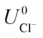 are the standard reduction potentials and aCu2+ and aCl− are the activities of the Cu2+ and Cl− ions respectively. We can also rewrite eqn (1) in a different way by regrouping the terms,
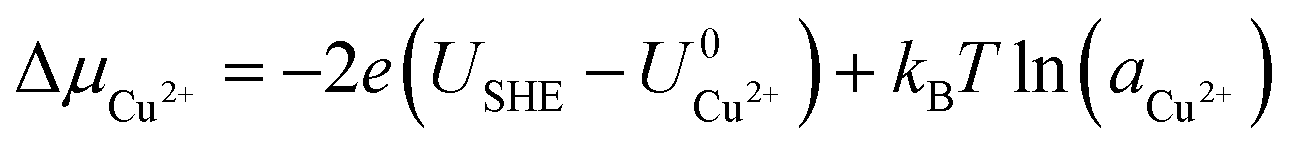


 , with
  and
and  . This implies that stable configurations are the ones with low Eads along with the ones with large nCu due to the
  term, which gives rise to the Cl− (2 × 2) 1/2ML configuration owing to its low Eads and Cu (1 × 1) 1ML due to its large nCu.