 Open Access Article
Creative Commons Attribution 3.0 Unported Licence
Protection of lithium anodes by fibrous silica nanospheres†
Jinxin Fan a,
Yu Luob,
Keliang Jiang
 a and
Cheng Wang
 *a
*a
aInstitute for New Energy Materials & Low-Carbon Technologies, School of Material Science and Engineering, Tianjin University of Technology, Tianjin, 300384, China. E-mail: cwang@tjut.edu.cn
bWeifang Institute for Product Quality Inspection, Weifang, Shandong 261000, China
First published on 20th January 2020
Abstract
Lithium metal (anode) has attracted significant attention for use in lithium-metal batteries due to its high energy density, but its practical application is still hindered by the dendrite growth during the battery charging process. Here, fibrous silica nanospheres were prepared via a direct hydrothermal reaction and coated on a separator to form a composite electrode with lithium sheets. Upon using this composite electrode in a symmetrical cell, the charge and discharge curves became more stable and the overpotential was alleviated compared with that of the bare lithium metal electrode. Meanwhile, the coulombic efficiency obtained from the Li‖Cu cell remained above 95.9% after 200 cycles at 0.5 mA h cm−2. The validity of using this composite electrode in the Li‖LFP (LiFePO4, lithium iron phosphate) cells was also evaluated. The results show that the composite electrode can help restrict the growth of lithium dendrites and the accumulation of dead lithium.
1. Introduction
With the rapid development of portable electronic devices, electric vehicles and renewable energy, high-energy-density batteries are highly demanded.1–7 Currently, the capacity of lithium-ion batteries (LIBs) with the traditional graphite anode has reached its limit and thus, it is highly necessary to search for high-capacity anode materials. Lithium metal is the best choice for the anode in a lithium-metal battery (LMB) because of its considerably high theoretical specific capacity (3860 mA h g−1) and the lowest electrochemical reduction potential (−3.04 V vs. standard hydrogen electrode (SHE)).1,3,8–10 Nevertheless, during the cycling process, due to the uneven distribution of lithium ions on bare lithium metal (Li metal) electrodes, a local high electric field and concentrated lithium ions can accelerate the nucleation and growth of lithium dendrites.11–13 Once lithium dendrites grow to a certain extent, they may pierce the separator and cause safety issues. In addition, the volume change in the lithium anode in the plating/stripping process makes the SEI layer unstable, resulting in the formation of more lithium dendrites, rapid consumption of the electrolyte, and reduction in coulombic efficiency.14In order to solve these problems, scientists have developed the following strategies to stabilize the lithium anode: (1) employing solid electrolytes and modifying liquid electrolytes to improve the stability of the SEI film4,5,15–19 or preparing artificial SEI films via physical, chemical or electrochemical methods.6,20,21 (2) Constructing lithophilic matrices to redistribute lithium ions on the anode surface via chemical binding interactions22–26 or conductive matrices to effectively reduce the formation of dead Li.27–31 (3) Preparing artificial coatings consisting of inorganic (Al2O3 protective layers32–37 and SiO2 nanosphere/nanosheet coating layers on the separator38–41) or organic (thin Nafion layers42) materials. In the case of inorganic SiO2 layers, despite their intrinsic insulating nature, they possess numerous polar groups such as O–H and Si–O22 that can provide sites for the adsorption or/and deposition of lithium ions, which can facilitate the uniform distribution of lithium ions and avoid their accumulation on preformed tips. Furthermore, silica can electrochemically react with Li through solid-state conversion. This will consume freshly formed Li dendrites and hinder their further growth.22,40
In this work, we prepared a simple fibrous silica nanosphere/lithium metal (FSNS/Li) composite electrode for improving the cycling stability of lithium batteries. Fibrous silica nanospheres (FSNSs) were coated on a separator and contacted with lithium sheets via mechanical pressing for the fabrication of the FSNS/Li composite electrode. Compared with solid nanometer silicon coatings, in which solid silicon nanospheres were coated on separators to help suppress the formation of Li dendrites,40,41 our FSNS/Li composite electrode has at least four advantages (Scheme 1): (1) the thickness of the FSNS coating is about 5 μm, and it is thinner than previously reported coatings (∼20 μm).40,41 (2) Fibrous silica nanospheres have a larger specific surface area and can enable more functional groups to participate in the reaction to guide the uniform deposition of lithium ions. (3) The porous structure can provide more space for the deposition of free lithium ions, reducing the deposition of dead lithium on the electrode surface. (4) The pores of the spheres and the gaps among the nanospheres can alleviate the volumetric expansion during the deposition of Li.
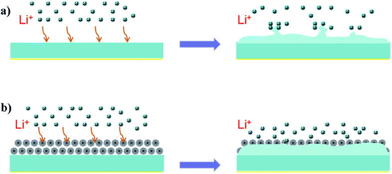 | ||
| Scheme 1 Schematic illustration of Li plating. (a) Li dendrites formed on bare Li-metal electrode and (b) uniform Li deposition on FSNS/Li composite electrode. | ||
2. Experimental section
2.1 Materials
The main materials used to prepare FSNSs are as follows: tetraethyl orthosilicate (TEOS) was purchased from Fuchen (Tianjin) Chemical Reagents Co., Ltd. Pentanol cetylpyridinium bromide and N-methyl-2-pyrrolidone (NMP) were obtained from Shanghai Macklin Bio-Chem Technology Co., Ltd. Cyclohexane, urea and diethyl carbonate (DEC) were purchased from Sinopharm Chemical Reagent Co., Ltd. Copper (Cu) foils and aluminum (Al) foils were purchased from Shenzhen Kejing Star Technology Co., Ltd. Lithium iron phosphate (LiFePO4, LFP) powder was purchased from Tianjin B&M Science and Technology Joint-Stock Co., Ltd. All commercial electrolytes used in this experiment were purchased from Suzhou Duoduo Chemical Technology Co., Ltd.2.2 Preparation of porous silica sphere coating
FSNSs were synthesized via the conventional hydrothermal reaction. The detailed synthesis procedure is reported in ref. 43 and 44. In a typical process, 2.5 g TEOS was dissolved in a mixed solution of 30 mL cyclohexane and 1.5 mL pentanol. Then, 1.0 g cetylpyridinium bromide, 0.6 g urea and 30 mL ultrapure water were added to this solution. The mixture was stirred for 30 min and then transferred to a 100 mL Teflon-lined stainless steel autoclave. The autoclave was sealed and heated in an oven at 120 °C for 4 h. After hydrothermal treatment, the autoclave was allowed to cool to ambient temperature naturally. The precipitate obtained was washed with ultrapure water and absolute ethanol three times and finally calcined at 550 °C for 6 h in air to yield the target porous silica spheres.The FSNS coating was prepared by first blending 0.06 g porous silica spheres and 0.01 g PVDF dispersed in 0.5 mL NMP to form a slurry. Then, the slurry was pasted onto a polypropylene (PP) separator and dried in a vacuum oven at 45 °C for 16 h. After drying, the coated diaphragm was cut into a circle with a diameter of 16 mm.
2.3 Electrochemical measurements
All cells were assembled in an argon-filled glove box with less than 0.1 ppm O2 and 0.1 ppm H2O. The Li‖Li, Li‖Cu and Li‖LiFePO4 cells were assembled in CR2032 coin cells. The cells were tested using a LAND electrochemical testing system (Wuhan LAND Electronics Co., Ltd.) at room temperature.For the galvanostatic cycling test in the symmetrical cells, the capacities of the cells were controlled at 1.0 mA h cm−2 and the cells were cycled at the current densities of 0.5, 1.0 and 2.0 mA cm−2. The cells were assembled using 1.0 M LiPF6 (lithium hexafluorophosphate) in a mixture of EC (ethylene carbonate)/DEC (dimethyl carbonate) (1![[thin space (1/6-em)]](https://www.rsc.org/images/entities/char_2009.gif) :
:![[thin space (1/6-em)]](https://www.rsc.org/images/entities/char_2009.gif) 1 by volume) as the electrolyte and polypropylene (PP) coated with porous silica spheres as the separator.
1 by volume) as the electrolyte and polypropylene (PP) coated with porous silica spheres as the separator.
The Li‖Cu cell was fabricated using a piece of Cu foil as the working electrode for Li metal plating. One M LiTFSI (lithium bis(trifluoromethanesulfonyl)imide) in DOL (1,3-dioxolane)/DME (1,2-dimethoxyethane) (1![[thin space (1/6-em)]](https://www.rsc.org/images/entities/char_2009.gif) :
:![[thin space (1/6-em)]](https://www.rsc.org/images/entities/char_2009.gif) 1 by volume) with 1.0 wt% LiNO3 was added as the electrolyte. The cells were first cycled between 0 V and 0.5 V at 0.05 mA cm−2 for five cycles to stabilize the SEI. Subsequent cycling tests were carried out by depositing 0.5 or 1.0 mA h cm−2 of Li onto the Cu current collector and stripping up to 0.5 V for each cycle.
1 by volume) with 1.0 wt% LiNO3 was added as the electrolyte. The cells were first cycled between 0 V and 0.5 V at 0.05 mA cm−2 for five cycles to stabilize the SEI. Subsequent cycling tests were carried out by depositing 0.5 or 1.0 mA h cm−2 of Li onto the Cu current collector and stripping up to 0.5 V for each cycle.
For fabricating the Li‖LFP cell, the LiFePO4 cathode was prepared by mixing commercial LiFePO4 powder (80 wt%), carbon black (10 wt%) and PVDF (10 wt%) in an NMP solvent to form a slurry. The slurry was coated on an aluminum foil and then dried in a vacuum oven at 80 °C for 12 h. The electrolyte employed was 1.0 M LiPF6 in a mixture of EC (ethylene carbonate), DMC (dimethyl carbonate), and EMC (ethyl methyl carbonate) (volume ratio of 1![[thin space (1/6-em)]](https://www.rsc.org/images/entities/char_2009.gif) :
:![[thin space (1/6-em)]](https://www.rsc.org/images/entities/char_2009.gif) 1
1![[thin space (1/6-em)]](https://www.rsc.org/images/entities/char_2009.gif) :
:![[thin space (1/6-em)]](https://www.rsc.org/images/entities/char_2009.gif) 1). The cells were monitored in the galvanostatic mode within a voltage range of 2.0 and 4.0 V. The galvanostatic cycling test was conducted at 2.0C.
1). The cells were monitored in the galvanostatic mode within a voltage range of 2.0 and 4.0 V. The galvanostatic cycling test was conducted at 2.0C.
2.4 Characterization of materials
The morphologies of the samples were observed via field-emission scanning electron microscopy (SEM, Phenom Desktop SEM operated at 10 kV). The Brunauer Emmett Teller (BET)/Barrett Joyner Halenda (BJH) methods were employed for the determination of specific surface area and pore size distribution using an automated gas adsorption analyzer (Quantachrome). The functional groups in FSNSs were explored via Fourier transform infrared spectrometry (FTIR, PerkinElmer).3. Results and discussion
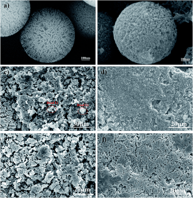
FSNSs were fabricated via a direct and facile hydrothermal reaction. From Fig. S1,† it can be seen that the obtained silica nanospheres have rough surfaces and are about 600 nm in diameter. The zoomed-in image (Fig. 1a) reveals that there are many irregular pores on the surface of the nanospheres, and the pore size varies from several to tens of nanometers. The thickness of the FSNS coating was about 5.0 μm, as revealed by the cross-sectional SEM image (Fig. S2†). The N2 adsorption/desorption isotherm of FSNSs exhibited a typical IV isotherm with an H3 hysteresis loop (Fig. S3(a)†), suggesting the presence of mesopores. The specific surface area (BET) of FSNSs was 351.8 m2 g−1. The pore size (BJH) distribution of FSNSs is illustrated in Fig. S3(b)†, indicating a broad pore size distribution of mainly about 5 nm. This result is consistent with that observed in Fig. 1a. In the FTIR (Fourier transform infrared spectroscopy) spectrum (Fig. S4†), the absorbance peaks at around 1631 (470), 1098, 974 and 803 cm−1 correspond to the Si–OH bending vibration, Si–O–Si asymmetric stretching vibration, Si–O symmetric stretching vibration and O–Si–O asymmetric stretching vibration.To verify the advantages of the porous silica nanosphere-coated separator in a long cycle test, the SEM images of the FSNS/Li composite anode before and after cycling were analyzed and compared with that of the bare Li-metal electrode. The Li‖Cu cells were cycled at a fixed current density of 0.5 mA cm−2 with a stripping/plating capacity of 0.5 mA h cm−2 for each cycle. After 200 cycles, the cells were disassembled in an argon (Ar)-protected glove box. Before SEM analysis, the electrodes were washed with DEC and dried completely. For one FSNS particle, it was observed that the FSNS was wrapped by lithium (Fig. 1a and b). This can be attributed to the adsorption of free lithium ions due to the strong interaction between the Li and O atoms on the surface of FSNSs and enough space for Li deposition within the porous structure during cycling.
At a current density of 0.5 mA cm−2 with a total capacity of 0.5 mA h cm−2, the surface of the bare Li-metal electrode became rough and porous as a result of the uneven deposition of lithium ions (Fig. 1c). Some dendrites and dead lithium (circled in red) were found on the surface of the bare Li-metal electrode (Fig. 1c). In contrast, under the same conditions, the FSNS coating impeded Li ion deposition around the high-current-density position, resulting in a relatively homogeneous lithium ion concentration and expediting the uniform deposition of lithium ions. Furthermore, it can be clearly seen in Fig. 1d that the surface of the FSNS/Li composite electrode is flatter without serious cracking and obvious dendrites. When the capacity was increased to 1.0 mA h cm−2 under the same current density, the composite electrode surface began to crack and a few mossy structures could be observed. Nevertheless, it was still superior to the bare Li-metal electrode (Fig. 1e and f).
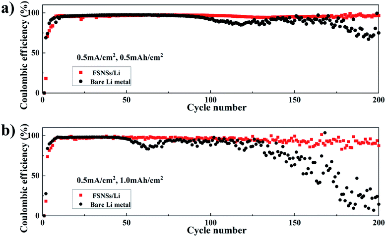
To test the Li coulombic efficiency (CE), which is calculated based on the ratio of the amount of stripped Li to plated Li in each cycle and serves as a critical index to predict the cycle life of lithium-metal batteries (LMBs), Li‖Cu coin cells were fabricated using pieces of Cu foils as the working electrodes for Li metal plating. Fig. 2a and b compare the Li CE of the two Li‖Cu coin cells with and without the FSNS/Li composite electrode. The two cells were cycled with the total capacities of 0.5 and 1.0 mA h cm−2. At a lower capacity, e.g., 0.5 mA h cm−2 (Fig. 2a), the CEs of the two cells were around 97% and comparable for the first 100 cycles. Subsequently, a fluctuation in the CE for the bare Li metal electrode became discernible, indicating the dendrite growth of Li and the formation of dead Li. When the FSNS/Li composite electrode was used, the CE slightly decreased to 95.9% after 200 cycles and the fluctuation was postponed to 170 cycles. Furthermore, upon increasing the capacity to 1.0 mA h cm−2 (Fig. 2b), the cell with the FSNS/Li composite electrode could still maintain higher CE, while the CE of the cell with the bare Li-metal electrode showed rapid decline after 52 cycles. For both cases, it is expected that the fluctuations in CEs should be more severe at higher capacity as a result of the accumulation of dead Li (Fig. 2). Nevertheless, the Li‖Cu cell with the presence of the composite showed improved stability upon electrochemical cycling and a longer service life. This improvement can be again ascribed to the pores and functional groups within FSNSs, which suppress the formation Li dendrites and dead Li. Additionally, the porous structure helps alleviate the volume change during the lithium-ion deposition/dissolution process.
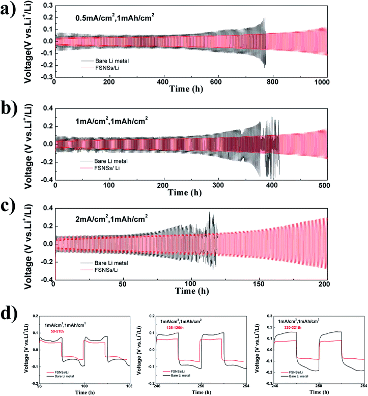
Li‖Li symmetrical cells were assembled for the galvanostatic cycling test. The cells were cycled with a fixed capacity of 1.0 mA h cm−2 at the current densities of 0.5, 1.0, and 2.0 mA cm−2. For the cell using the FSNS/Li composite electrode (Fig. 3a–c), its hysteresis (overpotential between Li deposition and dissolution) increased gradually with the increase in the number of cycles. Under a current density of 0.5 mA cm−2 (Fig. 3a), the symmetric cell delivered a stable voltage curve with a small hysteresis of about 55 mV within 600 h cycling. After 1000 h cycling, the hysteresis was only nearly 3 times the initial hysteresis, which was close to previously reported results.31,45,46 When there were no FSNSs, the cell showed a similar overpotential to that of the cell using FSNSs for the first 107 cycles; then, the hysteresis increased significantly after 121 cycles. After 191 cycles, it reached nearly 200 mV, which was higher than that of the cell using FSNSs. This increase in overpotential originated from the increase in the overall resistance as a result of the formation of dead Li.47 Similar scenarios (Fig. 3b and c) could be observed for the two cells running at higher current densities, e.g., 1.0 mA cm−2 and 2.0 mA cm−2. It should be noted that sudden drops in the hysteresis occurred after 184 (379 h) and 102 (102 h) cycles for cycling at 1.0 and 2.0 mA cm−2, respectively. These phenomena can be attributed to the cell short-circuits caused by piercing the separator31. The advantage of using FSNSs was further supported by the detailed voltage profiles of the cycling plateaus at different cycles. The galvanostatic voltage profiles under different cycles for the two electrodes are compared in Fig. 3d. After the 50th cycle (100 h), the overpotentials were about 70 and 46 mV for the cells assembled without and with FSNSs, respectively. The corresponding profiles became 36 mV (100 mV vs. 64 mV) and 158 mV (250 mV vs. 92 mV) after 125 and 180 cycles.
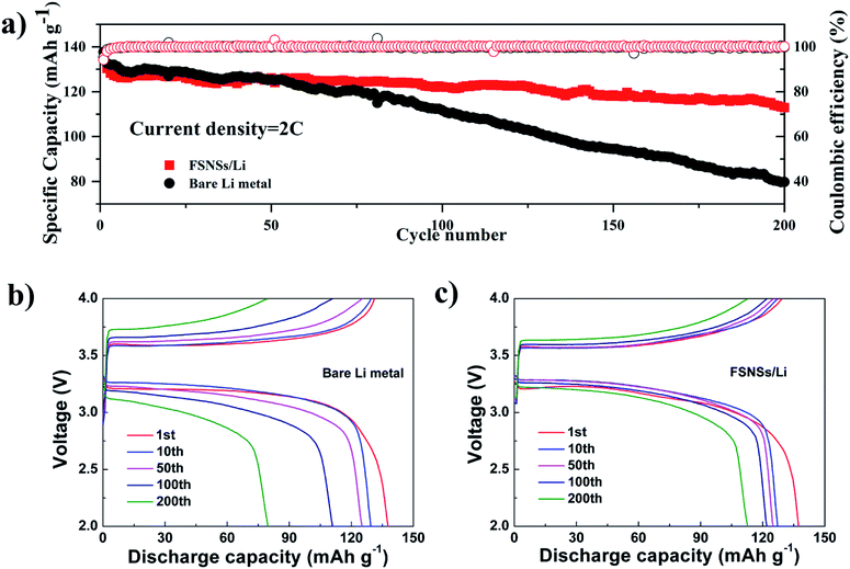
To further assess the application of the FSNS-modified electrode in real lithium-metal batteries, electrodes with and without FSNSs were assembled with an LFP cathode. The long cycling performance of the two cells was investigated under a rate of 2C (Fig. 4a). It was found that the capacity attenuation of the composite electrode was obviously better than that of the unmodified electrode. Fig. 4(b and c) show the specific capacity changes of the two electrodes at the 1st, 50th, 100th and 200th cycle. The first cycle discharge capacities of the two cells were similar and the values were 137.3 mA h g−1 and 137.7 mA h g−1 for the cells with the modified and unmodified Li electrodes, respectively. The capacity decline for the cell without FSNSs was attributed to the deposition of unstable Li ions and increased battery polarization, leading to a low capacity of 79.7 mA h g−1 (about 58% capacity retention) after 200 cycles. In contrast, the cell with the modified electrode delivered higher specific capacity (122.1 mA h g−1) and capacity retention (89%) for the initial 100 cycles, which degraded gradually to 112.7 mA h g−1 (82% capacity retention) after 200 cycles.
4. Conclusions
In summary, we reported a simple method for improving the cycling stability via forming FSNS/Li composite electrodes. The porous structure of FSNSs provided enough place for free lithium ion redeposition to inhibit the growth of lithium dendrites and the accumulation of dead lithium. As a result, the overpotential of the symmetrical battery with the FSNS/Li composite electrode could be improved in comparison to that of the bare Li-metal electrode at different current densities. The FSNS/Li composite electrode exhibited a high coulombic efficiency of 97% for the first 96 cycles, which was still maintained at 95% after 200 cycles at 0.5 mA cm−2. The galvanostatically cycling test on the Li‖LFP cells showed that the FSNS/Li composite electrode has excellent stability in the charging and discharging cycles. This FSNS/Li composite electrode provides a new method for limiting the growth of lithium dendrites and the formation of dead lithium.Conflicts of interest
There are no conflicts to declare.Acknowledgements
This work was financially supported by National Key R&D Program of China (2017YFA0700104), NSFC (21571170 and 21501168) and Tianjin Municipal Science and Technology Commission (17JCZDJC000).References
- X. B. Cheng, R. Zhang, C. Z. Zhao and Q. Zhang, Chem. Rev., 2017, 117, 10403–10473 CrossRef CAS PubMed.
- X. B. Cheng, R. Zhang, C. Z. Zhao, F. Wei, J. G. Zhang and Q. Zhang, Adv. Sci., 2016, 3, 1500213 CrossRef PubMed.
- W. Jia, C. Fan, L. Wang, Q. Wang, M. Zhao, A. Zhou and J. Li, ACS Appl. Mater. Interfaces, 2016, 8, 15399–15405 CrossRef CAS PubMed.
- X. Q. Zhang, X. Chen, X. B. Cheng, B. Q. Li, X. Shen, C. Yan, J. Q. Huang and Q. Zhang, Angew. Chem., Int. Ed., 2018, 57, 5301–5305 CrossRef CAS PubMed.
- S. Li, H. Dai, Y. Li, C. Lai, J. Wang, F. Huo and C. Wang, Energy Storage Mater., 2019, 18, 222–228 CrossRef.
- D. Lin, Y. Liu, W. Chen, G. Zhou, K. Liu, B. Dunn and Y. Cui, Nano Lett., 2017, 17, 3731–3737 CrossRef CAS PubMed.
- C. Yan, X. B. Cheng, Y. Tian, X. Chen, X. Q. Zhang, W. J. Li, J. Q. Huang and Q. Zhang, Adv. Mater., 2018, 30, 1707629 CrossRef PubMed.
- D. Lin, Y. Liu and Y. Cui, Nat. Nanotechnol., 2017, 12, 194–206 CrossRef CAS PubMed.
- W. Xu, J. Wang, F. Ding, X. Chen, E. Nasybulin, Y. Zhang and J. G. Zhang, Energy Environ. Sci., 2014, 7, 513–537 RSC.
- K. Liu, A. Pei, H. R. Lee, B. Kong, N. Liu, D. Lin, Y. Liu, C. Liu, P. C. Hsu, Z. Bao and Y. Cui, J. Am. Chem. Soc., 2017, 139, 4815–4820 CrossRef CAS PubMed.
- D. Koo, S. Ha, D. M. Kim and K. T. Lee, Curr. Opin. Electrochem., 2017, 6, 70–76 CrossRef CAS.
- X. Y. Yue, X. L. Li, J. Bao, Q. Q. Qiu, T. C. Liu, D. Chen, S. S. Yuan, X. J. Wu, J. Lu and Y. N. Zhou, Adv. Energy Mater., 2019, 9, 1901491 CrossRef.
- X. Y. Yue, X. L. Li, W. W. Wang, D. Chen, Q. Q. Qiu, Q. C. Wang, X. J. Wu, Z. W. Fu, Z. Shadike, X. Q. Yang and Y. N. Zhou, Nano Energy, 2019, 60, 257–266 CrossRef CAS.
- B. D. Adams, J. Zheng, X. Ren, W. Xu and J. G. Zhang, Adv. Energy Mater., 2018, 8, 1702097 CrossRef.
- Z. Fang, Q. Ma, P. Liu, J. Ma, Y. S. Hu, Z. Zhou, H. Li, X. Huang and L. Chen, ACS Appl. Mater. Interfaces, 2017, 9, 4282–4289 CrossRef CAS PubMed.
- Y. Li, Z. Yang, Z. Wu, J. Li, J. Zou, C. Jiang, J. Yang, L. Wang and X. Niu, Solid State Ionics, 2018, 324, 144–149 CrossRef CAS.
- Y. Ouyang, Y. Guo, D. Li, Y. Wei, T. Zhai and H. Li, ACS Appl. Mater. Interfaces, 2019, 11, 11360–11368 CrossRef CAS PubMed.
- X. Ren, L. Zou, S. Jiao, D. Mei, M. H. Engelhard, Q. Li, H. Lee, C. Niu, B. D. Adams, C. Wang, J. Liu, J. G. Zhang and W. Xu, ACS Energy Lett., 2019, 4, 896–902 CrossRef CAS.
- Y. Yang, J. Xiong, S. Lai, R. Zhou, M. Zhao, H. Geng, Y. Zhang, Y. Fang, C. Li and J. Zhao, ACS Appl. Mater. Interfaces, 2019, 11, 6118–6125 CrossRef CAS PubMed.
- J. J. Xu, Q. C. Liu, Y. Yu, J. Wang, J. M. Yan and X. B. Zhang, Adv. Mater., 2017, 29, 1606552 CrossRef PubMed.
- W. Wang, X. Yue, J. Meng, J. Wang, X. Wang, H. Chen, D. Shi, J. Fu, Y. Zhou, J. Chen and Z. Fu, Energy Storage Mater., 2019, 18, 414–422 CrossRef.
- X. B. Cheng, T. Z. Hou, R. Zhang, H. J. Peng, C. Z. Zhao, J. Q. Huang and Q. Zhang, Adv. Mater., 2016, 28, 2888–2895 CrossRef CAS PubMed.
- Z. Liang, G. Zheng, C. Liu, N. Liu, W. Li, K. Yan, H. Yao, P. C. Hsu, S. Chu and Y. Cui, Nano Lett., 2015, 15, 2910–2916 CrossRef CAS PubMed.
- N. Li, W. Wei, K. Xie, J. Tan, L. Zhang, X. Luo, K. Yuan, Q. Song, H. Li, C. Shen, E. M. Ryan, L. Liu and B. Wei, Nano Lett., 2018, 18, 2067–2073 CrossRef CAS PubMed.
- S. Liu, X. Xia, Y. Zhong, S. Deng, Z. Yao, L. Zhang, X. B. Cheng, X. Wang, Q. Zhang and J. Tu, Adv. Energy Mater., 2018, 8, 1702322 CrossRef.
- H. Zhang, X. Liao, Y. Guan, Y. Xiang, M. Li, W. Zhang, X. Zhu, H. Ming, L. Lu, J. Qiu, Y. Huang, G. Cao, Y. Yang, L. Mai, Y. Zhao and H. Zhang, Nat. Commun., 2018, 9, 3729 CrossRef PubMed.
- D. Li, X. Zhou, X. Guo, B. Yuan, Y. Liu, C. M. Ortega, L. Sun and Z. Liu, J. Alloys Compd., 2016, 657, 109–114 CrossRef CAS.
- X. Cao, Y. Shi, W. Shi, G. Lu, X. Huang, Q. Yan, Q. Zhang and H. Zhang, Small, 2011, 7, 3163–3168 CrossRef CAS PubMed.
- L. L. Lu, J. Ge, J. N. Yang, S. M. Chen, H. B. Yao, F. Zhou and S. H. Yu, Nano Lett., 2016, 16, 4431–4437 CrossRef CAS PubMed.
- Q. Yun, Y. B. He, W. Lv, Y. Zhao, B. Li, F. Kang and Q. H. Yang, Adv. Mater., 2016, 28, 6932–6939 CrossRef CAS PubMed.
- Q. Li, S. Zhu and Y. Lu, Adv. Funct. Mater., 2017, 27, 1606422 CrossRef.
- E. Kazyak, K. N. Wood and N. P. Dasgupta, Chem. Mater., 2015, 27, 6457–6462 CrossRef CAS.
- Y. Zhao, L. V. Goncharova, A. Lushington, Q. Sun, H. Yadegari, B. Wang, W. Xiao, R. Li and X. Sun, Adv. Mater., 2017, 29, 1606663 CrossRef PubMed.
- H. K. Jing, L. L. Kong, S. Liu, G. R. Li and X. P. Gao, J. Mater. Chem. A, 2015, 3, 12213–12219 RSC.
- Z. Peng, S. Wang, J. Zhou, Y. Jin, Y. Liu, Y. Qin, C. Shen, W. Han and D. Wang, J. Mater. Chem. A, 2016, 4, 2427–2432 RSC.
- L. Chen, J. G. Connell, A. Nie, Z. Huang, K. R. Zavadil, K. C. Klavetter, Y. Yuan, S. Sharifi Asl, R. Shahbazian Yassar and J. A. Libera, J. Mater. Chem. A, 2017, 5, 12297–12309 RSC.
- A. C. Kozen, C. F. Lin, A. J. Pearse, M. A. Schroeder, X. Han, L. Hu, S. B. Lee, G. W. Rubloff and M. Noked, ACS Nano, 2015, 9, 5884–5892 CrossRef CAS PubMed.
- J. H. Park, J. H. Cho, W. Park, D. Ryoo, S. J. Yoon, J. H. Kim, Y. U. Jeong and S. Y. Lee, J. Power Sources, 2010, 195, 8306–8310 CrossRef CAS.
- W. K. Shin and D. W. Kim, J. Power Sources, 2013, 226, 54–60 CrossRef CAS.
- K. Liu, D. Zhuo, H. W. Lee, W. Liu, D. Lin, Y. Lu and Y. Cui, Adv. Mater., 2017, 29, 1603987 CrossRef PubMed.
- P. J. Kim, K. Kim and V. G. Pol, Electrochim. Acta, 2018, 283, 517–527 CrossRef CAS.
- J. Song, H. Lee, M. J. Choo, J. K. Park and H. T. Kim, Sci. Rep., 2015, 5, 14458 CrossRef CAS PubMed.
- V. Polshettiwar, D. Cha, X. Zhang and J. M. Basset, Angew. Chem., Int. Ed., 2010, 49, 9652–9656 CrossRef CAS PubMed.
- X. P. Ding, Y. B. Wang and Y. D. Huang, J. Harbin Inst. Technol., 2018, 50, 116–121 Search PubMed.
- S. H. Wang, Y. X. Yin, T. T. Zuo, W. Dong, J. Y. Li, J. L. Shi, C. H. Zhang, N. W. Li, C. J. Li and Y. G. Guo, Adv. Mater., 2017, 29, 1703729 CrossRef PubMed.
- Y. J. Zhang, S. F. Liu, X. L. Wang, Y. Zhong, X. H. Xia, J. B. Wu and J. P. Tu, J. Power Sources, 2018, 374, 205–210 CrossRef CAS.
- H. Liu, E. Wang, Q. Zhang, Y. Ren, X. Guo, L. Wang, G. Li and H. Yu, Energy Storage Mater., 2019, 17, 253–259 CrossRef.
Footnote |
| † Electronic supplementary information (ESI) available. See DOI: 10.1039/c9ra09481d |
| This journal is © The Royal Society of Chemistry 2020 |

