
 Open Access Article
 This Open Access Article is licensed under a Creative Commons Attribution-Non Commercial 3.0 Unported Licence
Treatment of crude oil contaminated wastewater via an electrochemical reaction†
Khanindra Sharmaa,
Suravi Kalitaa,
Neelotpal Sen Sarmab and
Arundhuti Devi *a
*a
aEnvironmental Chemistry Laboratory, Resource Management and Environment Section, Life Sciences Division, Institute of Advanced Study in Science and Technology, Guwahati 781035, Assam, India. E-mail: deviarundh2@yahoo.co.in; Fax: +91-361-2273062
bAdvanced Materials Laboratory, Physical Sciences Division, Institute of Advanced Study in Science and Technology, Guwahati 781035, Assam, India
First published on 9th January 2020
Abstract
A cost-effective and catalyst-free approach for the treatment of oil field formation water has been extensively explored in this work. ZnO NPs were synthesized via an electrochemical reaction using hydrogen peroxide as the electrolyte. The XRD and TEM analysis depicted the high purity and wurtzite hexagonal structure of ZnO NPs with an average size of 35 ± 5 nm. TGA data showed the thermal stability of the synthesized material up to 750 °C. The efficiency of the removal of hydrocarbons from formation water by the combination of electrochemical reaction and synthesized ZnO NPs was monitored by GC-MS and FTIR. GC-MS analysis revealed that out of 214 compounds (present in the untreated sample), a total of 131 compounds were adsorbed by ZnO NPs. Further, the absence of any compound in the chromatogram of the treated sample attests that the rest of the compounds were completely or partially degraded by electrochemical degradation reaction. Moreover, this technique overcomes some of the important drawbacks of the existing techniques in the area of electrochemical research, such as the generation of toxic byproducts, unwanted side reactions, and involvement of hazardous chemicals.
1. Introduction
Oil field formation water is the wastewater produced during the crude oil drilling process and one of the most significant volume waste streams produced as a result of oil exploration practice.1 The total volume of formation water generated during the oil drilling process is about 1.6 times that of the amount of crude oil produced.2,3 Formation water contains a wide range of cyclic and acyclic hydrocarbons in addition to several other toxic compounds.4 The presence of such lethal compounds makes it highly carcinogenic, and it targets the essential organs that incorporate the liver, kidney, and thyroid gland tissue, causing total organ damage. Moreover, the presence of cyclic and aromatic hydrocarbons cause severe damage to the glucose metabolism cycle of a living being.5 Subsequently, designing practical methods for the treatment of formation water is crucial and thus raises a call for an immediate response.6,7 Various treatment measurements have already been reported for the treatment of formation water, which include adsorption, coagulation, bacterial degradation, and chemical degradation via oxidation.8,9 However, electrochemical and adsorption measurements are the best strategies among all other accessible methods due to their effortlessness and high proficiency.10,11 In the last couple of years, much importance had been given to the electrochemical method as a treatment technique for the remediation of wastewater because of its eco-friendliness and compatibility over other treatment strategies.12,13 The principal mechanism of treatment of debased water by electrochemical response includes oxidation and reduction by the electrodes alongside additional oxidation by various radicals and ions formed during the entire chemical process.14 However, the in situ electro-generation of free radicals gives the electrochemical reactions an advantage over other degradation reactions.10Moreover, the electrochemical reaction involves less of reagents, chiefly driven by electric flow, and is responsible for the production of radicals in the electrodes, primarily on the cathode.13–15 Additionally, utilization of hydrogen peroxide as an electrolyte in electrochemical reaction adds another measurement to the remediation arrangement as it is considered as a green concoction, and there is no side-effect left toward the end of the response.16,17 This adds a remarkable advantage to the aforementioned technique for a field trial. One of the major disadvantages of electrochemical treatment is cost ineffectiveness and demands a huge amount of money to operate.18 With this view in mind, this study was carried out to develop a novel, cost-effective electrochemical process with Zn rods as electrodes (both as anode and cathode). The present study was also designed to synthesize ZnO nanoparticles (NPs) for the effective removal of petroleum hydrocarbons from formation water via adsorption mechanism owing to the high efficiency and benefits of nanoparticles as adsorbent due to its high surface area.19
2. Materials and methods
2.1 Experimental section
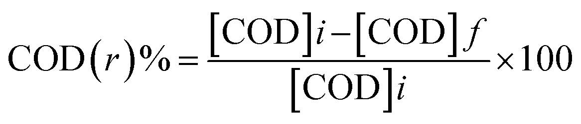
Two Zn electrodes, each of length 14 cm and diameter 0.9 cm, were dipped in 200 ml of formation water sample under constant stirring. The voltage was optimized by carrying out the experiment at 9, 12, and 15 volts of electric current using a regulated multiple power supply (model: Scientech 4077) (Fig. 1). An optimized amount of 4 ml hydrogen peroxide (30% analytical grade) was added to the reaction mixture, which plays the role of both electrolyte and oxidizing agents. The degradation of hydrocarbons during the progress of the electrochemical reaction was monitored by measuring the chemical oxygen demand (COD) value of the samples at different time intervals. COD of untreated and treated samples were investigated as per APHA.20here, [COD]i is the initial COD of the sample, and [COD]f is the final COD with respect to a specific time and sample type.
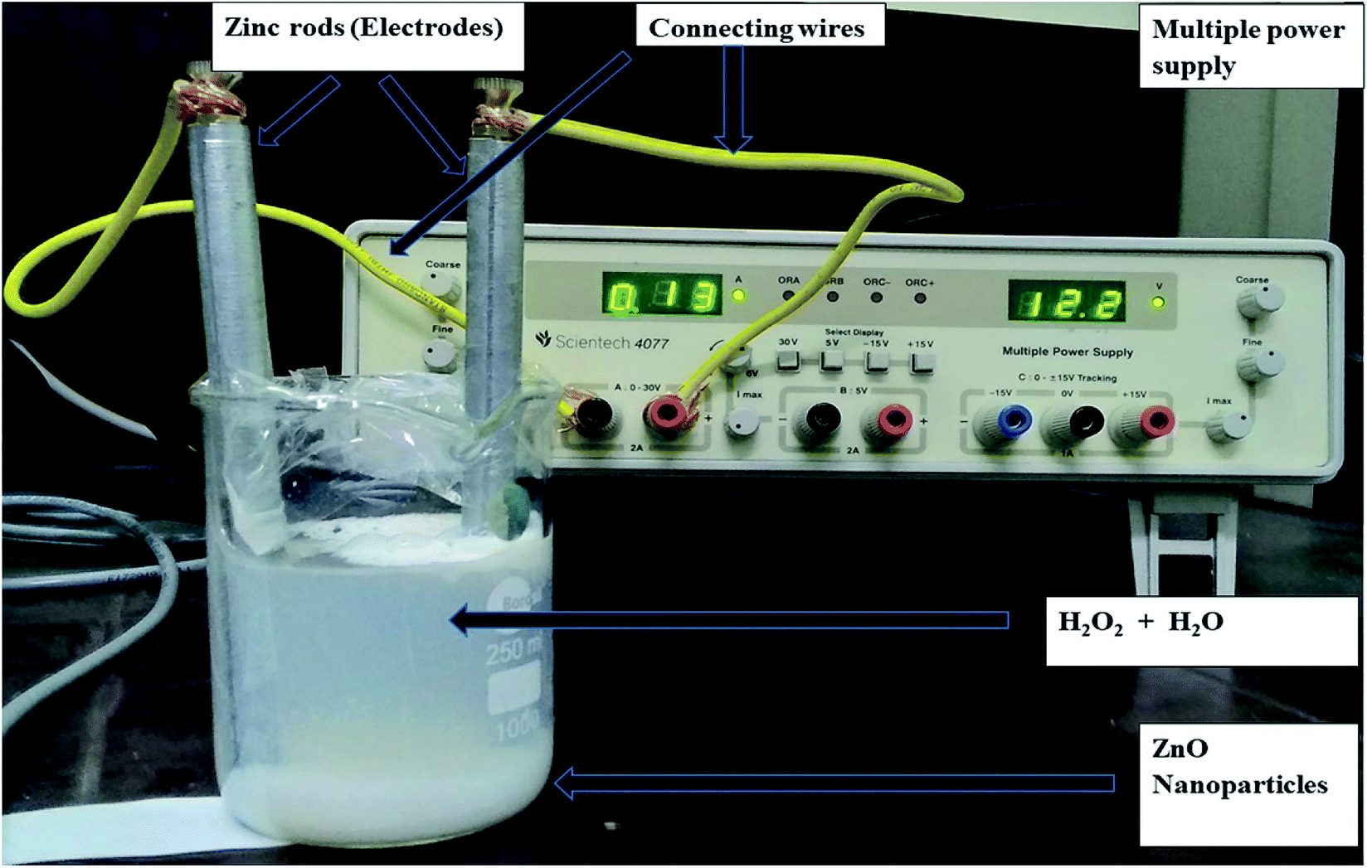 | ||
| Fig. 1 Schematic diagram of the experimental set-up (clean water is used to make the ZnO nanoparticles more visible). | ||
After completion of the electrochemical reaction, ZnO NPs settled at the bottom of the reacting vessel were stirred (at 1200 rpm) to ensure complete adsorption of the remaining non-degraded and partially degraded hydrocarbons from the formation water sample. Finally, ZnO NPs were separated through centrifugation at 10![[thin space (1/6-em)]](https://www.rsc.org/images/entities/char_2009.gif) 000 rpm and analyzed with Gas Chromatographic-Mass Spectroscopy (GC-MS) for hydrocarbon content.
000 rpm and analyzed with Gas Chromatographic-Mass Spectroscopy (GC-MS) for hydrocarbon content.
2.2 Characterization of ZnO NPs and formation water
The formation water sample was collected from Group Gathering Station (GGS) of Oil and Natural Gas Corporation (ONGC), Borhola, Assam, India, and stored in a dark, dry place. The synthesis of ZnO NPs was confirmed by UV-DRS spectra (UV-2600 Shimadzu spectrophotometer) with BaSO4 as the reference and X-ray diffraction (XRD) patterns using powder diffractometer (Bruker D8 Advanced). Further, the surface morphology of the synthesized ZnO NPs was characterized using a Carl Zeiss (P-Sigma, Germany) Scanning Electron Microscope and transmission electron microscopy (TEM) (model: JEM 2100). The particle size of the ZnO NPs was estimated using Malvern Zeta sizer Nano series (Nano-ZS90). Brunauer–Emmett–Teller (BET) (Quantachrome Autosorb-IQ MP) analysis was carried out to investigate the surface area and pore size of ZnO NPs where the samples were degassed at 150 °C for 3 hours under nitrogen atmosphere. The thermal stability of ZnO NPs was measured using PerkinElmer, TGA 4000 instrument before and after adsorption of hydrocarbons.The identification of the hydrocarbons present in the formation water sample was done using a Gas Chromatograph-Mass Spectrometer (GC/MSTQ8030, Shimadzu, Japan) with an auto-injector (AOC 20I, GC-2010, E). For GC-MS analysis, the samples were extracted with Dichloromethane (DCM). All the analyses were carried out with a split ratio of 20:1, and helium was used as carrier gas with a flow rate of 1.0 mL min−1. The column used in the system was EB-5MS, and the injection temperature was set at 300 °C. The column oven temperature was set at 60 °C with a hold time of 5 min and was subsequently increased to 300 °C with a ramp of 10 °C/min. The final hold was for 31 min. The ion source temperature was set at 230 °C for MS using an interface temperature of 310 °C. The mass range (m/z) was selected as 45–800 for the entire analysis. The chromatograms were analyzed using GC-MS post-run software. The chromatogram peaks were integrated by considering the slope of 13000. In addition to ZnO NPs, the Fourier-transform infrared (FT-IR) (NICOLET 6700 FTIR-Spectrometer) spectra were also recorded for the untreated and treated formation water samples.
3. Results and discussion
3.1 Initial characterization of formation water
Initial characterization of the sample was done by determining a few important physicochemical parameters, which were then compared with the prescribed permissible limits of the World Health Organisation (WHO)21 for industrial effluents in Table 1. Though the parameters total dissolved solids (140.2 ± 14.3 mg L−1), and pH (8.3 ± 0.4) were within WHO permissible limits of 450 mg L−1 and 6.5–8.5. However, most of the parameters such as total solids (5573 ± 25.5 mg L−1), total suspended solids (5532.8 ± 30.7 mg L−1), turbidity (50 ± 8.52 NTU), conductivity (4.19 ± 0.73 mS cm−1), total petroleum hydrocarbon (TPH) (2566 ± 48.54 mg L−1) and Chemical Oxygen Demand (COD) (3118 ± 35 mg L−1) content were found to be above the permissible limits of WHO (650 mg L−1, 200 mg L−1, 5–10 NTU, 1 × 10⁻³ mS cm−1 and 300 mg L−1, respectively). Hence, the treatment of oil field formation water is necessary to reduce the ground and surface water contamination by petroleum hydrocarbons.| Wastewater | Experimental condition | Treatment efficiency | Reference |
|---|---|---|---|
| Textile wastewater containing basic red 46 dye | Use of ZnO NPs ZnO nanoparticles for enhancing the sonocatalytic decolorization of basic red 46 (BR46) in the aqueous phase | Up to 89.92% decolorization | 50 |
| pH and temperature optimization is required | |||
| Wastewater containing acid red 17 dye | Undoped and Pr-doped ZnO NPs were used for the degradation of acid red 17 under ultrasonic irradiation | Decolorization efficiency upto 100% | 51 |
| Temperature optimization is required | |||
| Wastewater containing permethrin solution | Adsorption (mechanical stirrer) using chitosan-ZnO NPs | 99% (deals with pesticide) | 52 |
| pH optimization is not required | |||
| Industrial wastewater | Mg and ZnO NPs were prepared for the removal of copper from industrial wastewater (adsorption mechanism) | 92–98% (deals with only copper) | 53 |
| pH and temperature optimization is required | |||
| Pharmaceutical industry wastewater | Photocatalytic decomposition of tetracycline and ibuprofen was carried out under batch conditions. The reactor was placed into an aluminum box, stirred and irradiated from the top with four UV-Vis solarium lamps | Near 80% | 54 |
| pH and temperature optimization is required | |||
| Fast green and Victoria blue contaminated wastewater | Ni–ZnO NPs have been prepared by a precursor-based route via chemical precipitation method by using surfactant CTAB at low temperature | More than 90% | 55 |
| pH optimization is required | |||
| Formation water | Electrochemical degradation was followed by the adsorption (using ZnO NPs) | ∼91% | This work |
| pH and temperature optimization is not required |
3.2 Electrochemical reaction and its mechanism
The formation water samples were subjected to the electrochemical treatment with Zn rods as electrodes and H2O2 as the electrolyte, and during the progress of the electrochemical reaction, the ZnO NPs were formed in the in situ condition. On completion of the reaction, the samples, along with ZnO NPs, were subjected to magnetic stirring at around 1200 rpm, which resulted in the adsorption of previously partially degraded or non-degraded hydrocarbons. Finally, the samples were put in centrifugation at 10000 rpm for 40 minutes to separate the ZnO NPs from the treated sample.
The effect of the parameters such as hydrogen peroxide and voltage on the electrochemical reaction was also analyzed.
| H2O2 +e− → OH− +OH˙ | (1) |
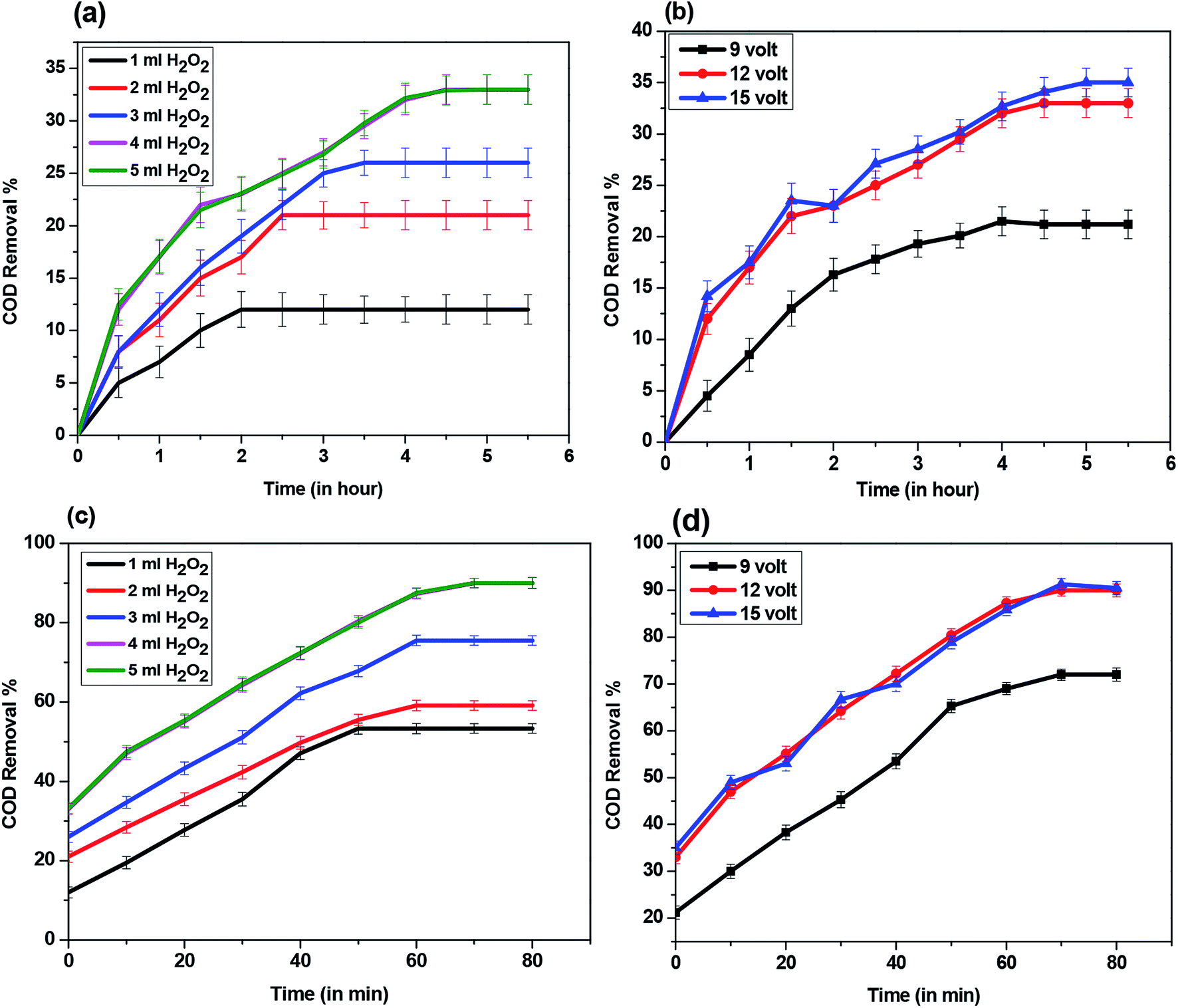 | ||
| Fig. 2 COD removal % by (a) electrochemical reaction at 12 volts and different concentration of H2O2 in mL, (b) electrochemical reactions operated at different applied voltage (9, 12, 15 volts) (c) ZnO NPs formed by different dose of H2O2 with power supply of 12 volts, and, (d) ZnO nanoparticles formed at different applied voltage (9, 12, 15 volts). | ||
Hydroxyl radicals further react with hydrocarbons to yield lower hydrocarbons, which are non-toxic in nature. The probable reaction via which degradation of hydrocarbon took place is given below.22
| R–H + ˙OH → R˙ + HOH | (2) |
3.3 Characterization of synthesized ZnO NPs
The probable reaction which leads to the formation of ZnO NPs during the electrochemical process is shown by eqn (3): 23| Zn2+ + H2O2 + 2e− → ZnO + H2O | (3) |
The synthesized ZnO NPs were then characterized for surface morphology, particle and pore size, thermal stability. The synthesis of ZnO NPs was confirmed by UV-DRS absorption spectra as the obtained peaks at ∼370 nm (Fig. 3(A-a)) lied within the previously established absorbance peaks for ZnO ranging between 355-380 nm.24–26 Even after the adsorption of hydrocarbons by ZnO NPs, a large shift (∼355 nm) in the peaks was not observed (Fig. 3(A-b)). This indicates that the synthesized material (ZnO NPs) does not undergo any kind of chemical change even after the adsorption of hydrocarbons. This has been further confirmed by the study of the crystal structure of ZnO NPs using XRD analysis. On comparing the XRD diffraction patterns of synthesized ZnO NPs before and after adsorption of hydrocarbons with that of XRD pattern of commercial (analytical grade) ZnO, it was found that synthesized ZnO NPs (Fig. 3(B-b)) and commercial ZnO (Fig. 3(B-a)) were characterized by distinct diffraction peaks at 31.7°, 34.3°, 36.2°, 47.5°, 56.5° and 62.8° associated to the (100), (002), (101), (102), (110), (103) crystal planes (Fig. 3B).27 Moreover, JCPDS No. 01-089-1397 and 03-065-3411 corresponding to the ZnO NPs before and after adsorption indicates that the synthesized ZnO is having hexagonal wurtzite. The peak intensity is sharp, and no extra peaks corresponding to other elements were detected which indicates the purity of the material.28,29
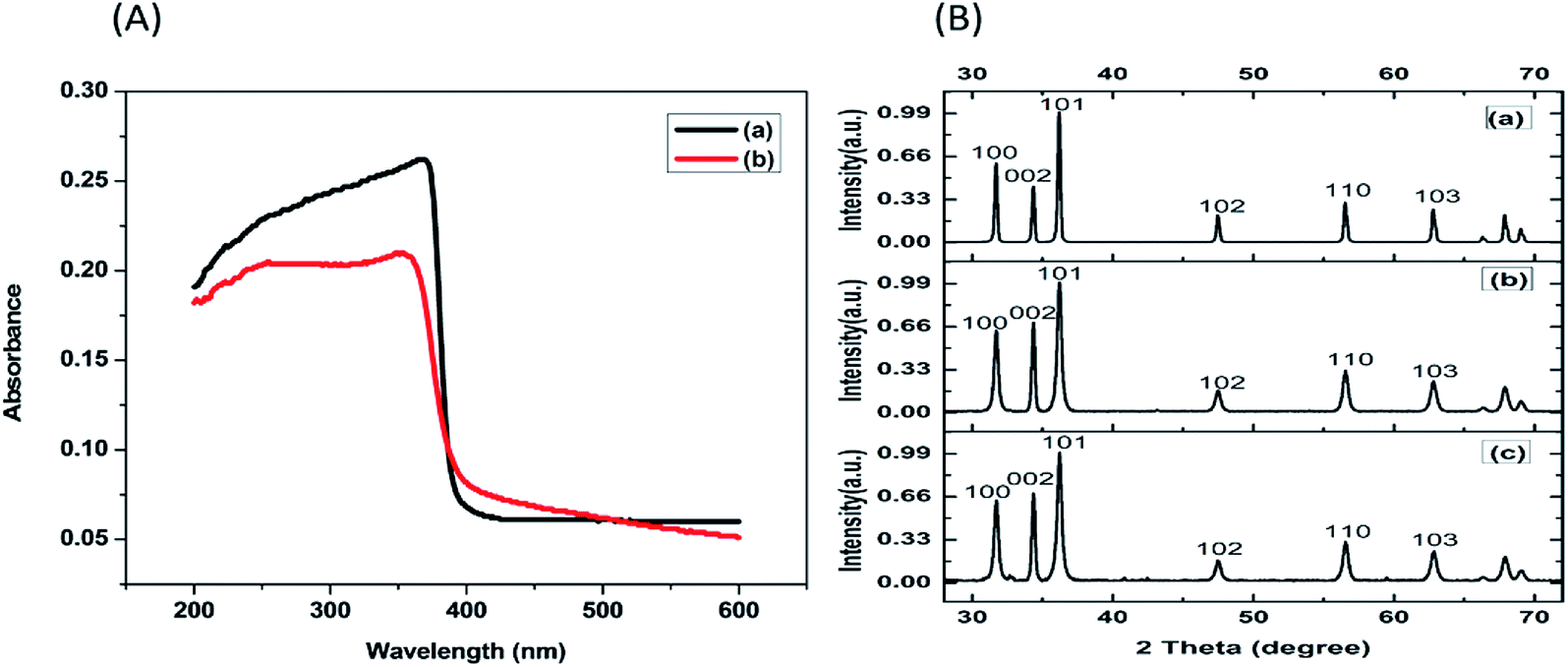 | ||
| Fig. 3 (A) UV-DRS absorption spectrum of (a) Synthesized ZnO NPs without hydrocarbon, (b) ZnO NPs after adsorption of hydrocarbon. (B) XRD diffraction pattern of (a) commercial ZnO, (b) synthesized ZnO NP without hydrocarbon and (c). Synthesized ZnO after adsorption of hydrocarbon. | ||
The surface morphology of ZnO NPs before and after the adsorption of hydrocarbons was studied by scanning electron microscope (SEM). SEM images affirmed that the size of synthesized ZnO NPs is approximate 35 ± 5 nm (Fig. 4(a)). The qualitative analysis of the elemental composition of synthesized ZnO NPs by Energy Dispersive X-ray (EDX) spectroscopy (Fig. 4(b)) indicated strong signals of Zn (weight%: 40.25 atomic%: 12.66), O (weight%: 35.11 atomic%: 45.14) and C (weight%: 24.64 atomic%: 42.20) atom. The observed peaks of elemental carbon could be due to the sample mounted on a carbon tape.30 TEM and Dynamic light scattering (DLS) analysis revealed that the size of NPs on an average ranged from 35 to 40 nm (Fig. 5(a) and 6(a)), which is in close agreement with the SEM result. The obtained SEM image for ZnO NPs with attached hydrocarbons (Fig. 4(c)) reveals the aggregation of ZnO particles while EDX image confirmed that several alkali and heavy metals (sodium (weight%: 4.57 atomic%: 4.04), potassium (weight%: 4.71 atomic%: 2.44), aluminum (weight%: 1.98 atomic%: 1.41), silicon (weight%: 29.03 atomic%: 20.99), titanium (weight%: 2.18 atomic%: 0.93)) were also adsorbed by the ZnO NPs (Fig. 4(d)).31 Fig. 4(e) and (f) represents SEM image of ZnO nanoparticles before and after adsorption at higher magnification. TEM image (Fig. 5(b)) also confirmed the presence of an organic layer (hydrocarbons) due to the agglomeration of ZnO NPs. DLS study also confirms that the size of ZnO NPs increases abruptly to approximately 442.3 nm after adsorbing hydrocarbons (Fig. 6(b)).
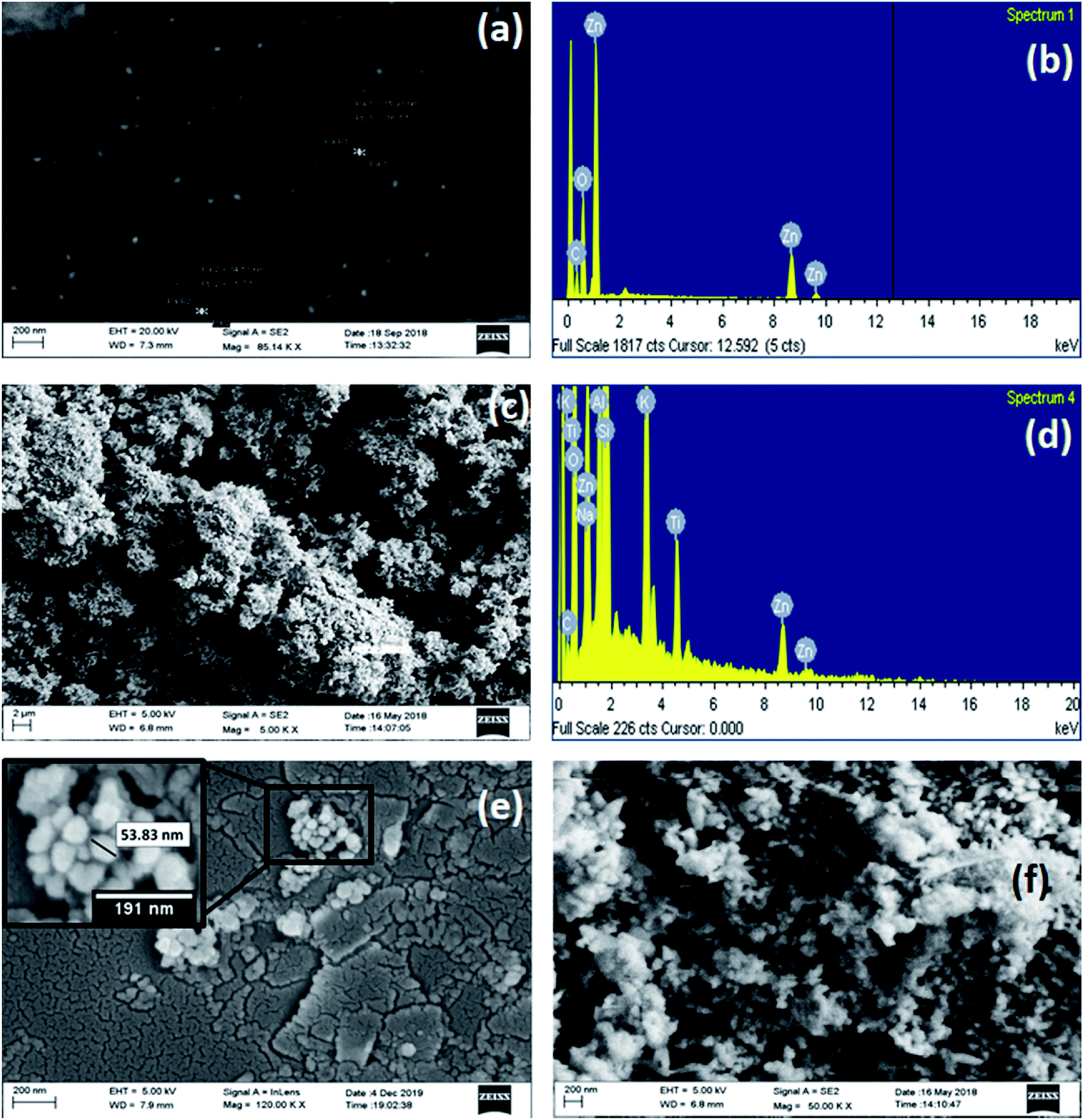 | ||
| Fig. 4 (a) SEM image of ZnO nanoparticles (magnification 85.14k×), (b) EDX images of ZnO nanoparticles, (c) SEM images of ZnO nanoparticles after adsorption of petroleum hydrocarbon (magnification 5.00k×), (d) EDX images of ZnO nanoparticles after adsorption of petroleum hydrocarbon, (e) SEM image of ZnO nanoparticles with different magnification (magnification 120.00k×) and (f) SEM images of ZnO nanoparticles after adsorption of petroleum hydrocarbon with different magnification (magnification 50.00k×). | ||
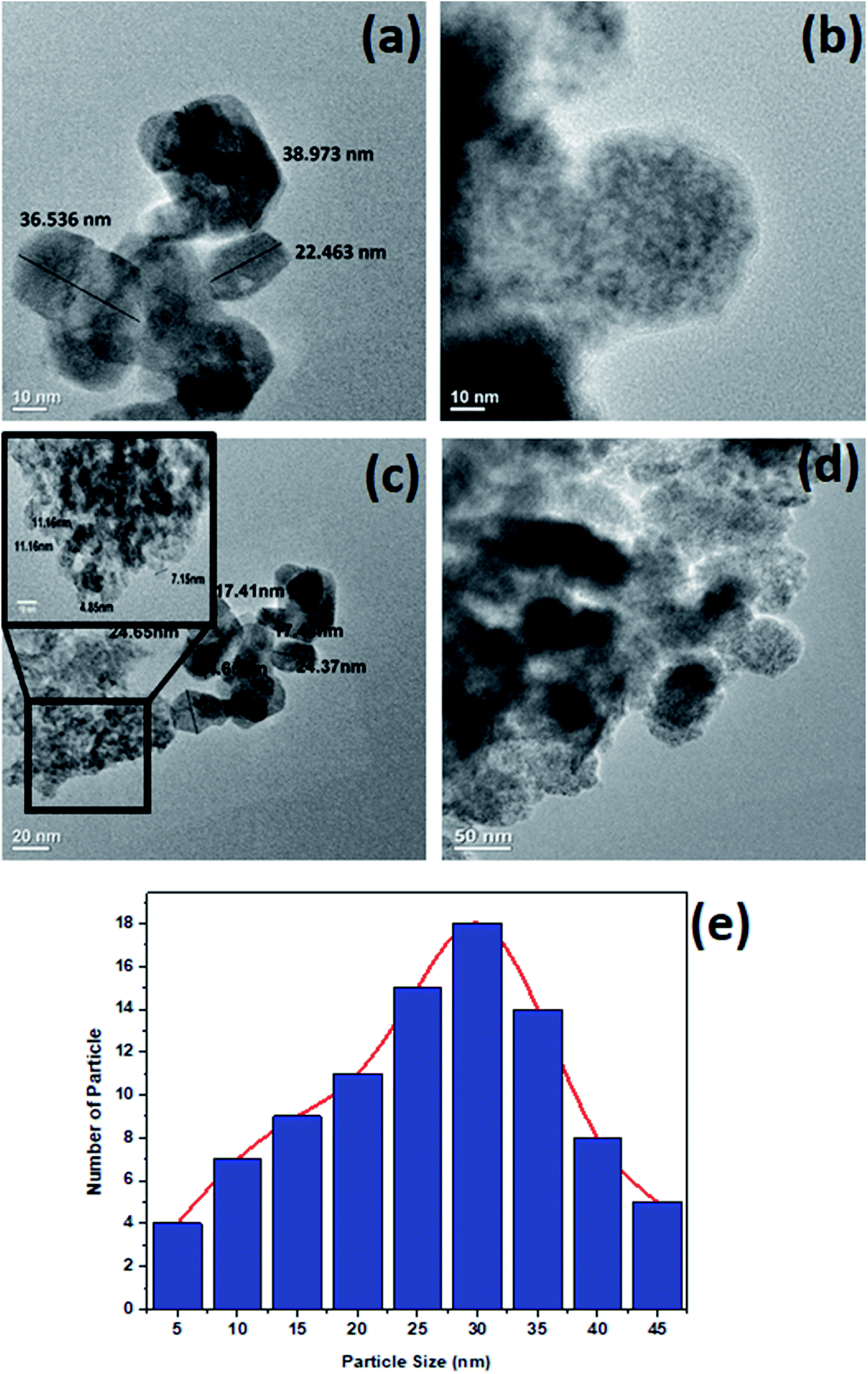 | ||
| Fig. 5 TEM images of (a) ZnO nanoparticles before adsorption of petroleum hydrocarbons, (b) ZnO nanoparticle after adsorption of petroleum hydrocarbons, (c) ZnO nanoparticles with different magnifications (in inset shows the particles with size less than 15 nm) and (d) ZnO nanoparticles after adsorption of petroleum hydrocarbons with different magnifications and (e) Histogram showing the particle size distributions of ZnO NPs. | ||
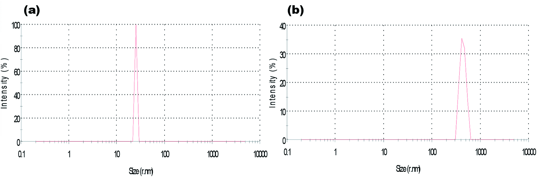 | ||
| Fig. 6 Particle size of the (a) ZnO nanoparticle and (b) ZnO nanoparticle after petroleum hydrocarbon adsorption obtained from dynamic light scattering (DLS). | ||
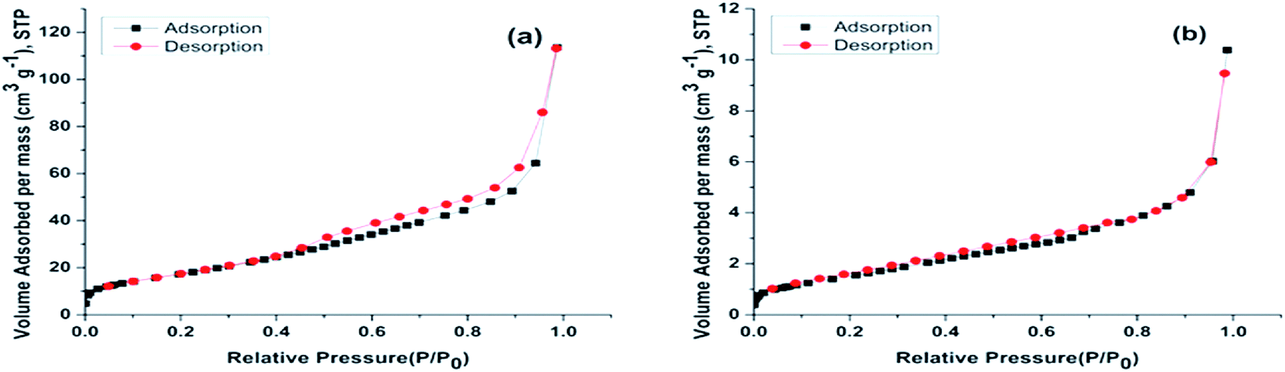
The surface area and pore size of ZnO NPs were studied using BET-N2 adsorption/desorption isotherm and are shown in Fig. 7(a). It can be observed that ZnO NPs show a type IV adsorption–desorption isotherm and H4 hysteresis loop according to the IUPAC classification.32,33 Type IV isotherm and H4 hysteresis are generally observed in complex materials with mesopores.32,34 BET-N2 adsorption/desorption study reveals that the ZnO NPs have a surface area of about 65.227 m2 g−1. In the study, the hysteresis loop of ZnO NPs (Fig. 7(a)) is larger than that of ZnO NPs after adsorption of hydrocarbon (Fig. 7(b)) at P/P0 ≥ 0.5. This confirms the presence of more mesopores in ZnO NPs (without hydrocarbon) than ZnO NPs after adsorption of hydrocarbons,32 and the same is evident from the decrease in surface area of ZnO NPs from 65.227 m2 g−1 to 5.874 m2 g−1 after adsorption of hydrocarbons.
 | ||
| Fig. 7 BET-N2 adsorption–desorption isotherm plots for (a) ZnO nanoparticle (b) ZnO nanoparticle after adsorption of petroleum hydrocarbon (PH). | ||
Further, the thermal stability of ZnO NPs before and after the adsorption of petroleum hydrocarbon was carried out by thermogravimetric analysis (TGA) (Fig. 8). ZnO NPs were found to be stable up to around 750 °C, and only ≤20% loss of mass was observed (Fig. 8(a)). While TGA graph of ZnO NPs with petroleum hydrocarbon declines (Fig. 8(b)) abruptly at around 200 °C, indicating the thermal degradation of previously adsorbed hydrocarbons by ZnO NPs.35 The higher thermal stability, which was observed in the ZnO NPs before adsorption of hydrocarbons, gives an advantage to the synthesized ZnO NPs for future usage as an adsorbing material for the treatment of contaminants up to a temperature of 750 °C.
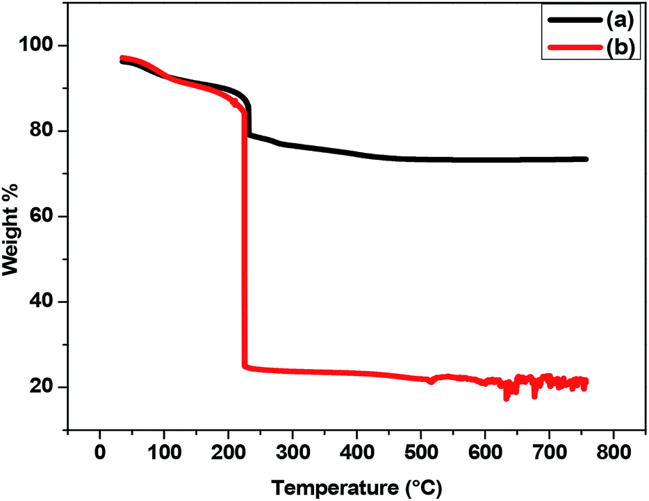 | ||
| Fig. 8 TGA thermograms of (a) ZnO NP and (b) ZnO NP after adsorption of petroleum hydrocarbon. | ||
3.4 Investigation of hydrocarbon content before and after treatment
Oil field formation water mainly consists of substituted aromatic rings, aliphatic hydrocarbons, hydrocarbons with other functional groups (–OH, –CH3, –C2H5, etc.) and various toxic heavy metals which can contaminate the natural environment when discharge untreated.36,37 Thus, in the present study, the different aromatic and aliphatic hydrocarbons and were determined using GC-MS and FTIR analysis. The TPH content of the samples was found to be 1719 ± 54.16 mg L−1 after the completion of the electrochemical reaction. It further reduced to 151 ± 12 mg L−1 when subjected to the adsorption process.000000 (Fig. 9(a)). Here, 59 compounds were of cyclic in nature, such as derivatives of naphthalene, phenanthrene, phenol, annulene, etc. and this result is similar to the work reported by Pathak et al. 2014 (ESI Table 1†).38 These types of compounds are highly toxic, mutagenic, and carcinogenic to humans or other organisms.39 Thus, the efficient removal of these hydrocarbons by the applied treatment strategy was also investigated. As already mentioned, formation water samples were treated with electrochemical reaction followed by adsorption with ZnO NPs. Finally, ZnO NPs were separated from the sample and were extracted with dichloromethane (DCM) for GC-MS analysis. The GC-MS chromatogram (Fig. 9(b)) revealed that 131 numbers of compounds were adsorbed by ZnO NPs, of which 19 were cyclic hydrocarbons (ESI Table 2†). This result proves that the other 40 cyclic hydrocarbons were degraded to simpler forms during the electrochemical reaction. Moreover, in the case of treated sample GC-MS chromatogram (Fig. 9(c)), the peak intensity becomes 1.5 with a resolution of 100000, which is almost 100 times smaller than that of the untreated sample, and not a single compound was detected in the treated sample. This justifies the efficiency of the treatment technique.
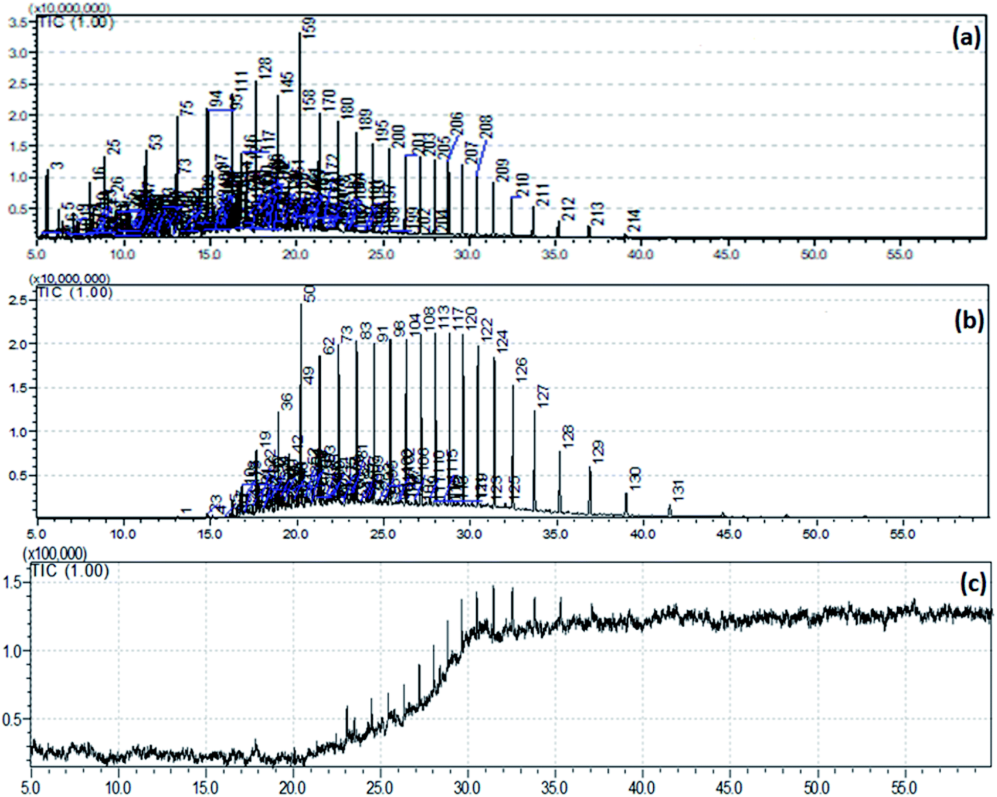 | ||
| Fig. 9 GCMS Chromatogram of (a) untreated formation water sample, (b) petroleum hydrocarbons adsorbed/absorbed by ZnO NP, and (c) treated water sample. | ||
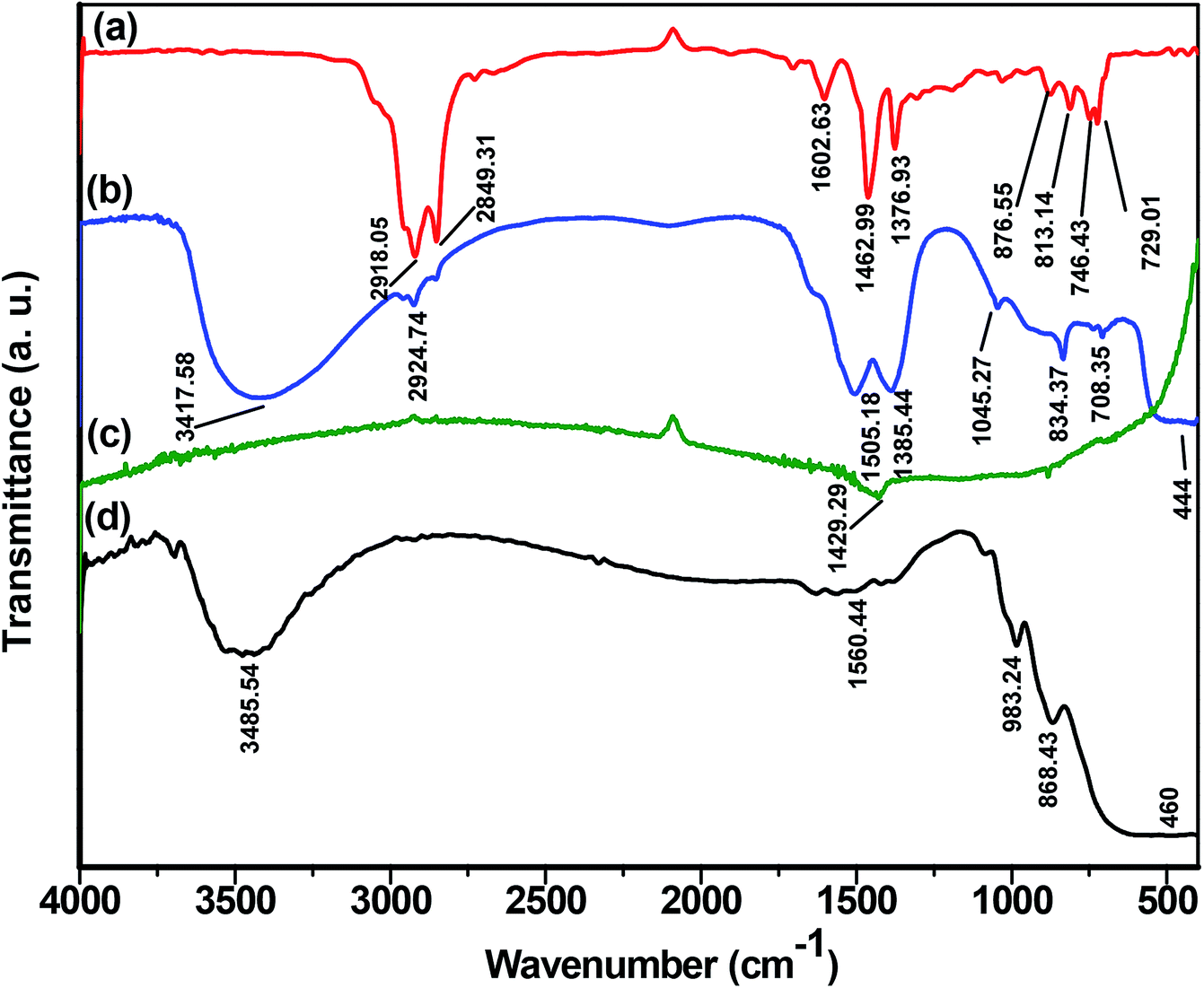 | ||
| Fig. 10 FTIR spectra of (a) untreated crude oil sample, (b) petroleum hydrocarbon (PH) adsorbed by ZnO nanoparticle (NP), (c) treated water sample and (d) synthesized ZnO NPs. | ||
On subjecting ZnO NPs after adsorption of hydrocarbons to FTIR analysis (Fig. 10(b)), an adsorption peak at 3417.58 cm−1 was observed that corresponds to the O–H stretching of adsorbed moisture content42,43 and another peak at 2924.74 cm−1 was due to the aromatic or aliphatic hydrocarbons.40 The peaks 1505.18 cm−1, 1385.44 cm−1, and 1045.27 cm−1 represent stretching and bending vibration of aromatic C![[double bond, length as m-dash]](https://www.rsc.org/images/entities/char_e001.gif) C, –CH3 and –C–H, respectively. Further, 834.37 cm−1 and 708.35 cm−1 are characteristic of aromatic rings,41 while 444 cm−1 confirms the presence of ZnO.44
C, –CH3 and –C–H, respectively. Further, 834.37 cm−1 and 708.35 cm−1 are characteristic of aromatic rings,41 while 444 cm−1 confirms the presence of ZnO.44
Fig. 10(c) represents the FTIR spectra of the treated water sample after separating from ZnO NPs. The peak of intensity 1429.29 cm−1 corresponds to CC aromatic stretching or CH3 bending mode of vibrations.41 Here, in case of the treated sample, there was no such peak representing the presence of –OH group which is because of the KBr pellet prepared by drop-casting method where the pellet containing the treated water sample is dried in an oven for 12 hours followed by vacuum desiccation for about 24 hours.
Fig. 10(d) represents the FTIR spectra of synthesized ZnO NPs. The peak at 3485.54 cm−1 indicates the presence of the –OH group.45 The peaks observed at 1560.44 cm−1, 983.24 cm−1, and 868.43 cm−1 are due to the asymmetrical and symmetrical stretching of the zinc carboxylate.45,46 While peak at 460 cm−1 corresponds to the absorption of ZnO.45–47
3.5 Variation of COD during treatment of formation water
COD can be considered as an index of pollution because the high level of COD represents a higher level of contamination in any water body.48,49 In this study, COD values were measured mainly in three different stages of reactions.(I) Untreated Sample (UT)
(II) After the completion of the electrochemical degradation reaction (EC).
(III) After completion of the adsorption process by ZnO NPs (AP)
Variation of COD at different stages of reaction is shown in Fig. 11. A continuous decline in COD can be observed in the case of electrochemical degradation and adsorption by ZnO NPs. In the untreated formation water, the initial COD was around 3118 mg L−1 that decreases to about 2089 mg L−1 after electrochemical degradation (∼33% removal) and finally decreases up to 285 mg L−1 (∼91% removal) after completion of the adsorption process (by ZnO NPs). Hence, it can be concluded that ZnO NPs can effectively remove the petroleum hydrocarbons present in the formation water samples. Table 1 shows a comparison of the efficiency of synthesized ZnO NPs for the removal of different types of industrial wastewater along with the present work.
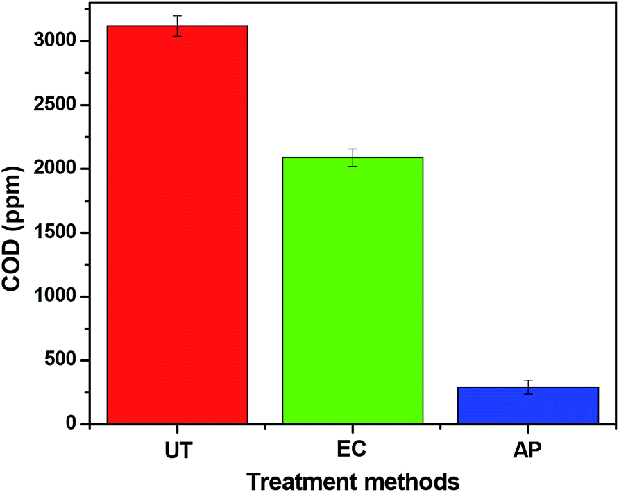 | ||
| Fig. 11 Level of COD at different stages of the reaction, (a) untreated sample-UT, (b) treated with electrochemical reaction-EC, (c) treated sample-after completion of the adsorption process by ZnO NP-AP. | ||
3.6 Reusability assessment of ZnO NPs
After the completion of the adsorption process, the ZnO NPs were treated with DCM to remove the attached (adsorbed) hydrocarbons, and then these ZnO NPs were again subjected to the treatment of formation water samples to check the reusability of the synthesized material. The analyzed GC-MS chromatogram (ESI Fig. 2(c)†) revealed that the reused NPs could remove 94 numbers of compounds from oil field formation water. The FTIR spectra (ESI Fig. 3(c)†) of reused ZnO NPs with peaks at 3417.58 cm−1 2927.84 cm−1, 2131.32 cm−1, 1440.53 cm−1, 1043.42 cm−1 and 948.68 cm−1 further confirmed the adsorption of various class of hydrocarbons. Thus, the present study demonstrates the reusability of ZnO NPs for the adsorption of hydrocarbons.4. Conclusion
ZnO NPs prepared via environment-friendly electrochemical reaction can successfully aid in the remediation of wastewater excreted by petroleum industries. SEM, TEM, and DLS analysis established the particle size of the synthesized ZnO NPs to be 35±5 nm. The successful removal of hydrocarbons was demonstrated by GC-MS, FTIR, and COD analysis. GC-MS study revealed that out of 214 determined compounds of an untreated sample, the ZnO NPs could adsorb about 131 numbers of compounds while the rest of the compounds were either partially or completely degraded during the electrochemical process. The initial COD of 3118 mg L−1 was reduced up to 285 mg L−1 (91% removal) by the treatment process. Apart from the successful degradation of the hydrocarbons without the aid of any catalyst, another primary advantage of the treatment technique is that there is no generation of secondary type pollutants. Thus, the developed treatment process can be widely used as a cost-effective and green approach for wastewater management in petroleum industries.Conflicts of interest
There are no conflicts of interest to declare.Acknowledgements
The authors are thankful to the Department of Science and Technology, Govt. of India and the Director of the Institute of Advanced Study in Science and Technology (IASST), Guwahati for financial support to execute this work. Authors would also like to express their gratitude towards Sudeshna Sharma, Dibya Jyoti Koiri and Ria Deb (Research Scholars, Environmental Chemistry Laboratory), for their support.References
- S. B. Gogoi, R. Sen, A. Rajbongshi and K. Hazarika, Characterization of oil field produced waters of Upper Assam Basin, India, International Journal of New Technologies in Science and Engineering, 2015, 2(1) Search PubMed , ISSN 2349-0780.
- A. Coelho, A. V. Castro, M. Dezotti and G. Sant’ Anna Jr, Treatment of petroleum refinery sourwater by advanced oxidation processes, J. Hazard. Mater., 2006, 137(1), 178–184 CrossRef CAS.
- T. Doggett and A. Rascoe, Global energy demand seen up 44 percent by 2030, Washington, DC, REUTERS, 2009 Search PubMed.
- B. H. Diya’uddeen, W. M. A. W. Daud and A. A. Aziz, Treatment technologies for petroleum refinery effluents: a review, Process Saf. Environ. Prot., 2011, 89(2), 95–105 CrossRef.
- O. A. Jones, D. J. Spurgeon, C. Svendsen and J. L. Griffin, A metabolomics based approach to assessing the toxicity of the polyaromatic hydrocarbon pyrene to the earthworm Lumbricus rubellus, Chemosphere, 2008, 71(3), 601–609 CrossRef CAS.
- N. Das and P. Chandran, Microbial degradation of petroleum hydrocarbon contaminants: an overview, Biotechnol. Res. Int., 2011, 2011, 941810 Search PubMed.
- Y. Wang, G. Zhang and L. Wang, Potential toxicity of phthalic acid esters plasticizer: interaction of dimethyl phthalate with trypsin in vitro, J. Agric. Food Chem., 2014, 63(1), 75–84 CrossRef PubMed.
- A. D. Venosa and X. Zhu, Biodegradation of crude oil contaminating marine shorelines and freshwater wetlands, Spill Sci. Technol. Bull., 2003, 8(2), 163–178 CrossRef CAS.
- A. Fakhru'l-Razi, A. Pendashteh, L. C. Abdullah, D. R. A. Biak, S. S. Madaeni and Z. Z. Abidin, Review of technologies for oil and gas produced water treatment, J. Hazard. Mater., 2009, 170(2–3), 530–551 CrossRef PubMed.
- C. A. Martinez-Huitle and S. Ferro, Electrochemical oxidation of organic pollutants for the wastewater treatment: direct and indirect processes, Chem. Soc. Rev., 2006, 35(12), 1324–1340 RSC.
- S. Azizi, M. Mahdavi Shahri and R. Mohamad, Green Synthesis of Zinc Oxide Nanoparticles for Enhanced Adsorption of Lead Ions from Aqueous Solutions: Equilibrium, Kinetic and Thermodynamic Studies, Molecules, 2017, 22(6), 831 CrossRef PubMed.
- A. Thanapimmetha, P. Srinophakun, S. Amat and M. Saisriyoot, Decolorization of molasses-based distillery wastewater by means of pulse electro-Fenton process, J. Environ. Chem. Eng., 2017, 5(3), 2305–2312 CrossRef CAS.
- H. Zhao, L. Qian, X. Guan, D. Wu and G. Zhao, Continuous bulk FeCuC aerogel with ultradispersed metal nanoparticles: an efficient 3D heterogeneous electro-Fenton cathode over a wide range of pH 3–9, Environ. Sci. Technol., 2016, 50(10), 5225–5233 CrossRef CAS PubMed.
- A. Qian, S. Yuan, P. Zhang and M. Tong, A new mechanism in electrochemical process for arsenic oxidation: production of H2O2 from anodic O2 reduction on the cathode under automatically developed alkaline conditions, Environ. Sci. Technol., 2015, 49(9), 5689–5696 CrossRef CAS PubMed.
- N. Oturan, E. D. Van Hullebusch, H. Zhang, L. Mazeas, H. L. N. Budzinski and K. Le Menach, et al., Occurrence and removal of organic micropollutants in landfill leachates treated by electrochemical advanced oxidation processes, Environ. Sci. Technol., 2015, 49(20), 12187–12196 CrossRef CAS PubMed.
- R. Ciriminna, L. Albanese, F. Meneguzzo and M. Pagliaro, Hydrogen peroxide: A Key chemical for today's sustainable development, ChemSusChem, 2016, 9(24), 3374–3381 CrossRef CAS PubMed.
- W. C. Ellis, C. T. Tran, R. Roy, M. Rusten, A. Fischer and A. D. Ryabov, et al., Designing green oxidation catalysts for purifying environmental waters, J. Am. Chem. Soc., 2010, 132(28), 9774–9781 CrossRef CAS PubMed.
- J. Radjenovic and D. L. Sedlak, Challenges and opportunities for electrochemical processes as next-generation technologies for the treatment of contaminated water, Environ. Sci. Technol., 2015, 49(19), 11292–11302 CrossRef CAS PubMed.
- I. Ghiloufi, J. El Ghoul, A. Modwi and L. El Mir, Ga-doped ZnO for adsorption of heavy metals from aqueous solution, Mater. Sci. Semicond. Process., 2016, 42, 102–106 CrossRef CAS.
- A. P. H. Association and A. W. W. Association, Standard methods for the examination of water and wastewater, American public health association, 1989 Search PubMed.
- Organization W. H., Guidelines for drinking water quality, Geneva, Switzerland, World Health Organization, 2011 Search PubMed.
- E. W. Wilson, W. A. Hamilton, H. R. Kennington, B. Evans, N. W. Scott and W. B. DeMore, Measurement and estimation of rate constants for the reactions of hydroxyl radical with several alkanes and cycloalkanes, J. Phys. Chem. A, 2006, 110(10), 3593–3604 CrossRef CAS PubMed.
- T. Pauporté and D. Lincot, Hydrogen peroxide oxygen precursor for zinc oxide electrodeposition II—mechanistic aspects, J. Electroanal. Chem., 2001, 517(1–2), 54–62 CrossRef.
- S. S. Kumar, P. Venkateswarlu, V. R. Rao and G. N. Rao, Synthesis, characterization and optical properties of zinc oxide nanoparticles, Int. Nano Lett., 2013, 3(1), 30 CrossRef.
- G. Sangeetha, S. Rajeshwari and R. Venckatesh, Green synthesis of zinc oxide nanoparticles by aloe barbadensis miller leaf extract: Structure and optical properties, Mater. Res. Bull., 2011, 46(12), 2560–2566 CrossRef CAS.
- H. Wei, Y. Wu, N. Lun and C. Hu, Hydrothermal synthesis and characterization of ZnO nanorods, Mater. Sci. Eng. A, 2005, 393(1–2), 80–82 CrossRef.
- N. Olaru, G. Calin and L. Olaru, Zinc oxide nanocrystals grown on cellulose acetate butyrate nanofiber mats and their potential photocatalytic activity for dye degradation, Ind. Eng. Chem. Res., 2014, 53(46), 17968–17975 CrossRef CAS.
- X. Feng, Y. Yan, B. Wan, W. Li, D. P. Jaisi and L. Zheng, et al., Enhanced dissolution and transformation of ZnO nanoparticles: the role of inositol hexakisphosphate, Environ. Sci. Technol., 2016, 50(11), 5651–5660 CrossRef CAS PubMed.
- Y. Su, S. Li, D. He, D. Yu, F. Liu and N. Shao, et al., MOF-Derived Porous ZnO Nanocages/rGO/Carbon Sponge-Based Photocatalytic Microreactor for Efficient Degradation of Water Pollutants and Hydrogen Evolution, ACS Sustainable Chem. Eng., 2018, 6(9), 11989–11998 CrossRef CAS.
- C. Jayaseelan, A. A. Rahuman, A. V. Kirthi, S. Marimuthu, T. Santhoshkumar and A. Bagavan, et al., Novel microbial route to synthesize ZnO nanoparticles using Aeromonas hydrophila and their activity against pathogenic bacteria and fungi, Spectrochim. Acta, Part A, 2012, 90, 78–84 CrossRef CAS PubMed.
- M. Khuhawar, M. A. Mirza and T. Jahangir, Determination of metal ions in crude oils, Crude oil emulsions-Composition stability and characterization, InTech, 2012 Search PubMed.
- M. Thommes, Physical adsorption characterization of nanoporous materials, Chem. Ing. Tech., 2010, 82(7), 1059–1073 CrossRef CAS.
- K. S. Sing and R. T. Williams, Physisorption hysteresis loops and the characterization of nanoporous materials, Adsorpt. Sci. Technol., 2004, 22(10), 773–782 CrossRef CAS.
- H. Medhi and K. G. Bhattacharyya, Kinetic and mechanistic studies on adsorption of Cu (II) in aqueous medium onto montmorillonite K10 and its modified derivative, New J. Chem., 2017, 41(22), 13533–13552 RSC.
- N. Ismail, E. Seber and B. Hascakir, Water and aromatics fraction interaction at elevated temperature and their impact on reaction kinetics of in situ combustion, J. Pet. Sci. Eng., 2018, 169, 24–32 CrossRef CAS.
- M. Pathak, A. Devi, K. Bhattacharyya, H. Sarma, S. Subudhi and B. Lal, Production of a non-cytotoxic bioflocculant by a bacterium utilizing a petroleum hydrocarbon source and its application in heavy metal removal, RSC Adv., 2015, 5(81), 66037–66046 RSC.
- P. D. Lundegard and J. R. Knott, Polar organics in crude oil and their potential impacts on water quality, Proceedings of the 2001 conference on petroleum hydrocarbons and organic chemicals in groundwater, National Ground Water Association, Westerville, 2001 Search PubMed.
- M. Pathak, A. Devi, H. K. Sarma and B. Lal, Application of bioflocculating property of Pseudomonas aeruginosa strain IASST201 in treatment of oil-field formation water, J. Basic Microbiol., 2014, 54(7), 658–669 CrossRef CAS.
- S. K. Samanta, O. V. Singh and R. K. Jain, Polycyclic aromatic hydrocarbons: environmental pollution and bioremediation, Trends Biotechnol., 2002, 20(6), 243–248 CrossRef CAS PubMed.
- M. Sun, X. X. Ma, Q. X. Yao, R. C. Wang, Y. X. Ma and G. Feng, et al., GC-MS and TG-FTIR study of petroleum ether extract and residue from low temperature coal tar, Energy Fuels, 2011, 25(3), 1140–1145 CrossRef CAS.
- D. L. Pavia, G. M. Lampman, G. S. Kriz and J. A. Vyvyan, Introduction to spectroscopy, Cengage Learning, 2014 Search PubMed.
- S. C. Pillai, J. M. Kelly, D. E. McCormack, P. O'Brien and R. Ramesh, The effect of processing conditions on varistors prepared from nanocrystalline ZnO, J. Mater. Chem., 2003, 13(10), 2586–2590 RSC.
- A. Jimenez-Gonzalez, J. A. S. Urueta and R. Suarez-Parra, Optical and electrical characteristics of aluminum-doped ZnO thin films prepared by solgel technique, J. Cryst. Growth, 1998, 192(3–4), 430–438 CrossRef CAS.
- V. Etacheri, R. Roshan and V. Kumar, Mg-doped ZnO nanoparticles for efficient sunlight-driven photocatalysis, ACS Appl. Mater. Interfaces, 2012, 4(5), 2717–2725 CrossRef CAS PubMed.
- A. K. Zak, W. A. Majid, M. Darroudi and R. Yousefi, Synthesis and characterization of ZnO nanoparticles prepared in gelatin media, Mater. Lett., 2011, 65(1), 70–73 CrossRef CAS.
- K. Ghule, A. V. Ghule, B. J. Chen and Y. C. Ling, Preparation and characterization of ZnO nanoparticles coated paper and its antibacterial activity study, Green Chem., 2006, 8(12), 1034–1041 RSC.
- L. H. Li, J. C. Deng, H. R. Deng, Z. L. Liu and L. Xin, Synthesis and characterization of chitosan/ZnO nanoparticle composite membranes, Carbohydr. Res., 2010, 345(8), 994–998 CrossRef CAS PubMed.
- S. Mor, K. Ravindra, R. Dahiya and A. Chandra, Leachate characterization and assessment of groundwater pollution near municipal solid waste landfill site, Environ. Monit. Assess., 2006, 118(1–3), 435–456 CrossRef CAS.
- M. R. Bonfá, M. J. Grossman, E. Mellado and L. R. Durrant, Biodegradation of aromatic hydrocarbons by Haloarchaea and their use for the reduction of the chemical oxygen demand of hypersaline petroleum produced water, Chemosphere, 2011, 84(11), 1671–1676 CrossRef.
- R. D. C. Soltani, S. Jorfi, M. Safari and M. S. Rajaei, Enhanced sonocatalysis of textile wastewater using bentonite-supported ZnO nanoparticles: Response surface methodological approach, J. Environ. Manag., 2016, 179, 47–57 CrossRef PubMed.
- A. Khataee, A. Karimi, S. Arefi-Oskoui, R. D. C. Soltani, Y. Hanifehpour and B. Soltani, et al., Sonochemical synthesis of Pr-doped ZnO nanoparticles for sonocatalytic degradation of Acid Red 17, Ultrason. Sonochem., 2015, 22, 371–381 CrossRef CAS PubMed.
- S. M. Dehaghi, B. Rahmanifar, A. M. Moradi and P. A. Azar, Removal of permethrin pesticide from water by chitosan–zinc oxide nanoparticles composite as an adsorbent, J. Saudi Chem. Soc., 2014, 18(4), 348–355 CrossRef.
- Z. Rafiq, R. Nazir, M. R. Shah and S. Ali, Utilization of magnesium and zinc oxide nano-adsorbents as potential materials for treatment of copper electroplating industry wastewater, J. Environ. Chem. Eng., 2014, 2(1), 642–651 CrossRef CAS.
- J. Choina, A. Bagabas, C. Fischer, G. U. Flechsig, H. Kosslick and A. Alshammari, et al., The influence of the textural properties of ZnO nanoparticles on adsorption and photocatalytic remediation of water from pharmaceuticals, Catal. Today, 2015, 241, 47–54 CrossRef CAS.
- P. Saharan, G. R. Chaudhary, S. Lata, S. Mehta and S. Mor, Ultra fast and effective treatment of dyes from water with the synergistic effect of Ni doped ZnO nanoparticles and ultrasonication, Ultrason. Sonochem., 2015, 22, 317–325 CrossRef CAS PubMed.
Footnote |
| † Electronic supplementary information (ESI) available. See DOI: 10.1039/c9ra09202a |
| This journal is © The Royal Society of Chemistry 2020 |