
 Open Access Article
 This Open Access Article is licensed under a Creative Commons Attribution-Non Commercial 3.0 Unported Licence
Fabrication of a composite anion exchange membrane with aligned ion channels for a high-performance non-aqueous vanadium redox flow battery
Jae-Hun Kima,
Seungbo Ryu a,
Sandip Mauryab,
Ju-Young Leea,
Ki-Won Sunga,
Jae-Suk Leec and
Seung-Hyeon Moon*a
a,
Sandip Mauryab,
Ju-Young Leea,
Ki-Won Sunga,
Jae-Suk Leec and
Seung-Hyeon Moon*a
aSchool of Earth Sciences and Environmental Engineering, Gwangju Institute of Science and Technology (GIST), 123 Cheomdan-Gwagiro (Oryong-dong), Buk-gu, Gwangju, 61005, Korea. E-mail: shmoon@gist.ac.kr
bMaterials Synthesis and Integrated Devices, MPA-11, Materials Physics and Applications Division, Los Alamos National Laboratory, Los Alamos, NM 8745, USA
cSchool of Materials Sciences and Environmental Engineering, Gwangju Institute of Science and Technology (GIST), 123 Cheomdan-Gwagiro (Oryong-dong), Buk-gu, Gwangju, 61005, Korea
First published on 30th January 2020
Abstract
Fabrication of high-conductivity ion exchange membranes (IEMs) is crucial to improve the performance of non-aqueous vanadium redox flow batteries (NAVRFBs). In the present work, anion exchange membranes with high-conductivity were fabricated by aligning ion channels of the polymer electrolyte impregnated in porous polytetrafluoroethylene (PTFE) under electric fields. It was observed that the ion channels of the polymer electrolyte were uniformly orientated in the atomic-force microscopy image. Its morphological change could minimize detouring of the transport of BF4− ions. The results showed through-plane conductivity was improved from 12.7 to 33.1 mS cm−1. The dimensional properties of the fabricated membranes were also enhanced compared with its cast membrane owing to the reinforcing effect of the substrate. Especially, the NAVRFB assembled with the optimized membrane showed increased capacities, with a 97% coulombic efficiency and 70% energy efficiency at 80 mA cm−2. Furthermore, the optimized membrane made it possible to operate the NAVRFB at 120 mA cm−2. Its operating current density was 120 times higher than that of a frequently used AHA membrane for RFBs.
1. Introduction
In the twenty-first century, demand has risen for renewable storage technologies to replace depleted fossil fuels. Redox flow batteries (RFBs) are one of the most promising energy storage systems. Lawrence Thaller introduced modern RFBs in the National Aeronautics and Space Administration in the 1970s.1 Since then, several redox metal species have been applied, such as vanadium, cobalt, manganese, and zinc, owing to the excellent reversibility of their reduction and oxidation.2–7 To date, the development of RFBs has mostly focused on aqueous systems because of their high performance in operating charge/discharge cycles compared with non-aqueous systems. However, aqueous media strictly limit the operating potential of these RFBs under 2 V, owing to facile and unwanted water electrolysis above this potential.8 To overcome the problem of low-operation voltage, non-aqueous electrolytes show promise, owing to their wide electro-chemical window. In particular, vanadium ligands of excellent reversibility have been mostly applied in non-aqueous redox flow batteries (NARFBs). However, most applied charge carriers in non-aqueous media migrate quite slowly, with poor ion conductivity, compared with charge carriers in aqueous media.9,10As shown in Table 1, we investigated the molar conductivity for the most commonly used charge carriers between ARFBs and NARFBs. The molar conductivity of the supporting ion varies according to the type of an organic solvent. Gong et al. reported that the low viscosity of the organic solvent increases the molar conductivity of the supporting ion.12 Molar conductivities of the most often used BF4− ions in acetonitrile (ACN) are remarkably lower than those of protons in aqueous media.
| Supporting ion | Molar conductivities of charge carriersa (S cm2 mol−1) | |||
|---|---|---|---|---|
| Water | Acetonitrile | Propylene carbonate | Ref. | |
| a Limiting molar conductivities were measured at room temperature. | ||||
| H+ | 349.6 | — | — | 11 |
| SO42− | 160 | — | — | |
| Cl− | 76.4 | — | — | |
| TEA+ (tetraethyl ammonium ion) | 32.7 | 85.1 | 13.5 | 12 |
| TBA+ (tetrabutyl ammonium ion) | 61.6 | 19.5 | 9.09 | |
| BF4− (tetrafluoroborate ion) | 75.1 | 108.5 | 20.4 | |
| PF6− (hexafluorophosphate ion) | 65.5 | 102.8 | 17.9 | |
Garcia et al. reported measuring the ion conductivity for commercial IEMs by using a four-probe cell, as shown in Table 2.13 Normally, the molar conductivities of charge carriers significantly influence the ion conductivities of IEMs.
| IEM | Type | Supporting ion | Solvent | Thickness (μm) | Membrane electrical resistance (MER) (Ω cm2) | Conductivity (mS cm−1) |
|---|---|---|---|---|---|---|
| a Ion conductivities for IEMs were measured after soaking in 0.5 M TBABF4, TEABF4, and TEAPF6 for five days. | ||||||
| Nafion 1035 | Cation exchange membrane | H+ | Water | 105 | 0.1 | 86.0 |
| TEA+ | ACN | 1.0 | 10.7a | |||
| TBA+ | ACN | 1.9 | 5.6a | |||
| AHA | Anion exchange membrane | Cl− | Water | 220 | 8.8 | 2.5 |
| BF4− | ACN | 46.2 | 0.48a | |||
| PF6− | ACN | 95.3 | 0.23a | |||
In non-aqueous supporting electrolytes, IEMs showed remarkably lower conductivities compared with aqueous supporting electrolytes. In addition, the ion conductivity of the AHA membrane was reversed, even though the molar conductivity of BF4− ions in ACN was higher than the molar conductivity of Cl− in water. It is surmised that the AHA membrane does not provide suitable conditions in organic media.4,14 For this reason, electroneutrality cannot be rapidly recovered in NARFBs, which result in poor performance and operating current density. To improve the performance with a high current density, suitable separators or IEMs are among the core components. In this study, we developed novel IEMs for the NAVRFB to improve its performance at a high current density.
In most NAVRFBs, anion exchange membranes (AEMs) are employed because of their compatibility with the ion selectivity of supporting ions (BF4−). Their cells have been constructed using commercial AEMs (e.g., AHA, ASTOM, Japan, FAP4; FuMA-Tech, Germany), which were originally used for desalination and electrodialysis in water applications.14 Therefore, the membranes may not have the appropriate characteristics (e.g., ion conductivity, ion perm-selectivity, MER) in NAVRFB systems. To overcome these drawbacks, AEMs have been developed by various methods: an advanced AEM based on blending the poly(vinyl chloride),15 using organic–inorganic materials,16 or coating the interpenetrating polymer network.17
Most notably, pore-filled AEMs have been fabricated to improve the chemical and mechanical stabilities in RFB systems. These membranes are usually prepared by a straightforward method. Porous substrates (e.g., polypropylene, polyethylene, PTFE) are filled with ion-exchange resins or polymer electrolytes, followed by a drying step. This concept was proposed by Yamaguchi et al., because the supporting substrates can complement the mechanical and chemical stabilities of IEMs.18–20 Enhanced mechanical strength contributes to reducing MER, since the pore-filled IEMs are prepared as a thin film. With these advantages, the pore-filled membranes can be applied in energy conversion and storage systems by introducing adequate ion-exchange resins or solutions. However, the conductivities of pore-filled membranes are generally lower than those of casting IEMs owing to the non-conductive property of supporting substrates.
In the previous study, we reported that conductivities of quaternary-aminated poly (2,6-dimethyl-1,4-phenylene oxide) (QPPO) membranes were improved by aligning the ion channels on the nano scale.21 Typically, ion channels in the IEMs are entangled in a random direction, in accordance with thermodynamic theory. In a QPPO membrane, anions can freely migrate through the entangled ion channels (or tunnels), which consist of dipole groups (positively charged groups and counter ions) based on polymer backbones.22 However, the non-oriented ion channels have the effect of delaying the migration of specific ions in IEMs. The electrically aligned QPPO membrane can be fabricated under the electric field exerted externally. Its noticeable effect is the improvement of ion conductivity of the QPPO membrane because the aligned ion channels assist the rapid ion migration with a minimized detour. The electrically treated QPPO membrane was prepared by casting the QPPO solutions between a doctor blade and a metal plate as electrodes supplying DC current.
The advantage of this method is that it allows the fabrication of a high-conductivity membrane in low-consumption energy without additional agents. The electrically treated QPPO membrane has the merits which maintain its original properties, such as ion selectivity and ion exchange capacity. However, the aligned QPPO membrane may be dimensionally unstable in organic media and hard to fabricate as a thin film for the low MER because of its intrinsic mechanical instability.
To overcome such problems, this study suggests that the QPPO polymer loaded into a porous PTFE is electrically treated by applying a DC electric field. Its AEM can be improved by both the pore-filling method and the effects of the aligned ion channels. As a typical method, a supporting substrate of microporous structure is densely filled with QPPO solution as seen Fig. 1(a). After that, the composite QPPO (cQPPO) membrane is fabricated by a curing process. However, anions must be still detoured by following the entangled ion channels of the QPPO polymer.
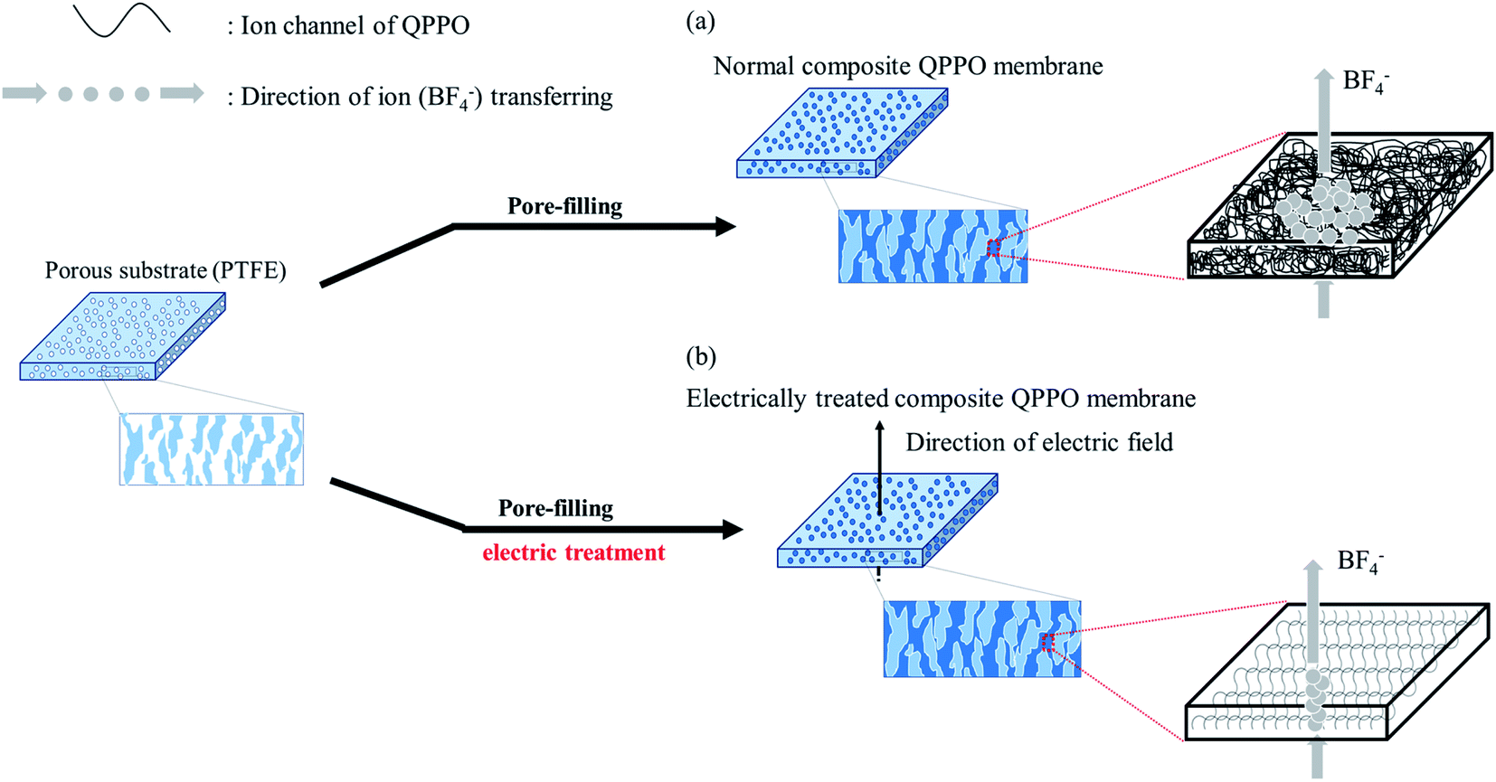 | ||
| Fig. 1 Process of fabricating the cQPPO membrane: (a) the general fabrication method of the cQPPO membrane and tortuous ion channels of the QPPO polymer, (b) electrically treated QPPO membrane with aligned ion channels of the QPPO polymer in the substrate. | ||
The electrically aligned cQPPO membrane can be fabricated by applying an electric field as seen in Fig. 1(b). Ion channels of the QPPO in the substrate are aligned following the direction of the electric field. Owing to the oriented ion channels of the QPPO polymer, the anion can be directly transferred. Accordingly, the electrically treated cQPPO membranes can have high ion conductivity, with enhanced stabilities in non-aqueous solvents. Besides, the formation of the thin film and aligned ion channels can contribute to lowering the MER.
The cQPPOs can be prepared by combining the two concepts, applying the modified continuous caster, as shown in Fig. 2. This device has the merit of being a continuous manufacturing process of the membrane on a lab scale.23 The direction of the ion channels and thickness of the membrane are determined between two casting metal blades at the same time.
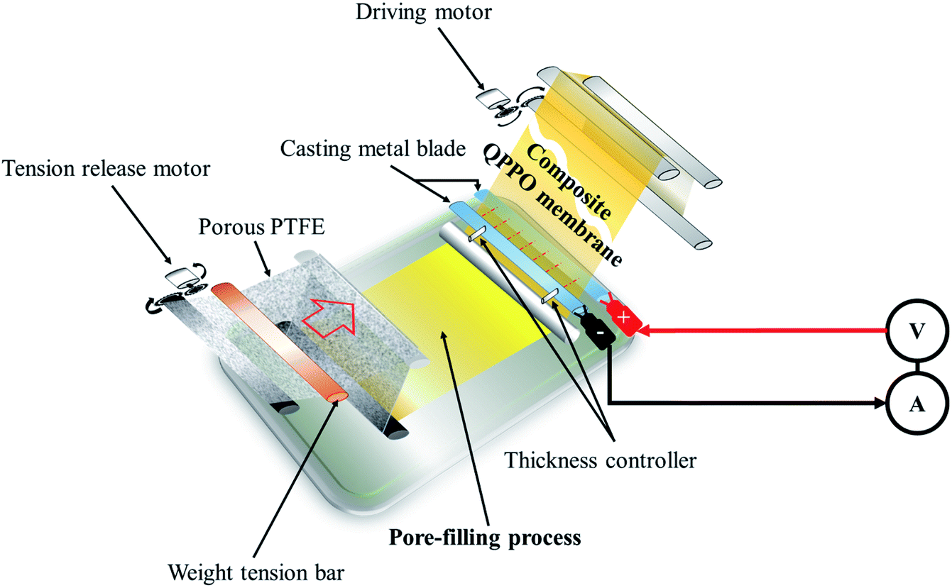 | ||
| Fig. 2 The process of preparing the cQPPO of the aligned ion channels using a modified continuous caster. | ||
In this study, fabricated cQPPO membranes were observed for their conductivity, dimensional properties, morphological change, and other parameters. Also, three types of membranes (commercial AHA, non-aligned, and aligned cQPPO) were employed in a single cell to evaluate the performance.
2. Experimental section
2.1 Materials
A porous PTFE (thickness: 15 μm, pore size: 0.45 μm, porosity: 70%) was provided by Sumitomo Electric Industries Ltd. (HHP-045-15, Japan), and the commercial AHA membrane (Neosepta, Japan) was purchased as a reference membrane. The chloromethyl ethyl ether (CMEE) (95%), poly(2,6-dimethyl-1,4-phenylene oxide) (PPO), zinc chloride (reagent grade, ≥98%), trimethylamine (TMA) (∼45 wt% in H2O), and 1-methyl-2-pyrrolidone (NMP, anhydrous, 99.5%) were bought from Sigma-Aldrich to prepare the QPPO polymer. Monochlorobenzene (99% extra pure) and methanol (assay 99.6%) were provided by OCI Co. Ltd. Acetonitrile (anhydrous, 99.8%) and vanadium acetylacetonate (V(acac)3) were obtained from Sigma-Aldrich. Deionized water (resistivity >18.2 MΩ) was used to purify the chloromethylated PPO and was obtained using a Millipore system. The supporting electrolyte of TEABF4 at a one-molar concentration (Panax E-tec Co. Ltd., South Korea) was used to prepare an active electrolyte. Porous carbon felts (Nippon Carbon Co. Ltd., Japan) were used for the electrodes in the NAVRFB.2.2 Preparation of the QPPO polymer solution
To prepare the QPPO polymer solution, 15.4 g of PPO was dissolved in 80 mL mono-chlorobenzene for 1 h at room temperature, using a mechanical stirrer with a condenser; this was carried out in a three-neck round flask. Afterward, zinc chloride (0.77 g) was added and mixed in the liquefied PPO for 20 min at 50 °C. A CMEE (25 mL) was slowly dropped into a three-neck round flak, and a homogeneous solution was continuously stirred for one day, maintaining a warm temperature. The solution state of chloromethylated PPO (CPPO) was precipitated using methanol. The solidified CPPO was cleaned several times with deionized water (DI water) and dried in a 60 °C oven for one day. Before the synthetic process of the QPPO, CPPO (10 g) was dissolved in 46.0 mL of NMP in a 50 °C oven for one day, and the polymer solution of QPPO was synthesized by adding 3.07 mL of TMA in the dissolved CPPO and then stirred for one day. Fig. 3 presents the synthetic scheme from PPO to QPPO.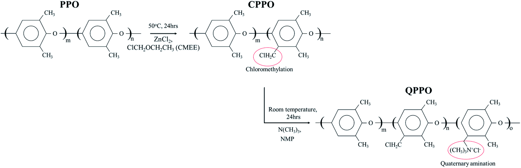 | ||
| Fig. 3 The systemic process from PPO to QPPO. The polymer solution of the QPPO was synthesized by chloromethylation (first step) and quaternization (second step). | ||
2.3 Preparation of aligned cQPPO membranes by applying an electric field
To prepare the electrically treated pore-filled QPPO membrane, the device was modified so that the casting metal blades were connected to a power supply (6613C, Agilent) and pico-ammeter (6487, Keithley), as shown in Fig. 2.In the process of preparing the cQPPO membranes, the tension of the substrate was retained using two motors (release and driving motor). The pores of the substrate were filled by immersing a sufficient QPPO solution using a brush stroke in the pore-filling process. In addition, the pore-filled QPPO membrane was moved at a constant velocity (5 mm min−1), while the porous PTFE was immersed in the QPPO polymer, followed by aligning ion channels in a through-plane direction between two casting metal blades under various electric fields (0, 1, 1.25, and 1.5 V). At the same time, a change in current was observed according to the intensity of the supplied voltage, using a pico-ammeter for aligning the ion channels. The fabricated cQPPO under electrical treatment remained at room temperature for one day.
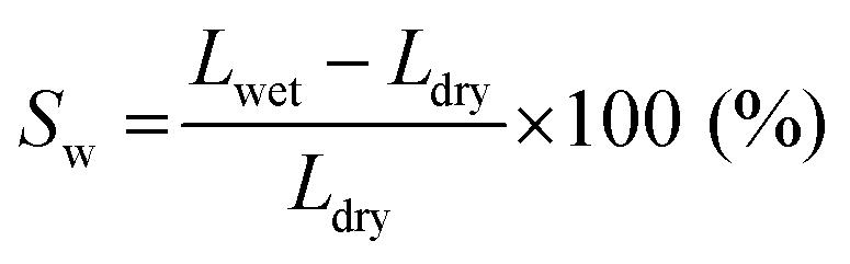
2.4 Measurement of swelling ratio, solvent uptake, tensile strength, and elongation at break
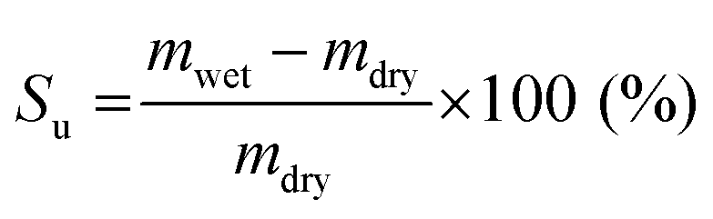
The swelling ratio and solvent uptake are useful parameters for evaluating the dimensional stability of membranes. To estimate the dimensional stability, samples were immersed in ACN for one day before measurement. In addition, the length and weight of the wet samples were measured after cleaning the membrane surface using soft papers. The samples were then dried in a 60 °C oven for one day to obtain the length and weight of the dried samples.The swelling ratio was calculated by measuring the change in length of swollen and dried membranes, as in eqn (1).
 | (1) |
Likewise, the solvent uptake was obtained by weighing the wet and dried membranes, as described in eqn (2).
 | (2) |
To measure the mechanical properties, samples were prepared in a dumbbell shape. The mechanical strength of the specimens was measured using a universal technical machine (TO-101, Testone, Korea) at a crosshead speed of 10 mm min−1. To examine the mechanical properties, averages of three tests of the tensile strength and elongation of a break for samples were taken.
2.5 Measurement of transport number
The transport number of the membrane was measured using a two-compartment cell of the Teflon material. The membranes were soaked in diluted 0.5 M TEABF4 in ACN for 24 h and then fixed between electrolytic reservoirs. Afterward, TEABF4 of 0.01 M and 0.05 M were poured in and stirred to maintain the uniformity of the entire concentration in the respective reservoirs. Then, the potential was observed by connecting Ag/Ag+ electrodes in a battery cycler (580 Battery Test System, Scribner Associates. Inc, Germany) in an argon-filled glove box (IN 1000, M.O. Tech., South Korea). The transport number was calculated by eqn (3), from the measured potential.
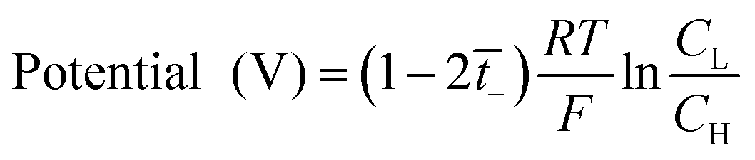 | (3) |
 is the transport number of the AEM.
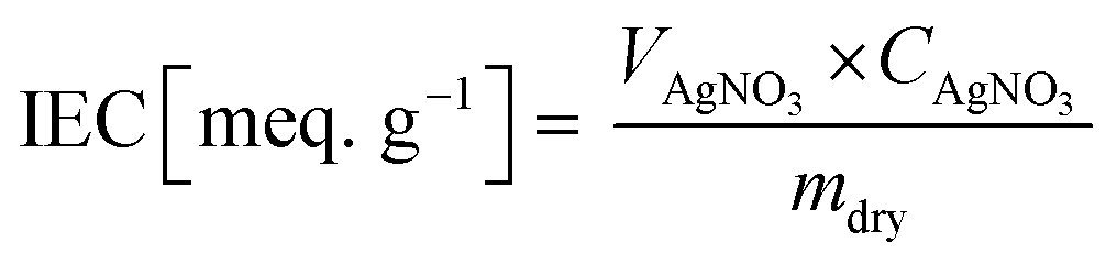
2.6 Titration of ion exchange capacity (IEC)
The IEC of the fabricated membranes was measured by titrating AgNO3−. First, the membrane was immersed in 1 M NaCl for one day to transform Cl− ions in their functional groups. The NaCl solution at the membrane surface was removed using DI water. The sample was then soaked in 0.5 M Na2CO3 for one day. The sample, which was substituted in the form of carbonated ions, was titrated using AgNO3, and then the weight of the dried sample after being baked in a 50 °C oven for one day was measured. The IEC values were estimated according to eqn (4).
 | (4) |
2.7 Electrical resistance and ionic conductivity of the membranes
To observe the ionic conductivity, the membranes were soaked in 1 M TEABF4 in ACN as a pre-treatment step for 24 h. Then, the resistance of the membranes was measured by a clip cell that scanned from 106 to 10−5 Hz using an impedance spectroscope (AutoLab, PGSTAT30), as shown in Fig. 4.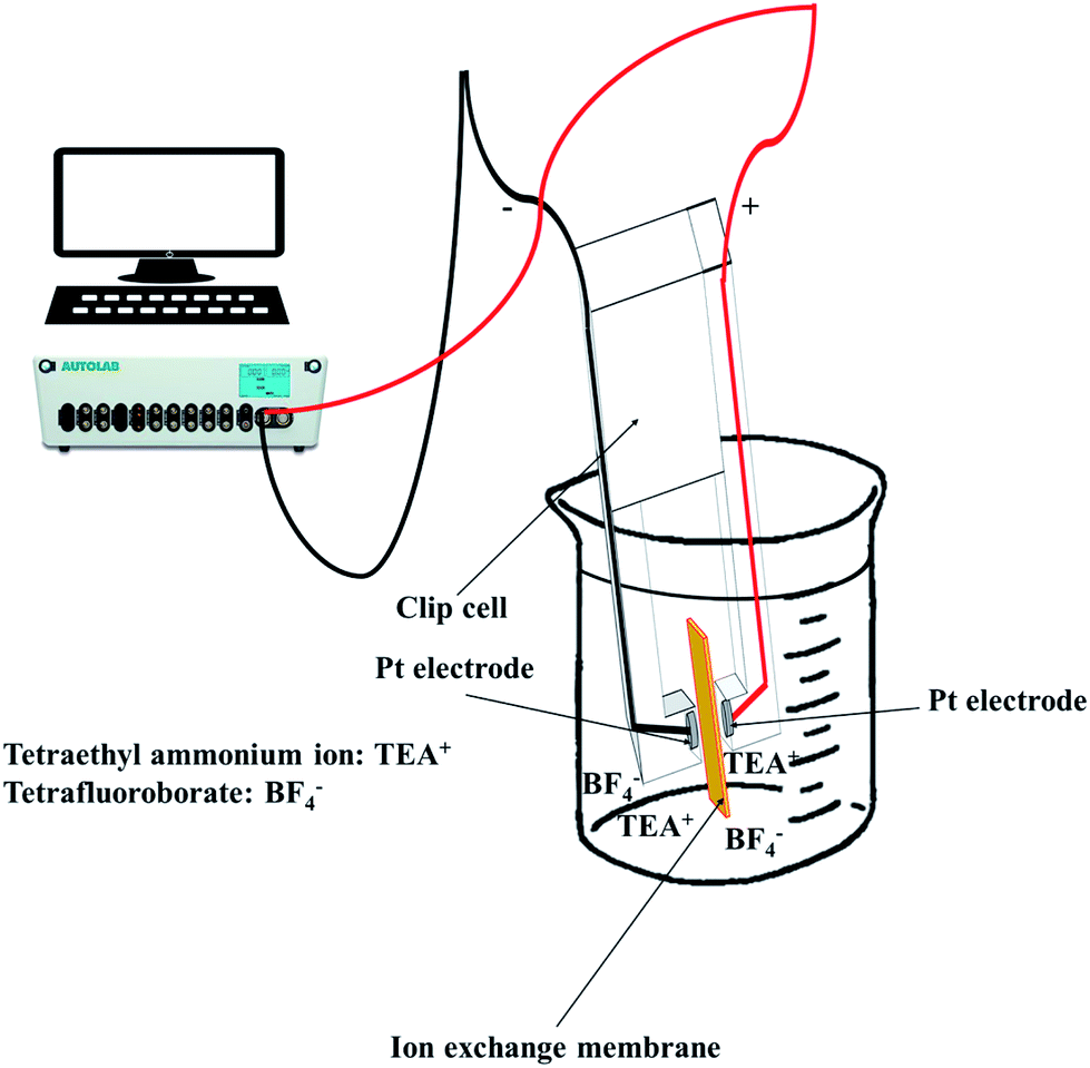 | ||
| Fig. 4 Measuring the through-plane conductivity using a clip cell. | ||
Meanwhile, the MER was estimated according to eqn (5).
| MER [Ω cm2] = (Rmemb − Rsol) × A | (5) |
The conductivity was calculated by eqn (6).
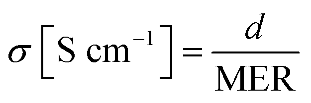 | (6) |
2.8 Preparation of the membrane for the scanning electron microscopy (SEM), atomic force microscopy (AFM), and X-ray diffraction (XRD) analysis
To observe the physical structure of the membranes on the micro-scale, the cross-section and surface of the samples were monitored with an electron microscope (Hitachi S-4700, Japan). For the investigation of the morphological change in the various fabricated membranes, samples of each, with a size of 2 × 2 cm2, were prepared. Each membrane was then immersed in DI water for one day to maintain a wet state. Topographic images of the samples were visualized using an AFM device (XE-100, PSIA Corp., Korea) equipped with a non-contact mode (non-contact tip: PPP-NCHR, Nanosensors). XRD analysis was measured using a Brunker D8 diffractometer (X'Pert Pro MPD, PANalytical, USA). Electrically aligned cQPPO membranes were fixed on sample-holder plates after the scan range was modulated from 5° to 30° to measure the XRD patterns.2.9 Operation of a single cell
To perform the charge/discharge experiment in a single cell, 40 mL of 0.05 M V(acac)3/1 M TEABF4 in ACN was used as the anolyte and catholyte solution. In the charge/discharge process, each electrolyte was continuously circulated at 60 mL min−1 from each reservoir to the cell. Also, the flow rate increased up to 120 mL min−1 to observe the change in the performance of the fabricated membrane in a single cell. The assembled NAVRFB system was operated using a battery cycler in a glove-box filled with argon to avoid water and oxygen contamination. The single cell performance was evaluated using a 5 × 5 cm2 effective membrane in the range of 1.6 and 2.8 V as the cut-off voltage. The carbon graphite and felt were introduced to react the reduction and oxidation, effectively.Fig. 5 illustrates the whole system operating the charge and discharge processes. In principle, reduction in a negative electrode should occur during the charge cycle. Conversely, the electrolyte of V(acac)3 was oxidized as a positive electrode. The oxidation and reduction half-reaction at each electrode can be rendered as eqn (7) and (8).
| Negative half-reaction: V(acac)3 + e− ↔ V(acac)3−, E0 = −1.72 V vs. Ag/Ag+ | (7) |
| Positive half-reaction: V(acac)3 ↔ V(acac)3+ + e−, E0 = 0.46 V vs. Ag/Ag+ | (8) |
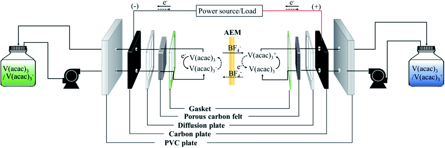 | ||
| Fig. 5 Diagram of the operating NAVRFB system; solid and dashed lines represent the charge/discharge process, respectively. | ||
Meanwhile, the current, voltage, and energy efficiency were calculated by eqn (9), (10), and (11), respectively.
 | (9) |
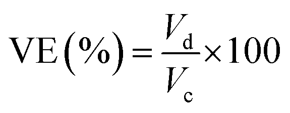 | (10) |
| EE (%) = CE × VE × 100 | (11) |
2.10 Measurement of vanadium permeability
Similar to the measurement of the transport number, the membrane was fixed in a closed two-compartment cell to avoid evaporation of the solvent. Each compartment was filled by 1 M TEABF4 with 0.5 mM V(acac)3 and 1 M TEABF4 in ACN of the same volume, respectively. For the AHA membrane, the vanadium concentration in the enrichment compartment was 0.1 M V(acac)3/1 M TEABF4 instead of 0.5 mM V(acac)3/1 M TEABF4 in ACN, because of the low permeability. A sample was taken from each compartment at 60 min intervals for 4 h. The diffusion coefficient was then estimated by measuring the absorbance of the sample at a wavelength of 298 nm, using a UV-vis spectrometer (Optizen 3220UV, Mecasys, South Korea).163. Results and discussion
3.1 Current profile, ion conductivity, and MER in the through-plane direction
The cQPPO structure was composed of the porous PTFE filled with the QPPO polymer. In particular, the QPPO polymer can be divided into two parts, which are the backbones of the aromatic region and dipole groups, as shown in Fig. 6. Because of their polarity, the electric energy can easily influence the dipole groups.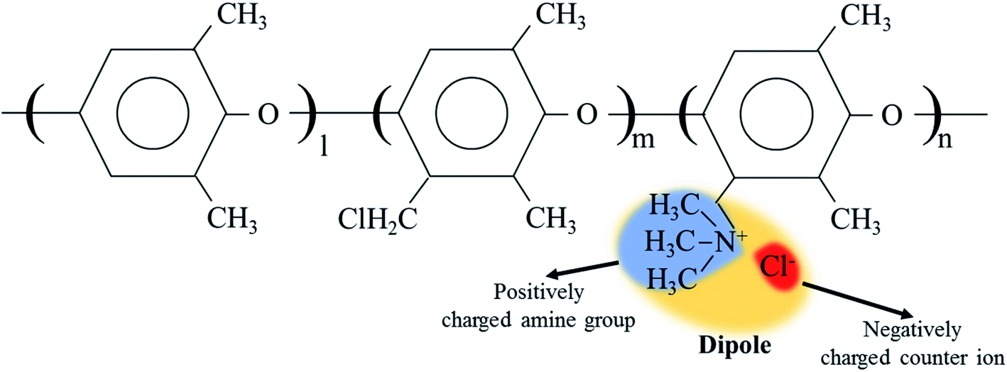 | ||
| Fig. 6 The dipole group containing the positively charged functional group and negatively charged ion in QPPO; the electric field can influence the dipole groups because of polarity. | ||
In a previous study, we observed the current change when preparing a QPPO membrane with electrical treatment because it indirectly predicts the degree of the aligned ion channels, as per eqn (12).21,24,25
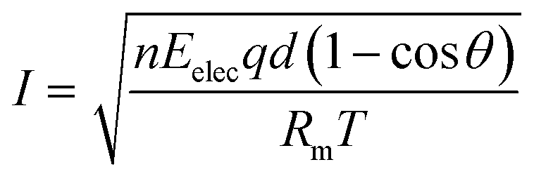 | (12) |
Based on eqn (12), we observed the current change during the fabrication process of the cQPPO membrane under various intensities of the electric field because it is a good parameter for estimating the behavior of ion channels indirectly. The current variation depends on the movement of the dipole groups as a specific angle under the electric field.
Fig. 7 shows the current changes during the fabrication time under different voltages in a through-plane direction. Initially, the current profile almost approached zero in line with the elapsed time because of the non-external potential (0 V). Significant slope changes were observed when electric fields of three conditions were applied between two casting blades. Thereafter, the current profiles converged to zero slopes in the applied voltage. These common phenomena of the current profiles were divided into three levels, as shown in Fig. 7(b). In the first step, the randomly entangled QPPO polymer reacted rapidly in the powerful current because a large number of dipole groups in the QPPO immediately started to move in the direction of the applied electrical energy. In the second step, most of the ion channels were oriented in the specific direction of the electric field. In this state, the only reduced current slope was observed, because a few ion channels were still arranged under the external electric field. In the final step, the movement of ion channels subsided because they were almost aligned in the direction of the electric field. Hence, the current changes were not observed, although the external energy was constantly supplied in the ion channels. The peak currents of the cQPPO membranes were relatively low compared with the previous study, although the electrical intensities supplied were almost the same.21 In cQPPO membranes, the non-charged porous PTFE must be densely filled with the QPPO polymer. Its amounts were relatively limited in the dimensionally effective volume compared with the pure QPPO membrane. Accordingly, the current intensity was reduced because it depended on the number of dipole groups in the same electric field. We avoided delivering extremely high potentials, which can cause viscous changes in the QPPO solution, with solvent electrolysis between the metal blades.
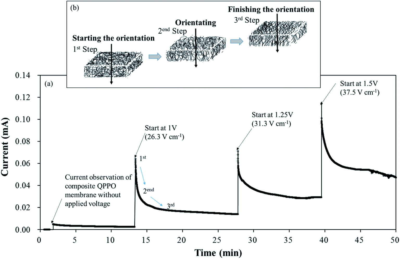 | ||
| Fig. 7 Effect of the electrical treatment on cQPPO: (a) graph of the current changes according to the elapsed time under a different potential; (b) degree of the alignment with the elapsed time during the fabrication process using an electric field and going in a through-plane direction. | ||
In order to improve the ion conductivity for IEMs, a simple method may be to increase the number of functional groups (or IECs), because the probability of the transferred ions depends on the number of ion channels.26 Practically, the large number of functional groups must be restricted, because extremely high IEC leads to deterioration of the chemical and mechanical stabilities of IEMs. On the other hand, electrically treated cQPPO membrane improves conductivity by rapid ion transport through the ion channels without compromising its mechanical and chemical properties.
Fig. 8(a) shows the relation between the IEC and the through-plane conductivity of the electrically treated cQPPO membrane. The widely used commercial AHA membrane exhibited the lowest conductivity and IEC when compared with the fabricated membranes. It could be attributed to its inherent yet unknown chemical and morphological structure. In addition, the commercial AHA membrane is only optimized in aqueous systems containing chloride or sulfate ions. The IEC values of the electrically treated membrane showed constant regardless of the applied intensity of the electric field. Although, the conductivity of the cQPPO membrane was clearly improved in accordance with the applied intensity of the electric field, implying that increased aligned ion channels in through-plane direction could effectively transfer the charge carriers of BF4−. Electrically treated cQPPO membranes were observed as the constant IEC values regardless of the applied electric field. In addition, IECs of cQPPO membranes were commonly reduced as compared with the QPPO membrane because the non-charged groups of the PTFE were contained in an effective volume. As seen in Fig. 8(b), the effect of the electric treatment was also revealed at MER. In general, MER depends on the membrane thickness, which is an excellent strategy to improve the performance of electrical devices. It was possible to fabricate the cQPPO membranes as a thin film, which led to a significantly reduced MER. Besides, the effect of the aligned ion channels in the cQPPO membrane contributed to reducing the MER value, which showed a maximum 347-fold difference compared with the AHA membrane. The ion conductivity and MER of the QPPO membrane could not be obtained because of partial decomposition. These distinct differences between the QPPO and cQPPO membrane were attributed to dimensional stabilities, as discussed below.
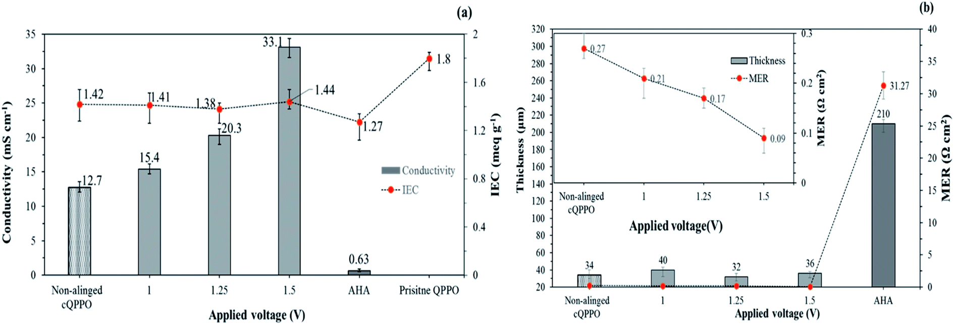 | ||
| Fig. 8 (a) Ion exchange capacity and through-plane conductivity for fabricated membranes according to the intensity of the electrical treatment and AHA in 1 M TEABF4 in ACN; (b) comparison of the MER of fabricated membranes and commercial AHA membrane. | ||
3.2 Dimensional stabilities and transport number
To apply electrical systems, the swelling ratio and solvent uptake are essential factors to determine the best IEMs. Suitably swollen IEMs in the electrolyte accelerate ion transfer through the ion channels. The use of this kind of membrane increases ionic conductivity, as is known from the vehicle and Grotthuss-type theory.27–29 However, extremely poor dimensional stabilities or solvent resistances can cause not only IEMS dissolving in the electrolyte but also decreased ion selectivity (or transport number), with ion crossover through the ion channel of the polymer electrolyte.30,31One of the merits of composite IEMs is the improved dimensional or mechanical strength compared with casting IEMs. In this study, fabricated membranes were able to improve dimensional stabilities as well.
As presented in Fig. 9, the AHA membrane showed high dimensional stability in the IEMs, whereas the polymeric QPPO membrane showed poor dimensional stability in the ACN solvent. Its severely high solvent absorption caused tearing the QPPO membrane. The dimensional stability of the cQPPO membranes was remarkably improved, irrespective of applied electric fields. This positive effect was revealed by measuring the solvent absorption of the porous PTFE. Owing to the excellent chemical and mechanical stability, the PTFE showed the lowest solvent absorption. Its substrate can effectively curb swelling in the QPPO polymer under the ACN solvent. In our previous study, the solvent uptake of the casting membranes tended to increase according to the intensity of the electric field.21,32 However, the ACN uptake of the cQPPO membranes was almost constant regardless of applied electric fields.
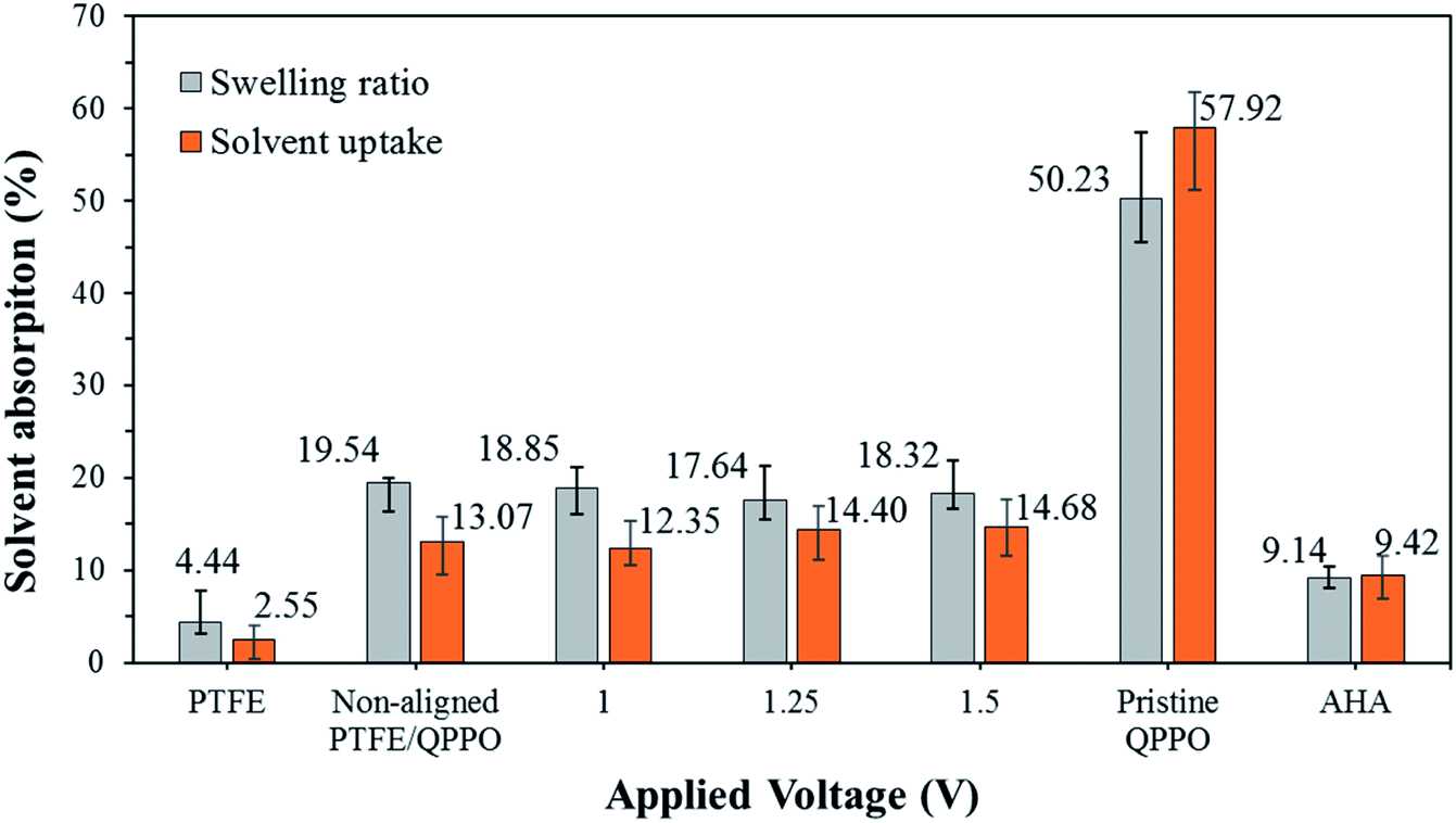 | ||
| Fig. 9 Swelling ratio and solvent uptake for the fabricated membranes in ACN, according to the intensity of the electrical treatment. | ||
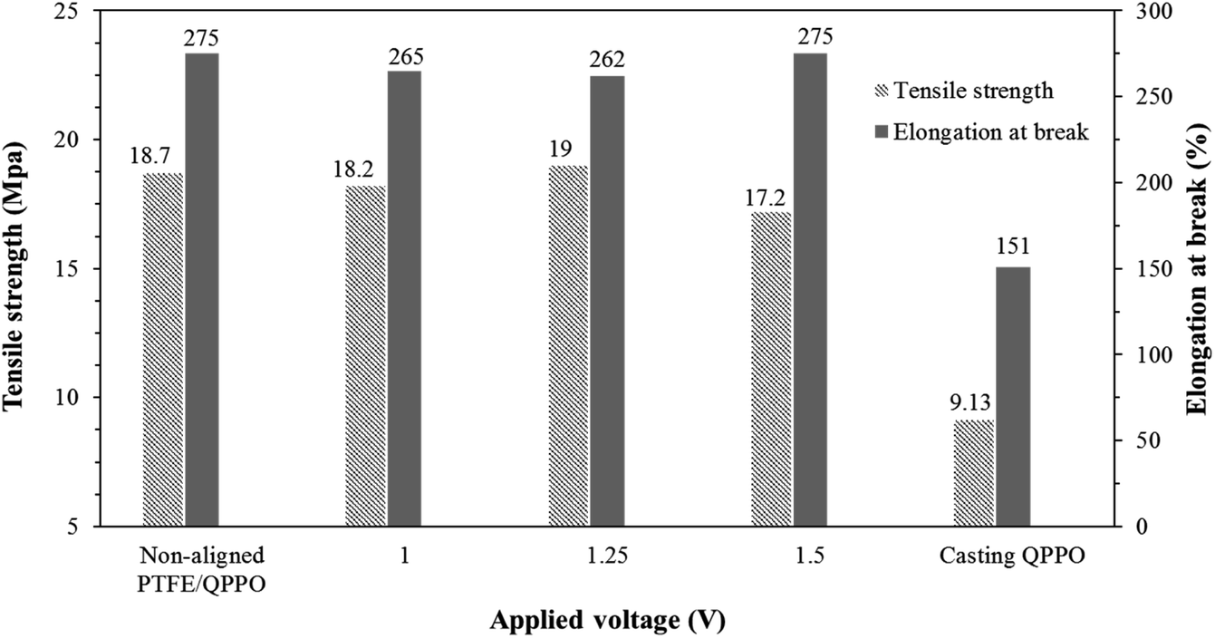
The tensile strength and capacity for elongation are significant parameters in the membrane. In RFB systems, IEMs must endure a pressure drop because of the high flow rate.33 Fig. 10 shows the effects of the substrate PTFE by comparing the cQPPO membranes and the polymeric QPPO membrane.
 | ||
| Fig. 10 Tensile strength and elongation at break for fabricated membranes in accordance with the applied electrical treatment. | ||
The tensile strength and elongation property of the fabricated membranes were intimately related to their solvent absorption. The original QPPO membrane was measured as having the lowest tensile strength and elongation at break. However, all fabricated cQPPO membranes were clearly improved in terms of mechanical stabilities, owing to the reinforcing effect of the substrate.34 It imply that tensile strength and elongation property of the membranes depends on the PTFE substrate used regardless of the alignment degree.
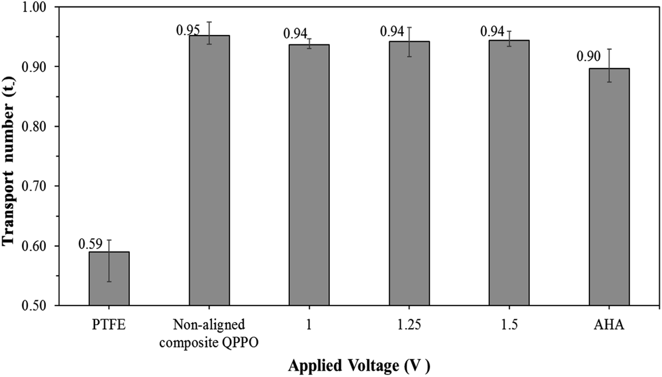
Most of the IEMs consist of the main backbone and charged functional groups, which can selectively transfer the counter-ions. The transport number is an indicator by which to estimate the degree of perm-ion selectivity for the IEMs. To maintain electroneutrality in RFB systems, the AEMs must carry out the transfer of the BF4− ions to maintain electroneutrality, which can lead to improved performance.
The transport number of the fabricated membranes examined, as seen in Fig. 11. Ion selectivity of PTFE was hardly observed, owing to the absence of positively charged groups (or functional groups) to attract the anions. Thus, cations and anions in the electrolyte can freely permeate through the PTFE. As described above, the transport number for the QPPO membrane was difficult to obtain because its poor dimensional properties caused its destruction in the presence of electrolytes. The AHA and cQPPO membranes showed sufficient anion selectivity with the high ion transport numbers.
 | ||
| Fig. 11 Transport number for AHA and the fabricated membranes in relation to the applied voltage. | ||
3.3 Morphological and crystalline changes in oriented cQPPOs
Based on the pore-filling method, the QPPO polymer must be densely packed into the porous PTFE. In particular, the morphological changes in the fabricated membranes were observed from the photographs and SEM images as shown in Fig. 12(a) and (b).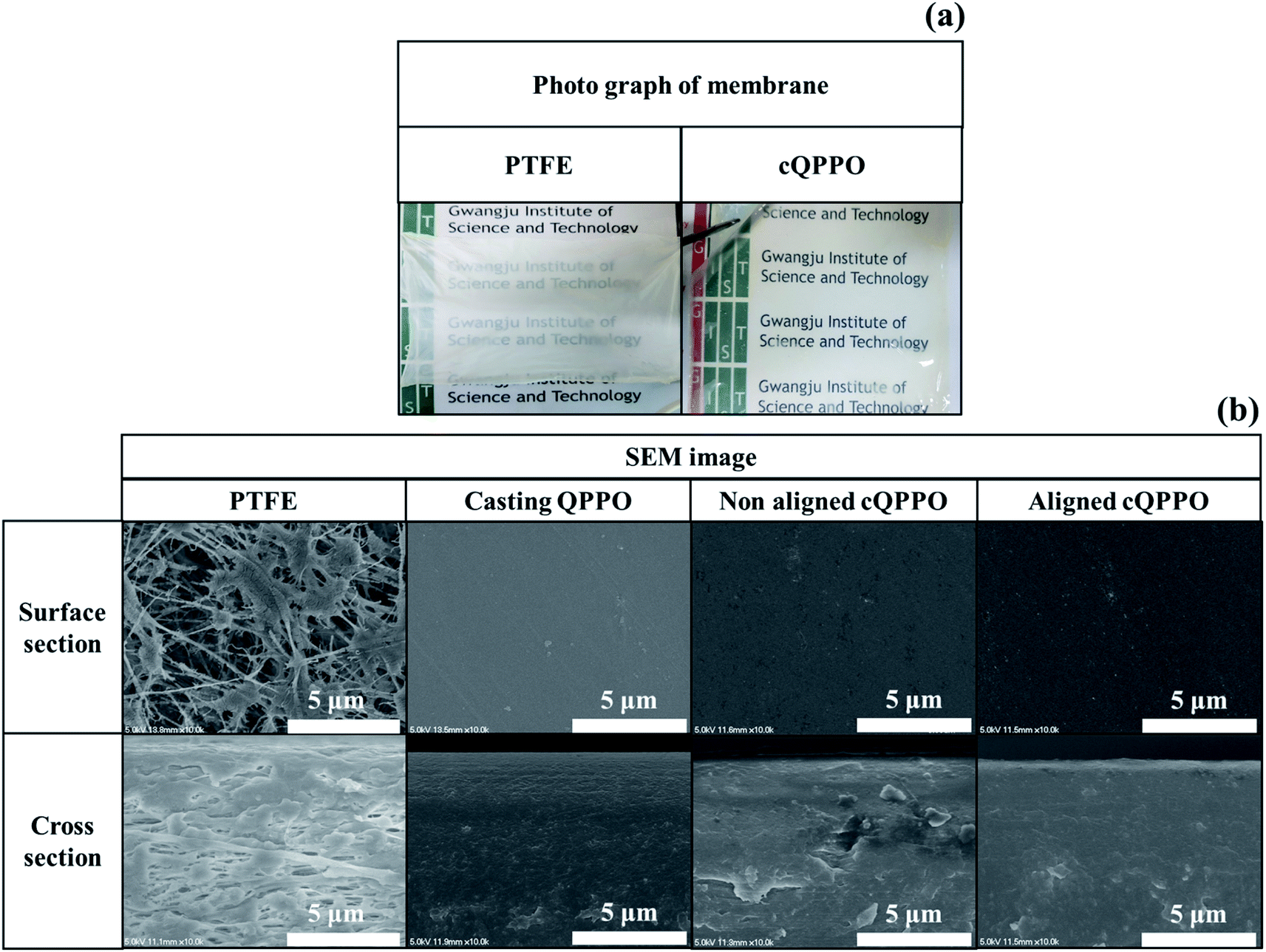 | ||
| Fig. 12 (a) Photographs of the porous substrate and cQPPO; (b) comparison of the SEM images in porous PTFE, casting QPPO, cQPPO with no electrical treatment, and aligned cQPPO at 1.5 V. | ||
The cQPPO membrane of the photograph was relatively transparent, because the refractive index of the polymer electrolyte was similar to the QPPO polymer in the substrate. Thus, the scattering of visible light was reduced through the pores.35 In the SEM images, the morphological changes were clearly observed, demonstrating that the PTFE existed in the empty spaces on the micro-scale. The fabricated cQPPO membranes showed that the QPPO polymers were densely impregnated in the porous PTFE. The morphological structure of this kind of pore-filled membrane was similar to that of the casting QPPO membrane, although non-oriented and oriented cQPPOs were not clearly observed as a morphological change on the SEM image.
Ran et al. reported that ion channels of QPPO are aggregated at the nano level.36 To compare the morphological changes, the non-aligned cQPPO and aligned cQPPO membrane were visualized using AFM on the nano-scale, as presented in Fig. 13.
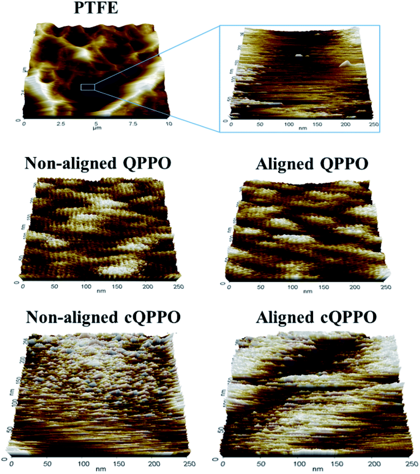 | ||
| Fig. 13 Morphological AFM image of fabricated membranes: (a) the porous PTFE; (b) empty space of porous substrate; (c) casting QPPO; (d) aligned QPPO at 31 V cm−1; (e) non-aligned and (f) Aligned cQPPO at 1.5 V (about 31 V cm−1). | ||
At first, the AFM image of porous PTFE showed a pattern similar to the SEM image of the PTFE.37 The morphological structure of the PTFE was clear in the nano-scale because of the empty pore. Previously, we reported that ion channels in a casting QPPO membrane were affected by an electric field.21 The oriented ion channels in the casting QPPO membrane were regularly arranged, with a constant distance between them, compared with the ion channels in a pristine QPPO membrane. The AFM images of the fabricated cQPPO membranes were observed as a different morphological structure. In the non-electrically treated cQPPO membranes, the ion channels of the QPPO polymer were densely aggregated in the limited pore size (0.45 μm) of PTFE. On the other hand, ion clusters of the electrically treated cQPPO membrane were regularly arranged in a restricted area of the porous PTFE.
We investigated another evidence for the morphological change in the aligned cQPPO membrane by measuring the XRD. As presented in Fig. 14(a), the high peak of the porous substrate appeared at approximately 18°, which indicates the presence of a PTFE matrix.38 Broad peaks were observed at around 15° and 21° in the casting QPPO membrane, which consisted of amorphous and crystalline regions (Fig. 14(b)). Accordingly, the cQPPO membranes commonly showed combined peaks at both the PTFE and QPPO membrane as seen in Fig. 14(c). In most membranes of PPO types, the peak intensity at around 15° generally decreases with increased functional groups, because the IEC values influence the amorphous region.39–41 The peak intensity (15°) of the aligned cQPPO membranes increased according to the applied intensity of the electric field, as shown in Fig. 14(d), although their IECs were constant values. This phenomenon implied that the ion channels of the QPPO polymer were slightly aligned in a through-plane direction with increased crystallinity because of the movement of the dipoles in the QPPO polymer under an electric field.42
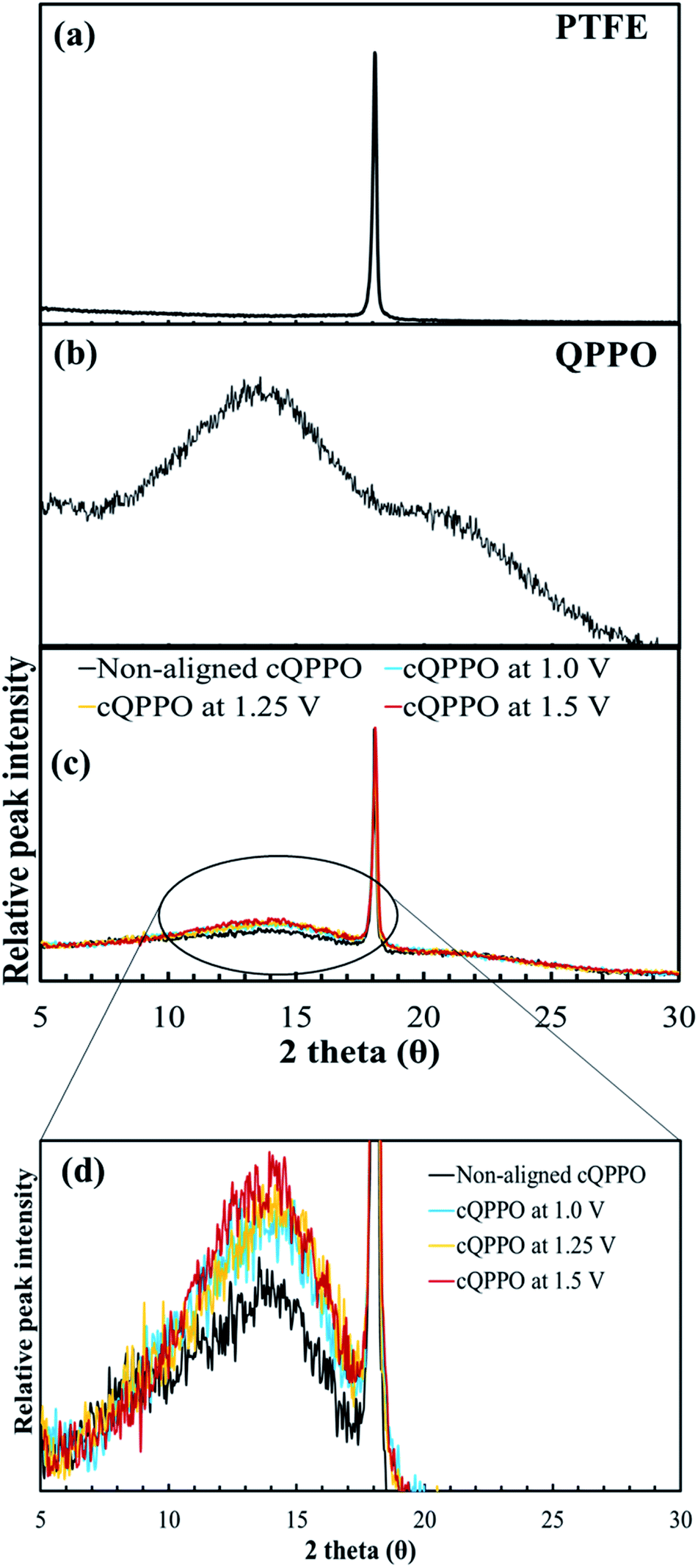 | ||
| Fig. 14 XRD patterns: (a) the porous PTFE, (b) QPPO membrane and (c) cQPPO membranes; (d) comparison of peak intensity according to applied intensity of the electric field. | ||
3.4 Performance of a NAVRFB and vanadium permeability
In most of aqueous VRFBs, prevention of the ion cross-mixing have been studied to increase the long-life cycle so that their systems may be enough in terms of high electrical power and current density to utilize the large-scale applications.43–45 Meanwhile, a drawback of the NABRFBs is low operating current density with reduced VE resulting from the low conductivity of charge carriers and solubility of redox electrolytes. To overcome these problems with operation of the NAVRFBs at a high operating current density, the IEM must have low electrical resistance.43 In this section, the non-aligned and the aligned cQPPO membrane of the highest conductivity were tested in 0.05 M V(acac)3/1 M TEABF4 in a single cell to observe the effect of aligned ion channels. The commercial AHA membrane was also applied in a single cell as a reference membrane.As seen in Fig. 15(a) and (b), the charge/discharge capacity of the aligned cQPPO membrane was higher than that of the non-aligned cQPPO membrane. The capacity difference between the non-aligned and the aligned cQPPO membrane was clearly observed, owing to the growing ohmic resistance and overpotential at a high current density.16 Therefore, the aligned cQPPO membrane was associated with relatively high ionic conductivity, causing reduced ohmic polarization of the batteries. This result led to improving the VE, and its value showed a prominent difference as current density increased, as presented in Fig. 15(c) and (d). The CE of the NAVRFB assembled with all fabricated membranes increased with the rising current density. This tendency can be attributed to the reduced crossover of the redox electrolyte in the short period of the charge/discharge at a high current density.46 CE of the non-aligned cQPPO membrane was higher than that of the aligned cQPPO membrane at both 20 and 40 mA cm−2, implying that the degree of ion crossover of aligned cQPPO membrane is slightly higher than that of the non-aligned cQPPO membrane. However, the charge/discharge operation of the non-aligned cQPPO membrane was impossible at a higher current density than 40 mA cm−2 in a single cell.
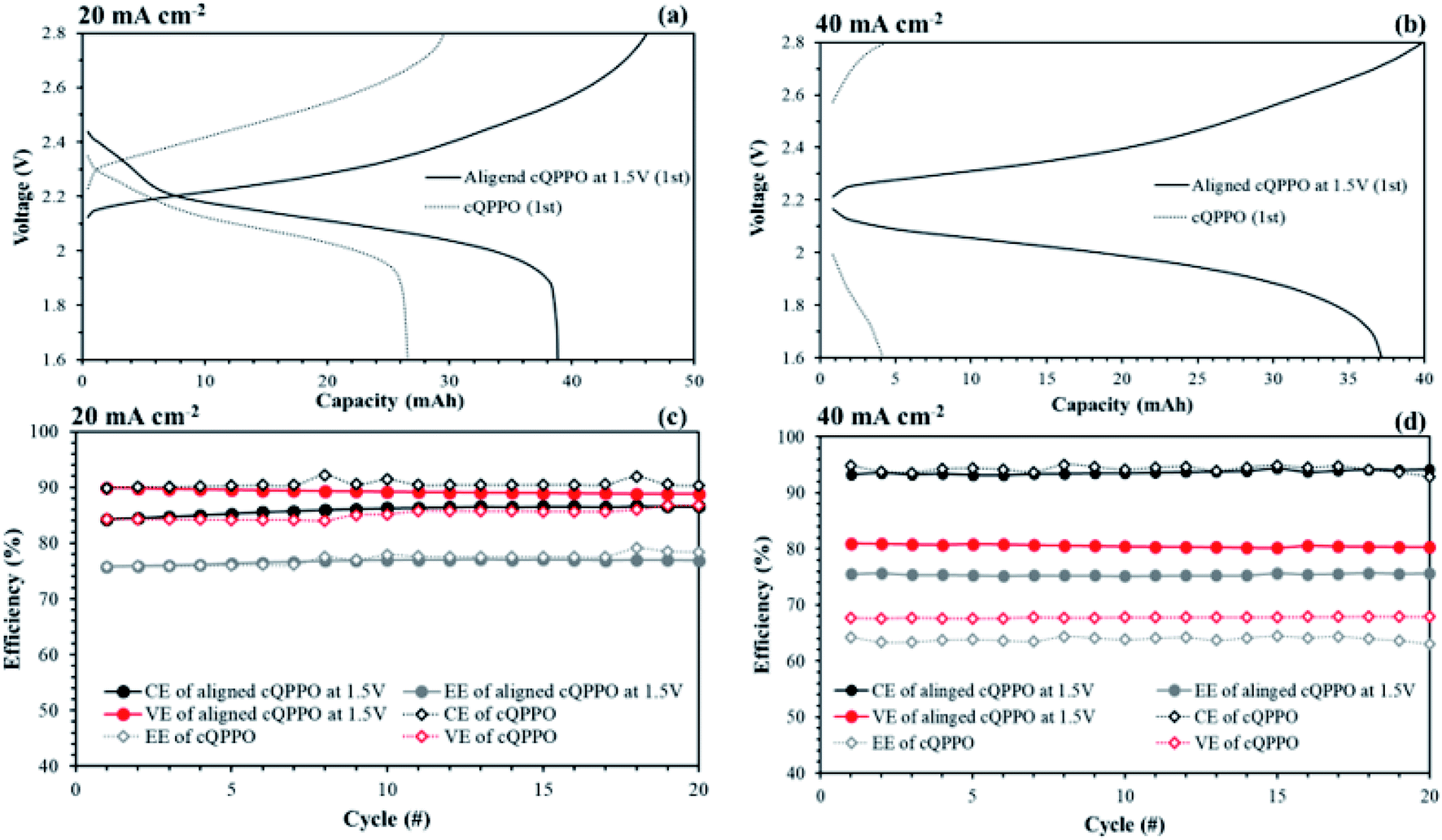 | ||
| Fig. 15 Comparison of performances in a single cell using 0.05 M V(acac)3/TEABF4 at 60 mL min−1: (a) charge/discharge curves at (a) 20 and (b) 40 mA cm−2; efficiencies at (c) 20 and (d) 40 mA cm−2 by applying the non-aligned and aligned cQPPO membrane. | ||
The aligned cQPPO in a single cell could be operated at even higher current density because of its low MER. To compare the performance between the aligned cQPPO and AHA membrane, we observed the charge/discharge operation, as presented in Fig. 16. Basically, the NAVRFB incorporated with AHA membrane was operated at an insufficient current density of 1 mA cm−2 only because of the high MER (see Fig. 16(a) and (b)), although efficiencies were stably maintained as reasonable values. The NAVRFB assembled with aligned cQPPO membrane could be operated at a high current density of 80 mA cm−2. In particular, the charge/discharge capacity of the aligned cQPPO membrane was still higher than that of the AHA membrane, as seen in Fig. 16(c).
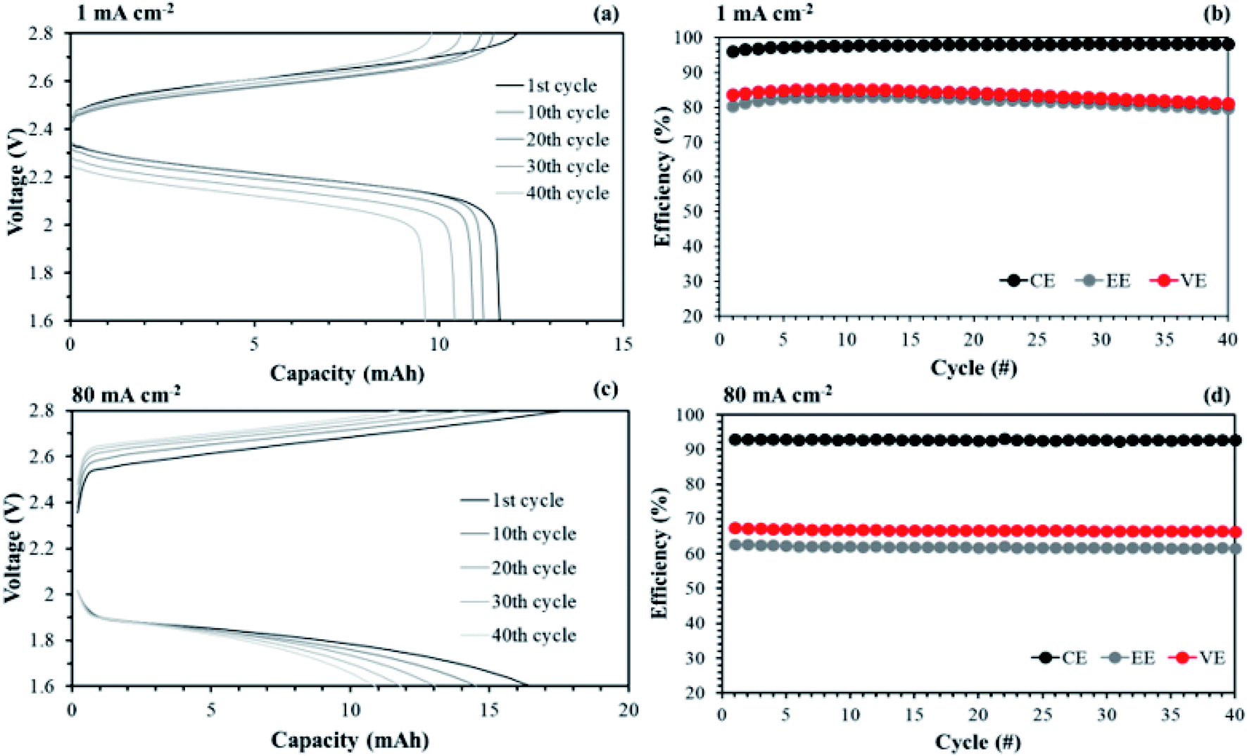 | ||
| Fig. 16 Comparison of performances in a single cell using 0.05 M V(acac)3/TEABF4 at 60 mL min−1: (a) charge/discharge curves and (b) efficiencies by applying AHA membrane; (c) charge/discharge curves and (b) efficiencies by introducing the aligned cQPPO membrane at 1.5 V. | ||
The efficiencies of the aligned cQPPO membrane were almost constant, although the percentage values were reduced according to the increased high current density, as shown in Fig. 16(d).
Another advantage of the membrane fabricated in this study is its high mechanical stability owing to the reinforced substrate even at 35 μm thickness. In RFB systems, the high flow rate of redox electrolytes may induce a pressure drop across the membrane. Therefore, the IEMs must be able to endure a high flow rate without destruction. Fig. 17 shows performance curves of the single cell test, applying the aligned cQPPO at an increased flow rate.
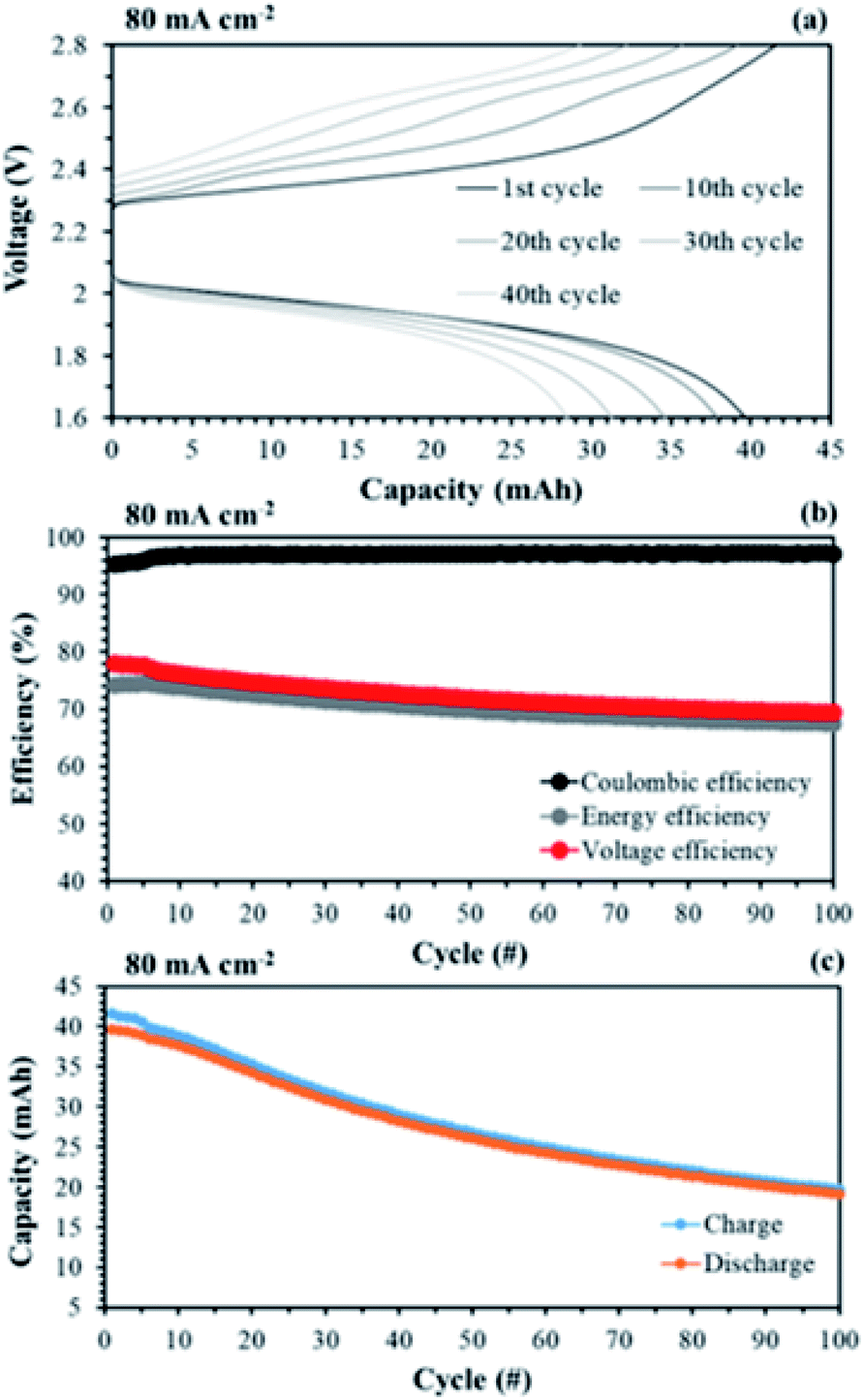 | ||
| Fig. 17 Performances of a single cell with 0.05 M V(acac)3/1 M TEABF4 at a high flow rate (120 mL min−1): (a) capacity–voltage curves; (b) efficiencies and (d) capacity changes of long-term operation, by applying the aligned cQPPO at 1.5 V. | ||
As shown in Fig. 17(a), the charge/discharge capacity of the aligned cQPPO was improved by as much as 2.3-fold at an increased flow rate of 120 mL min−1 compared with that of 60 mL min−1. The CE, EE, and VE were also improved, rising to 97.1, 70.3, and 72.5% during 100 cycles, respectively (see Fig. 17(b)). This is attributed to the fact that the high flow rate increases the local electrolyte velocity with reduced loss of concentration polarization in the electrode. Thus, the cells could achieve higher voltages at a high flow rate.47 The charge/discharge capacity decreased with the elapsed cycle, as seen in Fig. 17(c). The capacity loss is generally related to the ion crossover, which depends on the diffusion coefficient of the redox couples in the membrane.
The single cell test for the aligned cQPPO membrane was stably conducted above a high current density of 80 mA cm−2, although the charge/discharge capacities were reduced.
Hinkle et al. reported that redox electrolyte of V(acac)3 can be dissolved up to about 0.2 M in 1 M TEABF4 without precipitation.48 The redox electrolyte concentration may be able to improve the capacity at a high current density. As seen in Fig. 18(a), the NAVRFB assembled with the aligned cQPPO membrane was smoothly operated with enhanced charge/discharge capacities in an increased concentration. Furthermore, the CE values were continuously maintained at more than 90% during 40 cycles.
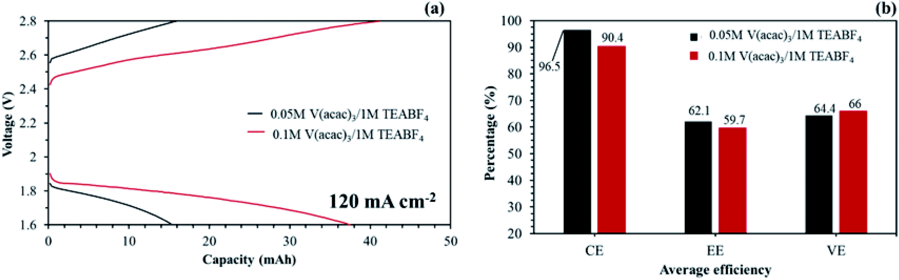 | ||
| Fig. 18 Single cell performances on the application of the aligned cQPPO at 120 mA cm−2 with 120 mL min−1: (a) capacity–voltage curves of the NAVRFB assembled with the aligned cQPPO membrane; (b) average efficiencies in 40 cycles. | ||
The diffusion coefficient of the vanadium species in the membrane can be calculated by eqn (13).49
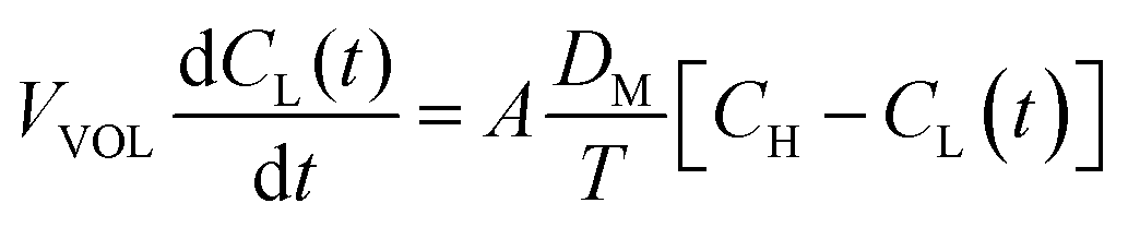 | (13) |
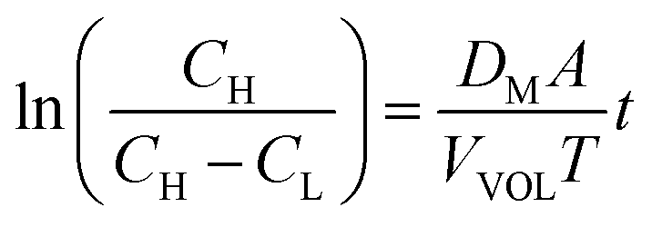 | (14) |
The measured value of the left side of eqn (14) can not only predict the relative degree of the vanadium permeability but also calculate the diffusion coefficient in the membrane.
As presented in Fig. 19, the permeability of the aligned cQPPO membrane was slightly higher than that of the cQPPO membrane. We believe that the vanadium complex can easily permeate through the straight-stretched ion channels, although vanadium species have a bulky and heavy structure.14 The frequently used AHA membrane was observed as having the lowest degree of permeability, which influenced the diffusion coefficient, as listed in Table 3.
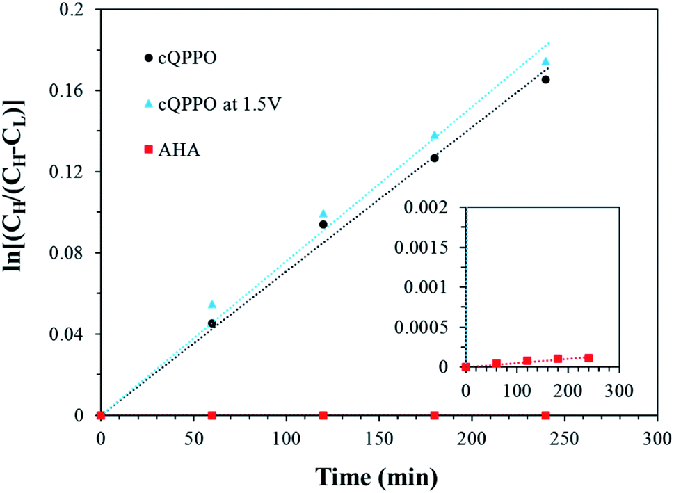 | ||
| Fig. 19 Comparison of the concentration changes in V(acac)3 on the deficient side with the elapsed time for the three types of membranes. | ||
| Membrane type | Diffusion coefficient (cm2 s−1) |
|---|---|
| cQPPO | 3.18 × 10⁻⁶ |
| cQPPO at 1.5 V | 3.47 × 10⁻⁶ |
| AHA | 2.05 × 10⁻⁹ |
The diffusion coefficient of fabricated membranes was higher than that of the AHA membrane, owing to the membrane thickness.17 However, the NAVRFB assembled with fabricated membrane could successfully operate at a high current density of 120 mA cm−2.
4. Conclusion
In this study, cQPPO membranes were fabricated by the orientation of ion channels of the QPPO polymer in the PTFE under the applied electric field. The fabricated aligned cQPPO membranes showed high anion perm-selectivity, enhanced dimensional stabilities, low MER and high ionic conductivity. Especially, the high conductivity was accomplished by the orientated ion channels which have the ability to rapidly migrate without tortuous ion-pathway. The morphological change of aligned ion channels was verified by the AFM image and XRD analysis. The optimized membrane was evaluated in NAVRFB and its performance was compared with commercial AHA membrane. The AHA membrane was operated at 1 mA cm−2 and the aligned cQPPO membrane showed potential to operate 120 mA cm−2 and higher. Moreover, the aligned membrane showed an average CE of 97.1%, EE of 69.3% and VE of 71.3% at 80 mA cm−2. In this study, the AEM was optimized for applications in the non-aqueous solutions of a RFB. However, the discharge capacity decay was observed through the unknown degradation mechanism which requires further study.Conflicts of interest
There are no conflicts to declare.Acknowledgements
This work was supported by the National Research Foundation of Korea Grant by the Korean Government (MISP) (NRF-2001-C1AAA01-0030538) and partly by Korea Institute of Energy Research (KIER) (BP-5506), Gwangju, South Korea.References
- L. H. Thaller, US Patent 3996064, 1976.
- T. Yamamura, Y. Shiokawa, H. Yamana and H. Moriyama, Electrochim. Acta, 2002, 48, 43–50 CrossRef CAS.
- Q. Liu, A. E. S. Sleightholme, A. A. Shinkle, Y. Li and L. T. Thompson, Electrochem. Commun., 2009, 11, 2312–2315 CrossRef CAS.
- A. A. Shinkle, A. E. S. Sleightholme, L. D. Griffith, L. T. Thompson and C. W. Monroe, J. Power Sources, 2012, 206, 490–496 CrossRef CAS.
- Q. Liu, A. A. Shinkle, Y. Li, C. W. Monroe, L. T. Thompson and A. E. S. Sleightholme, Electrochem. Commun., 2010, 12, 1634–1637 CrossRef CAS.
- A. E. S. Sleightholme, A. A. Shinkle, Q. Liu, Y. Li, C. W. Monroe and L. T. Thompson, J. Power Sources, 2011, 196, 5742–5745 CrossRef CAS.
- D. Zhang, H. Lan and Y. Li, J. Power Sources, 2012, 217, 199–203 CrossRef CAS.
- W. Wang, Q. Luo, B. Li, X. Wei, L. Li and Z. Yang, Adv. Funct. Mater., 2013, 23, 970–986 CrossRef CAS.
- H. Majima, E. Peters, Y. Awakura and S. K. Park, Metall. Trans. B, 1987, 18, 41–47 CrossRef.
- R. Holze, in Electrochemistry, Springer, 2016, pp. 1595–1595 Search PubMed.
- L. Coury, Curr. Sep., 1999, 18, 91–96 CAS.
- K. Gong, Q. Fang, S. Gu, S. F. Y. Li and Y. Yan, Energy Environ. Sci., 2015, 8, 3515–3530 RSC.
- I. L. Escalante-García, J. S. Wainright, L. T. Thompson and R. F. Savinell, J. Electrochem. Soc., 2015, 162, A363–A372 CrossRef.
- S.-H. Shin, S.-H. Yun and S.-H. Moon, RSC Adv., 2013, 3, 9095–9116 RSC.
- S. Maurya, S.-H. Shin, K.-W. Sung and S.-H. Moon, J. Power Sources, 2014, 255, 325–334 CrossRef CAS.
- S.-H. Shin, Y. Kim, S.-H. Yun, S. Maurya and S.-H. Moon, J. Power Sources, 2015, 296, 245–254 CrossRef CAS.
- S.-J. Gong, D. Kim, E. Cho, S. S. Hwang and J. Won, ChemistrySelect, 2017, 2, 1843–1849 CrossRef CAS.
- T. Yamaguchi, H. Zhou, S. Nakazawa and N. Hara, Adv. Mater., 2007, 19, 592–596 CrossRef CAS.
- T. Yamaguchi, F. Miyata and S.-i. Nakao, J. Membr. Sci., 2003, 214, 283–292 CrossRef CAS.
- T. Yamaguchi, F. Miyata and S. Nakao, Adv. Mater., 2003, 15, 1198–1201 CrossRef CAS.
- J.-H. Kim, S. Ryu, J.-Y. Lee and S.-H. Moon, J. Membr. Sci., 2018, 553, 82–89 CrossRef CAS.
- H. Strathmann, A. Grabowski and G. Eigenberger, Ind. Eng. Chem. Res., 2013, 52, 10364–10379 CrossRef CAS.
- S.-H. Yun, S.-H. Oh, J.-J. Woo, J.-Y. Lee, J.-H. Lee, S.-B. Lee, C.-M. Min, J. Lee, J.-S. Lee and S.-H. Moon, RSC Adv., 2013, 3, 24154–24162 RSC.
- T. Manaka, D. Shimura and M. Iwamoto, Chem. Phys. Lett., 2002, 355, 164–168 CrossRef CAS.
- M. Iwamoto, Y. Majima, H. Naruse, T. Noguchi and H. Fuwa, Nature, 1991, 353, 645–647 CrossRef CAS.
- X. Ye, H. Bai and W. S. W. Ho, J. Membr. Sci., 2006, 279, 570–577 CrossRef CAS.
- K. N. Grew and W. K. S. Chiu, J. Electrochem. Soc., 2010, 157, B327–B337 CrossRef CAS.
- P. Choi, N. H. Jalani and R. Datta, J. Electrochem. Soc., 2005, 152, E84–E89 CrossRef CAS.
- S.-J. Seo, B.-C. Kim, K.-W. Sung, J. Shim, J.-D. Jeon, K.-H. Shin, S.-H. Shin, S.-H. Yun, J.-Y. Lee and S.-H. Moon, J. Membr. Sci., 2013, 428, 17–23 CrossRef CAS.
- W. Wei, H. Zhang, X. Li, Z. Mai and H. Zhang, J. Power Sources, 2012, 208, 421–425 CrossRef CAS.
- N. Tanaka, M. Nagase and M. Higa, J. Membr. Sci., 2011, 384, 27–36 CrossRef CAS.
- J.-Y. Lee, J.-H. Lee, S. Ryu, S.-H. Yun and S.-H. Moon, J. Membr. Sci., 2015, 478, 19–24 CrossRef CAS.
- A. Tang, J. Bao and M. Skyllas-Kazacos, J. Power Sources, 2011, 196, 10737–10747 CrossRef CAS.
- Y. Zhao, J. Pan, H. Yu, D. Yang, J. Li, L. Zhuang, Z. Shao and B. Yi, Int. J. Hydrogen Energy, 2013, 38, 1983–1987 CrossRef CAS.
- H. Jung, K. Fujii, T. Tamaki, H. Ohashi, T. Ito and T. Yamaguchi, J. Membr. Sci., 2011, 373, 107–111 CrossRef CAS.
- J. Ran, C. Fu, L. Ding, P. Cao and T. Xu, J. Mater. Chem. A, 2018, 6, 5714–5723 RSC.
- M. M. A. Shirazi, A. Kargari and M. Tabatabaei, Chem. Eng. Process., 2014, 76, 16–25 CrossRef CAS.
- T. Y. Guo, Q. H. Zeng, C. H. Zhao, Q. L. Liu, A. M. Zhu and I. Broadwell, J. Membr. Sci., 2011, 371, 268–275 CrossRef CAS.
- S. Yang, C. Gong, R. Guan, H. Zou and H. Dai, Polym. Adv. Technol., 2006, 17, 360–365 CrossRef CAS.
- C. Li, J. Liu, R. Guan, P. Zhang and Q. Zhang, J. Membr. Sci., 2007, 287, 180–186 CrossRef CAS.
- C. Wang, Y. Huang, G. Cong, G. Lin and S. Zhao, J. Appl. Polym. Sci., 1997, 63, 559–563 CrossRef CAS.
- G. Distefano, H. Suzuki, M. Tsujimoto, S. Isoda, S. Bracco, A. Comotti, P. Sozzani, T. Uemura and S. Kitagawa, Nat. Chem., 2013, 5, 335 CrossRef CAS.
- X. Li, H. Zhang, Z. Mai, H. Zhang and I. Vankelecom, Energy Environ. Sci., 2011, 4, 1147–1160 RSC.
- A. Parasuraman, T. M. Lim, C. Menictas and M. Skyllas-Kazacos, Electrochim. Acta, 2013, 101, 27–40 CrossRef CAS.
- P. Zhao, H. Zhang, H. Zhou, J. Chen, S. Gao and B. Yi, J. Power Sources, 2006, 162, 1416–1420 CrossRef CAS.
- H. Zhang, H. Zhang, X. Li, Z. Mai and J. Zhang, Energy Environ. Sci., 2011, 4, 1676–1679 RSC.
- S. Maurya, P. T. Nguyen, Y. S. Kim, Q. Kang and R. Mukundan, J. Power Sources, 2018, 404, 20–27 CrossRef CAS.
- A. A. Shinkle, T. J. Pomaville, A. E. S. Sleightholme, L. T. Thompson and C. W. Monroe, J. Power Sources, 2014, 248, 1299–1305 CrossRef CAS.
- X. Luo, Z. Lu, J. Xi, Z. Wu, W. Zhu, L. Chen and X. Qiu, J. Phys. Chem. B, 2005, 109, 20310–20314 CrossRef CAS.
- P. K. Leung, Q. Xu, T. S. Zhao, L. Zeng and C. Zhang, Electrochim. Acta, 2013, 105, 584–592 CrossRef CAS.
| This journal is © The Royal Society of Chemistry 2020 |