Open Access Article
This Open Access Article is licensed under a Creative Commons Attribution-Non Commercial 3.0 Unported Licence

The preparation of a modified PVDF hollow fiber membrane by coating with multiwalled carbon nanotubes for high antifouling performance

MengJing Caoa, Yan Zhang*a, BoKang Zhangc, ZiQi Liub, XiangShan Mab and ChangMing Chena
aKey Laboratory of Beijing for Water Quality Science and Water Environment Recovery Engineering, Beijing University of Technology, Beijing 100124, China. E-mail: yzhang@bjut.edu.cn
bBeijing General Municipal Engineering Design & Research Institude Co.,Ltd., Beijing, 100082, Beijing, China
cGao'antun Reclaimed Water Plant of Beijing Drainage Group Co.,Ltd. Beijing, 100024, Bejing, China

Received 19th September 2019 , Accepted 16th December 2019

First published on 8th January 2020


Abstract

In this study, an outer surface modified polyvinylidene fluoride (PVDF) hollow fiber membrane (HF-PVDF-CNT) was prepared by coating with dopamine (PD) and multiwalled carbon nanotubes (CNTs), to solve the problems of the instability of pure CNT mats fabricated by filter coating methods and membrane fouling in wastewater treatment. The modified membrane was assessed and characterized by various methods, including studies of its top surface and cross-sectional morphology, wettability, functional groups and electrical conductivity. The CNT material stability was evaluated during backwashing. The antifouling and filtering abilities of the unmodified and modified membranes were tested by monitoring the change in TMP and the rejection performance for different contaminants during filtration in bovine serum albumin solution (BSA), sodium alginate solution (SA) and humic acid solution (HA). Furthermore, HF-PVDF-CNT and electro-assisted HF-PVDF-CNT membranes were employed as the basic separation units in an anaerobic membrane bioreactor (AnMBR) system and an anaerobic electrochemical membrane bioreactor (AnEMBR) system, respectively. Characterization of the HF-PVDF-CNT membrane indicated that the CNT mats exhibited good stability, electrical conductivity and wettability. In filtration experiments using BSA, SA and HA solutions, the HF-PVDF-CNT membrane showed an obvious improvement compared with the HF-PVDF membrane in antifouling performance. During its application in the AnMBR and AnEMBR systems, the electro-assisted HF-PVDF-CNT membrane had greater effects than the HF-PVDF-CNT membrane on reducing fouling.


1. Introduction

An anaerobic membrane bioreactor (AnMBR) is a technology which successfully combines anaerobic biological processes and membrane technology to achieve the separation of hydraulic retention time and sludge age. Compared with other sewage treatment processes, AnMBR technology offers advantages, such as higher effluent quality, less excess sludge formation, reduced space requirements and the generation of value-added products. However, the important issue of membrane fouling limits the practical application and development of AnMBR systems in wastewater treatment, while also being a key current problem in environmental science and engineering.1

The main factors causing membrane fouling are the adsorption and accumulation of extracellular polymeric substances (EPS)2 and soluble microbial products (SMP)3 on the membrane surfaces, resulting in an increase in sludge viscosity and membrane filtration resistance. The major components of EPS and SMP are proteins, polysaccharides and humic acid. The properties of the membrane materials are a main factor affecting the fouling of membranes. There are many distinct differences in membrane fouling resistance capabilities because of differences in physical and chemical membrane properties, such as membrane materials, porosity, hydrophilicity and surface roughness. This suggests that changes in membrane properties are an effective way to mitigate the fouling of membranes.

By far, polyvinylidene fluoride hollow fiber membranes (HF-PVDF) have been the most widely used due to their stable chemical properties, low cost and outstanding antifouling ability.4,6 However, the hydrophobic surfaces of the HF-PVDF membrane tend to be susceptible to membrane fouling.7 Therefore, hydrophilic groups are used to enhance the wettability of HF-PVDF membranes to reduce the tendency for irreversible pollution and increase the membrane service life.8 Hydrophilic modification of the HF-PVDF membrane is a feasible method to reduce membrane fouling.

Carbon nanotubes (CNTs) have also been considered for removing chemicals and microbes from water owing to their high mechanical strength, high hydrophilic characteristics, large specific surface area and encouraging electrical conductivity.9–11 If CNTs and HF-PVDF membrane could be combined, the original hydrophobic HF-PVDF membrane could be turned into a hydrophilic and conductive membrane. Both characteristics are helpful for reducing the adhesion of pollutants on the membrane surfaces. On the one hand, due to the interconnected CNTs, as-constructed porous and hydrophilic membranes with a mesh-like structure are usually beneficial for water-transport.1 A high flux may be obtained even at a low operating pressure because of these properties. On the other hand, anaerobic electrochemical membrane bioreactor systems (AnEMBR) are the best certified way to mitigate fouling resistance due to the conductivity of the membranes. A negative voltage is applied to enhance membrane separation performance in AnEMBR systems. Higher energy gas yields and larger electrostatic repulsion at the membrane surface protect against colloids scaling on the membrane surface in AnEMBR systems.9,12–14 Thus, a combination of CNTs and HF-PVDF membranes to fabricate polymer composite membranes offers promising opportunities to relieve membrane fouling.

Recently, filtration coating as a form of direct loading to fabricate CNT polymer composite membranes has attracted a lot of research attention.15,16 Apart from the filter coating method, in situ polymerization17 and self-assembly18 are other preparation methods for CNT polymer composite membranes. Compared with the above methods, CNT mats prepared by the filter coating method take full advantage of CNTs at the membrane/water surface because the CNTs are not impregnated in the membrane polymer matrix.16 Therefore, the filter coating method was employed to modify the HF-PVDF membrane in the study. Unfortunately, CNT mats exhibit poor stability and easily detach from surfaces in real-world membrane systems, as shown for the outer surface of HF-PVDF and lamellar membranes.19 Therefore, how to effectively improve adhesion between the support layer and CNT mats in order to avoid CNTs shedding due to flow shear force, is an important issue in surface modification.

Dopamine (PD) can be easily integrated onto the surface of organic materials. Organic membrane surfaces modified by PD retain their original structures and exhibit good hydrophilicity.20,21 Beyond that, PD can be adhered firmly onto CNTs surfaces without ruining the sidewalls and generating harmful waste in mild environments22 and the introduction of a PD coating can greatly enhance the bioactivity and promote the dispersibility of CNTs.23 Based on this information, PD coated CNTs provide potential applications in organic membrane modification. Zhu et al. found that dispersions of PD and single-walled CNTs can be used to produce strongly hydrophilic and independent flat ultrathin membranes by vacuum-filtration for rejection desalination.24 However, it is very difficult to prepare a HF-PVDF membrane coated with CNTs by vacuum-filtration. Interestingly, functionalized CNTs can directly decorate onto the PVDF membrane surfaces by dopamine copolymerization, and the modified membrane shows great promise for applications in oil/water emulsion separation, as reported by Yang et al.5 But few applications to membrane fouling in wastewater have been reported.

In this study, a new and simple method to generate backwashable CNT mats on the outer surface of HF-PVDF membranes (HF-PVDF-CNT) is described. The aim is to overcome the shortcomings of the detachment of CNTs from the outer surface of the HF-PVDF membrane by filtration coating and the membrane fouling problem in wastewater treatment. The characteristics of the HF-PVDF-CNT membrane were studied by scanning electron microscopy (SEM), infrared spectroscopy (FTIR), and static contact angle and conductivity tests. The stability of the CNT mats was confirmed by UV-vis analysis during backwashing. The antifouling performance of unmodified and modified membranes was assessed via filtration in a bovine serum albumin solution (BSA), sodium alginate solution (SA), and humic acid solution (HA). The HF-PVDF-CNT and electro-assisted HF-PVDF-CNT membranes were then applied in AnMBR and AnEMBR systems to analyze water quality and antifouling properties.

2. Materials and methods

2.1 Base materials

2.1.1 Water quality experiments. All chemicals used in this study were analytical grade and they were all supplied by GuangFu Technology Development Co. Ltd. (Tianjin, China). The protein solution and polysaccharide solution were prepared by using 100 mg of BSA25 and 80 mg of SA,26 respectively, in 1 L of tap water. The preparation of HA solution is relatively complex. Firstly, 160 mg of HA27 was added to 2.5 L of tap water. Then the pH of the mixture was adjusted to 12.0 with NaOH solution and stirred magnetically for 8 h. Then the solution was stood still for 2 h and the supernatant was obtained. The pH of the supernatant was adjusted to 7.0 ± 0.1 with HCl solution. The HA solution was finally obtained. The TOC concentration of the HA solution was 45.90 mg L−1. The UV254 value of the HA solution was 0.21. The composition and water quality of synthetic municipal wastewater fed into the AnMBR and AnEMBR systems are shown in Table S1.
2.1.2 Membrane fabrication reagent. All the carboxylated multi-walled carbon nanotubes (CNTs) used in this study were supplied by XFNANO (Nanjing, China). The relevant characteristics of the CNTs materials are shown in Table S3. Triton X-100 (>99%), a non-ionic surfactant, was supplied by REBIO (Shanghai, China). Dopamine (99%) was purchased from Civi Chemical Technology Co. Ltd. (Shanghai, China).
2.1.3 Hollow fiber membranes. Normal HF-PVDF was supplied by Mitsubishi Rayon Corporation (New District Wadsen Water Treatment Equipment Business Department in Pingshan, Shenzhen, China). The characteristics of HF-PVDF are shown in Table S2.

2.2 Experimental methods

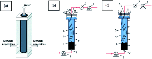
2.2.1 Preparation of HF-PVDF-CNT membranes. The membrane module was applied with an effective area of 17.58 cm2. The HF-PVDF carriers were pretreated by soaking in a 50% ethanol solution for 12 hours. Following this, tap water was employed to rinse the carriers and remove all the alcohol, before the material was dried. The HF-PVDF-CNT membranes were prepared in a constant-flow and dead-end filtration mode. The device is shown in Fig. 1(a). The PD/CNTs dispersion was prepared according to a similar method to that of Zhu et al.24 That is, the CNTs dispersion was first prepared by adding 750 mg of CNTs and 10 ml of Triton X-100 to 1000 ml of Milli-Q water (18 MΩ cm−2). The CNTs mixture was dispersed by sonicating for 30 min (240 W) and then magnetically stirred at 50 °C for 12 h. Subsequently, 100 mg of dopamine was dissolved once in the CNTs dispersion mentioned above, with sonication for 30 min (240 W). 100 ml of fresh HCl–Tris (0.1 mol L−1, pH = 8.5) was poured into the above solution and further stirred for 24 h at 50 °C. Then the solution was dispersed by 30 min of sonication (240 W). A PD/CNTs dispersion was obtained. CNT mats were created or HF-PVDF-CNT membranes were prepared by filtering the dispersion through the membrane module in an out–in mode using a peristaltic pump (Fig. 1(a)). The CNTs loading was maintained at ≈2.13 g CNT m−2 in our experiments.
image file: c9ra07542a-f1.tif
Fig. 1 (a) The device utilized for the preparation of HF-PVDF-CNT membranes. (b) A schematic representation of reactor R2: (1) peristaltic pump; (2) feed; (3) sludge zone; (4) reaction column; (5) HF-PVDF membrane module; (6) permeate; (7) pressure transducer; (8) peristaltic pump for outflow; (9) pH electrode; (10) ORP electrode; (11) DO electrode; (12) gas bag; (13) reference electrode; (14) cathode probe; (15) anode probe. (c) A schematic representation of reactor R1: (1) peristaltic pump; (2) feed; (3) sludge zone; (4) reaction column; (5) HF-PVDF membrane module; (6) permeate; (7) pressure transducer; (8) peristaltic pump for outflow; (9) pH electrode; (10) ORP electrode; (11) DO electrode; (12) gas bag.
2.2.2 Stability evaluation of CNT mats towards backwashing. The stability of the CNT mats on the outer surface of the membranes was evaluated by hydraulic backwashing for 2 h at a flow rate of 300 L m−2 h−1 through HF-PVDF-CNT membranes from inside to outside. 45 ml of backwashing water was collected into a 50 ml colorimetric tube every ten minutes (Fig. S2). The mass of CNTs dislodged from the mats can be determined by UV-vis analysis in accordance with previous research by Gallagher et al.19 In detail, 3 mg of CNTs powder was mixed with 1% (v/vH2O) Triton X-100 in 1000 ml of Milli-Q water (pH = 10), and sonicated for 15 min under a power of 240 W. A CNTs dispersion was obtained. And then the UV average absorbance of the CNTs dispersion was measured in the 200–900 nm range. At the same time, 1% (v/vH2O) Triton X-100 solution was prepared in the same way and its UV average absorbance was determined in the 200–900 nm range. The results showed that the Triton X-100 molecules do not show any absorbance but CNTs show obvious absorbance in the 800–900 nm range (Fig. S1). A standard curve was derived from the serial CNTs dispersions with 0.5% (v/vH2O) Triton X-100 at 850 nm in the customary way (Fig. S3). Based on this information, the mass of CNTs released from the CNT mats in the backwashing water was determined by UV analysis. In addition, the conductive stability was tested by measuring the conductivity before and after water backwashing. The water during backwashing was prepared by mixing tap water with NaOH solution. The pH of the backwashing water was 10.
2.2.3 Membrane antifouling properties during filtration of BSA, SA and HA. The resistance to fouling of the HF-PVDF and HF-PVDF-CNT membranes was evaluated by recording TMP every two minutes during three cycles of filtration in different solutions, such as BSA, SA or HA, prepared according to the methods given in Section 2.1.1. The filtration was done in a continuous flow mode (Fig. S4). But there were some slight differences in each filtration experiment. The filtration of BSA solution was conducted with a final TMP of 30 kPa each cycle, while the filtration cycle lasted for 80 and 60 min during filtration of HA and SA solutions, respectively. Except for TMP, the effluent of the filtration was collected over a given period to explore the rejection capacity. The backwash steps were carried out for 10 min at 300 L m−2 h−1 after every cycle of filtration. Before filtration, the modified and unmodified membranes were soaked in Milli-Q water for 30 min and the filtration water was collected directly into a measuring cylinder for ten minutes at 30 kPa, in order to calculate the water flux (J1). To further study the membrane fouling resistance, the water flux (J2) through the membrane was measured at 30 kPa after the first backwash step for every pollutant filtration experiment.
2.2.4 AnMBR and AnEMBR systems. Schematic diagrams of the tubular R1 and R2 systems are shown in Fig. 1(b) and (c). The actual set-ups are shown in Fig. S5. AnEMBR reactor R2 was constructed in a similar way to the system described by Katuri et al.28 The AnEMBR reactor (50 cm length, 9.4 cm internal diameter) had a working volume of 3.2 L. The sludge zone as the anode was made up of cylindrical carbon-graphite felt containing a platinum core, which was positioned vertically at the bottom of the reactor. For the carbon-graphite felt, its bottom radius was 8 cm and its height was 10 cm. The anaerobic sludge all adhered strongly to the felt. The HF-PVDF-CNT membrane module as the cathode was positioned vertically at the top of the reactor with the end of the fibers positioned approximately 5 cm from the top of the anode. The anode and cathode were connected separately with the electrochemical workstation through copper wires. A head space gas sampling bag and the electrodes of ORP, pH online detectors and reference were provided on the top of the reaction columns. The systems were inoculated with anaerobic sludge from a secondary sedimentation tank of Beijing Gaobeidian sewage treatment plant. The systems were fed with synthetic municipal wastewater (Table S1), and operated in a continuous flow mode at room temperature. The average room temperature was 28 °C during the experiments. The HRT of the reactor was 36 h, and the sludge concentration (MLSS) in every reactor was 3000 mg L−1. The start and operation of the system were under the condition of an applied voltage of −0.5 V (vs. Ag/AgCl) on the membrane surface from the electrochemical workstation. In contrast to R2, the AnMBR system R1 was constructed and operated as described above, except that the sludge zone was only pure anaerobic sludge without any additional voltage being used. R1 was constructed in this way in order to compare the fouling resistance of the HF-PVDF-CNT membrane in terms of TMP.

2.3 Measuring methods

2.3.1 Characteristics of HF-PVDF and HF-PVDF-CNT membranes. The cross-section and surface morphologies were observed by scanning electron microscopy (SEM, SU8020, Japan). The chemical structures of the CNT mats were detected by a Fourier infrared spectrometer (FTIR, Nicolet iS10, USA). The surface hydrophilicity was characterized on the basis of static contact angle measured by the site-drop method using a DataPhysics Contact Angle Tester (OCA50, Germany). The porosity of the membranes was determined by the mass loss of the wet membranes after drying.29 The bubble point method was used to estimate the permeation flux at 0.1 MPa. The adhesion stability of the CNT mats through hydraulic backwashing was evaluated by UV-visible analysis (Shimadzu, Japan). The conductivity of the CNT mats was investigated via the four-probe method30 before and after backwashing to better characterize the stability. The electrical conductivity of the modified membrane σf was calculated from the conductivity σ1, assuming a hypothetical sample thickness of 1 cm, with the actual thickness df (in cm) as σf = σ1/df.
2.3.2 Analysis of water quality. For the filtration of BSA, HA and SA as in Section 2.2.3, the rejection rate of the pollutant was calculated from the equation:31
image file: c9ra07542a-t1.tif
where Cp and Cf are the pollutant concentrations in the permeate and feed, respectively.

The membrane water flux was calculated from the following equation:31

image file: c9ra07542a-t2.tif
where M (kg) is the weight of filtered water, A (m2) is the membrane area and ΔT (h) is the filtration time.

The flux recovery ratio was calculated by means of the following expression:32

image file: c9ra07542a-t3.tif

Soluble chemical oxygen demand (SCOD) and chemical oxygen demand (COD) concentrations were determined by standard methods.33 COD removal efficiency, the contribution of biological removal rate to the COD value and the contribution of membrane separation rate to the COD value were calculated as follows:

image file: c9ra07542a-t4.tif
contribution of biological removal rate to the
image file: c9ra07542a-t5.tif
contribution of membrane separation rate to the
image file: c9ra07542a-t6.tif
where CODin, CODef, CODsup are the COD concentrations of influent, effluent and supernatant.

The transmembrane pressure (TMP) of the membrane modules was monitored with a pressure transducer (JYB-3151, Beijing, China) to explore the antifouling performance. UV absorbance measurements at 254 nm (UV254) and total organic carbon (TOC) were applied to serve as simple and reliable surrogate parameters to monitor the removal of HA. So UV-vis analysis was employed to analyze the concentration of HA. The protein content was estimated by the Coomassie bright blue method.34 The polysaccharide content in SA solutions was determined via the sulfuric acid–phenol method.35

3. Results and discussion

3.1 Characteristics of HF-PVDF and HF-PVDF-CNT membranes

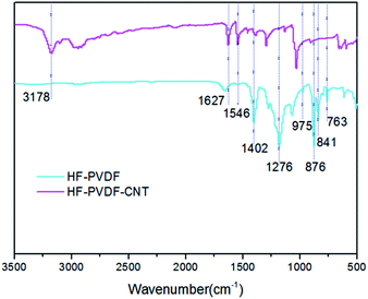
3.1.1 Infrared spectrum analysis. The FITR spectra showed significant differences before and after membrane modification (Fig. 2). The HF-PVDF materials had strong correlation peaks for different PVDF crystal types, such as 975, 876 and 763 cm−1 (alpha-PVDF crystal) or at 1402, 1276 and 841 cm−1 (beta-PVDF crystal). After surface modification, the PVDF correlation peaks were significantly weakened and new responses appeared at 1546, 1627 and 3178 cm−1. The strong absorbance of the HF-PVDF-CNT membranes at 1546 cm−1 was attributed to the framework vibration peak of the benzene ring or the bending vibration peak of N–H, which may be closely related to the benzene ring structure and –NH2 of dopamine molecules.36 A new peak at 1627 cm−1 was due to the stretching vibration peak of carbonyl and another peak at 3178 cm−1 was due to the amino groups or carboxyl groups. Two peaks (1627 and 3178 cm−1) suggest that CNT mats were formed on the membrane outer surface. Furthermore, these findings prove that CNTs and dopamine were successfully coated on the surfaces of the HF-PVDF membrane, and dopamine may even have certain modification effects on CNTs.37
image file: c9ra07542a-f2.tif
Fig. 2 Infrared spectra of the HF-PVDF and HF-PVDF-CNT membrane surfaces.
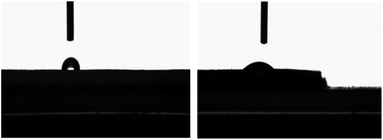
3.1.2 Static contact angle analysis. Fig. 3 shows that the water contact angles (WCAs) for HF-PVDF and HF-PVDF-CNT membranes were 87.5 ± 5° and 34.6 ± 2°, respectively. The initial WCA declined by roughly 52.9° when the CNT mats were introduced. This suggests that the hydrophobicity was changed into hydrophilicity for the membrane surface. This phenomenon can be rationalized by hydrophilic groups, such as –OH, –COOH and –NH2, and the nano material surfaces greatly improving the hydrophilicity of the membrane surface.
image file: c9ra07542a-f3.tif
Fig. 3 Static contact angles of the HF-PVDF (left) and HF-PVDF-CNT (right) membrane surfaces.
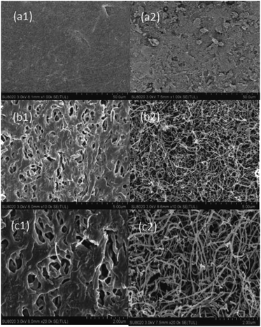
3.1.3 Morphological characterization of the membrane surfaces. The outer surface microscopic structure of the HF-PVDF and HF-PVDF-CNT membranes was observed with a scanning electron microscope (SEM) and the result is shown in Fig. 4. It can be seen that micron-size pores were relatively dense and uniform in the HF-PVDF membranes which were easily covered by CNTs. And it could also be seen that a network porous structure was formed from interconnected CNT bundles with a high porosity on the modified membrane surfaces. The network structure was made of CNT mats. The CNT mats on the modified membrane surfaces may be beneficial to the inhibition of adsorption of pollutants. This may be owing to the increased disturbance caused by water flow.25
image file: c9ra07542a-f4.tif
Fig. 4 Surface morphologies of the HF-PVDF (a1, b1 and c1) and HF-PVDF-CNT (a2, b2 and c2) membranes.
3.1.4 Porosity and water flux analysis. The porosity and pure water permeation flux before and after modification are shown in Table 1. It was found that the total porosity of the HF-PVDF-CNT membrane actually increased by about 13%. This may be due to the bundle of CNT mats with high porosity on the HF-PVDF-CNT membrane surfaces. Unfortunately, the water permeability flux declined from 5670 ± 15 L m−2 h−1 to 637 ± 20 L m−2 h−1 after the introduction of CNT mats. The permeability rate reduced by approximately 89% after modification. There are two main reasons for this disadvantage. On the one hand, the adhesion of dopamine-bound CNTs to the membrane surface or into the membrane pores during filtration in modified membrane module preparation, resulted in membrane pore blockage. On the other hand, the PD/CNTs dispersion may be not mixed thoroughly and the CNTs might not be absolutely uniformly distributed on the membrane surface. But it cannot be ignored that the modified membrane surface was hydrophilic. Thus, the good wettability of CNT mats had little effect on the increase in water flux, which is in accordance with the results reported in other literature.38 And Gethard et al. found that the partial penetration of CNTs into HF-PVDF membrane pores partially reduces the hydraulic resistance of water molecules in the support layer.39 For our experiment, the decreased water flux suggests that the hydraulic resistance of water molecules in the membrane may be greatly increased and the effect of CNTs in the membrane pores was very small.
Table 1 Pure water flux and porosity properties of the membranes before and after modification
Sample J (L m−2 h−1) ε (%)
HF-PVDF 5670 ± 15 34.87 ± 5
HF-PVDF-CNT 637 ± 20 47.51 ± 4


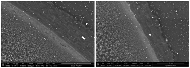
3.1.5 Conductivity test. The conductivity of the HF-PVDF-CNT membrane before and after water backwashing was tested. It can be seen that the thickness of the CNT mats was 30 ± 5 μm according to the SEM image (Fig. 5). The average resistivity was 176.51 Ω cm−1 for the HF-PVDF-CNT membranes, but it increased to 316.63 Ω cm−1 after backwashing. Thus, the conductivities of modified membrane before and after backwashing were calculated to be 0.071–0.214 s mm−1 and 0.040–0.119 s mm−1, respectively. HF-PVDF-CNT membranes exhibiting relatively stable electrical conductivity lay the foundation for AnEMBR applications.
image file: c9ra07542a-f5.tif
Fig. 5 Cross-sectional morphologies of the HF-PVDF-CNT membrane.

3.2 Stability analysis of CNT mats towards backwashing

The stability of CNT mats of the HF-PVDF-CNT membrane before and after backwashing was tested by UV-visible analysis. During the whole backwashing process, there was only 0.20 mg of CNTs detected in the backwashing water, accounting for 0.54% of the total load of CNTs (see Table S4). This may be because the greatest stress experienced by the CNT mats loaded on the outer surface of membranes was the tensile hoop stress, when trying to expand the materials during backwashing.40 It may be speculated that the dopamine induced firm adhesion between the membrane surface and CNTs or among CNTs. The adhesion stress was more effective than the tensile cyclic stress, in preventing CNTs from shedding. However, the mechanical properties of the HF-PVDF-CNT membrane were poor. Slight stretching or rotation of the membrane resulted in severe shedding of CNTs from the CNT mats on the membrane surface.

3.3 Anti-fouling ability of the HF-PVDF-CNT membrane

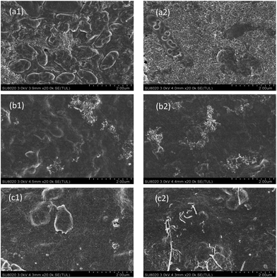
3.3.1 Effects of BSA solution on membrane fouling. The anti-fouling properties of BSA solution on the HF-PVDF and HF-PVDF-CNT membrane are shown in Fig. 6(a). The average TMP growth rates of the HF-PVDF membrane in the three filtration cycles were 0.21, 1.67 and 3.00 kPa min−1, respectively. In comparison, the average TMP growth rates of the HF-PVDF-CNT membrane every cycle were significantly lower, at 0.17, 1.07 and 1.67 kPa min−1, respectively. The service life of the HF-PVDF-CNT membranes within three filtration cycles was extended by 29%. And this was verified by SEM images (Fig. 7(a1) and (a2)). The surface of the HF-PVDF membrane was covered by a large area of massive pollutants but the HF-PVDF-CNT membrane showed lower coverage after filtration. There were more pores in the HF-PVDF-CNT membrane than in the HF-PVDF membrane. Some studies have found that the interaction between proteins and membranes is the result of electric charges.41 Under neutral conditions, negatively charged BSA has an electrostatically repulsive effect on the carboxyl groups of CNT mats. Membrane fouling was effectively alleviated by preventing chemical adsorption between the carboxyl groups of the CNT mats and the protein amino groups.
image file: c9ra07542a-f6.tif
Fig. 6 Relationships between TMP and time when BSA (a), SA (b) or HA (c) solution was filtered by the HF-PVDF and HF-PVDF-CNT membranes.

image file: c9ra07542a-f7.tif
Fig. 7 SEM images of the HF-PVDF membrane polluted by BSA (a1), SA (b1) or HA (c1) solution; SEM images of the HF-PVDF-CNT membrane polluted by BSA (a2), SA (b2) or HA (c2) solution.

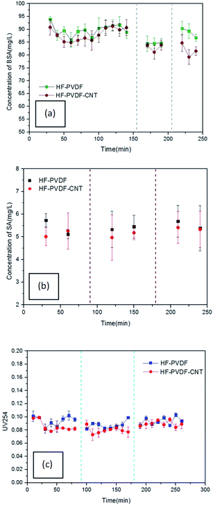
Meanwhile, the BSA concentration of the filtered water through the HF-PVDF-CNT membrane was significantly lower than the that through the HF-PVDF membrane, as shown in Fig. 8(a). This may be ascribed to the charges on the modified membrane surface and the CNT mats. pH 4.7 is the isoelectric point of BSA. The negatively charged BSA molecules affect membrane fouling because of the electrostatic interactions among organic foulants and between organic foulants and the membrane surface directly.42 In addition, the complex porosity structure on the surface of HF-PVDF-CNT membranes helped to trap the BSA molecules and increased the rejection.


image file: c9ra07542a-f8.tif
Fig. 8 Relationships between the concentration of effluent contaminant and time when BSA (a), SA (b) or HA (c) solution was filtered by the membranes.
3.3.2 Effects of SA solution on membrane fouling. The anti-fouling performance of SA solution on the HF-PVDF and HF-PVDF-CNT membranes is shown in Fig. 6(b). It should be noticed that the TMP increase of the HF-PVDF membrane increased rapidly. The TMP variation of the HF-PVDF-CNT membrane showed a slower, more linear rate of increase. This could be a reflection of the formation steps of pore blockage and cake filtration.43 Unfortunately, both HF-PVDF and HF-PVDF-CNT membrane surfaces were heavily covered by a layer of SA pollutants in the end (Fig. 7(b1) and (b2)). As reported in the study by Moshe et al.,44 SA has a great effect on adsorption onto the two membrane types (adsorption efficiencies of 61.2–88.7% for SA).44

In addition, the rejection rate of SA with the HF-PVDF-CNT membrane was improved (Fig. 8(b)), as we expected. The HF-PVDF-CNT membrane had a greater effect on the osmosis separation compared with the HF-PVDF membrane. This could be ascribed to the zwitterionic molecular structure45 and highly hydrophilic CNT mats on the membrane surfaces.

3.3.3 Effects of HA solution on membrane fouling. The effect of HA solution on membrane contamination is shown in Fig. 6(c). The results showed that the average TMP growth rates during each filtration cycle through the HF-PVDF membrane were 0.50, 0.81 and 0.87 kPa min−1, respectively. In comparison, the TMP growth rates during each filtration cycle through the HF-PVDF membrane were significantly higher than those for the HF-PVDF-CNT membrane, which were 0.20, 0.38 and 0.545 kPa min−1, respectively. As can be seen from the SEM images (Fig. 7(c1) and (c2)), visible CNTs on the surface of the contaminated HF-PVDF-CNT membrane were further evidence that the CNT mats were able to reduce the adhesion of HA molecules. Generally, humic acid has an amphoteric structure with –COOH and –OH hydrophilic functional groups and hydrophobic aromatic and fatty groups in the molecular center.46 Therefore, the hydrophilic HF-PVDF-CNT membrane was more resistant to membrane fouling than the HF-PVDF membrane.

Furthermore, it was found that the UV254 values of most effluent samples for the HF-PVDF-CNT membrane were lower than those for the HF-PVDF membrane (Fig. 8(c)). The average effluent UV254 values during filtration of every cycle through the HF-PVDF membrane were 0.094, 0.088 and 0.094, respectively, while the average effluent UV254 values during filtration of each cycle through the HF-PVDF-CNT membrane were 0.085, 0.080 and 0.089, respectively. For the two membrane types, the UV254 values of the effluent generated from the second cycle were the lowest, while the UV254 values of the effluent during the first and third cycles were poor. The variation trend of the UV254 values in effluent for all three cycles was consistent with the findings reported by Lowe et al.47 When the HA solution was filtered in the first cycle, HA molecules were at a high concentration and could easily pass through the membrane pores. With extended filtration time, the formation of cake layers on the membrane surfaces led to shrinkage and reduction of the pores. And the organic substance in the membrane filtered water decreased accordingly. Backwashing after filtration did not prevent or slow down the formation of cake layers or irreversible pollutants. When the layers of pollutants on the membrane surfaces became thick enough, a large concentration difference was formed around the membrane. Furthermore, concentration polarization was caused on the membrane surfaces. The organic concentration in the effluent increased gradually with the accelerated migration of HA molecules.

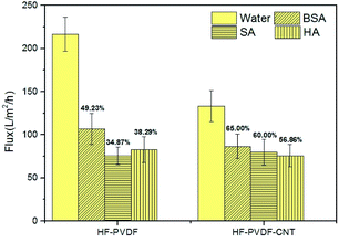
3.3.4 Recovery of membrane backwash water flux. As shown in Fig. 9, the water permeation flux of the HF-PVDF membrane decreased more than that of the HF-PVDF-CNT membrane after backwashing. The gap in pure water permeation flux between the two membranes after filtration of BSA, SA or HA solution, was significantly reduced. Reversible fouling was prone to be induced on the HF-PVDF-CNT membrane and the water flux was easily recovered by backwashing. These are consistent with the reported findings of Jung et al.48 Although the pure water flux of the modified membranes decreased seriously, there is a certain application value for coating dopamine and CNTs on the HF-PVDF membrane.
image file: c9ra07542a-f9.tif
Fig. 9 Membrane water flux recovery ratios after backwashing.

3.4 Application of HF-PVDF and HF-PVDF-CNT membranes in MBRs

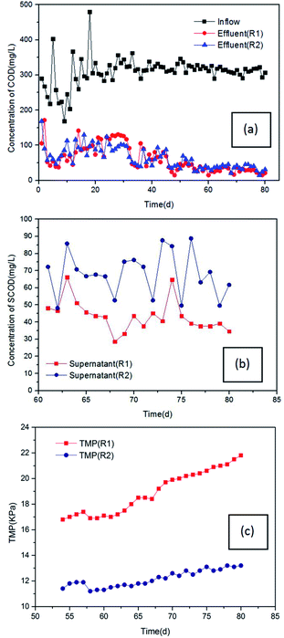
3.4.1 Operational performance of AnMBR and AnEMBR. Fig. 10(a) and (b) show COD removal efficiency in the anaerobic membrane bioreactors R1 (AnMBR) and R2 (AnEMBR). The COD concentrations in effluent of both bioreactors decreased greatly within 50 days and gradually stabilized after 50 d. During the stable operation, the average COD in effluent of the reactors R1 and R2 were 30.67 and 39.62 mg L−1, respectively (Fig. 9(a)), while the SCOD concentrations in the supernatant of the R1 and R2 systems were at 43.49 and 68.07 mg L−1, respectively (Fig. 9(b)). It could be seen that the removal of COD was very close in both reactors during the whole operational period; the biological treatment contribution rates of R1 and R2 were 95.49% and 89.67%, respectively. The membrane separation contribution rates of R1 and R2 were 4.51% and 10.33%, respectively. Obviously, the contribution rate of membrane separation in R2 was much higher than in R1. This could be because the biofilm on the cathode surface has a positive effect on organic degradation, with the application of a voltage accelerating electron transfer among microorganisms or between the cathode and microorganisms.49
image file: c9ra07542a-f10.tif
Fig. 10 (a) COD concentration in the inflow and effluent over the time of operation of R1 and R2. (b) SCOD concentration in the supernatant during the stable period in R1 and R2. (c) TMP evolution during the operation of R1 and R2.
3.4.2 Membrane fouling characteristics of AnEMBR. The TMP of the membrane modules was measured during stable operation (Fig. 10(c)). The TMP in R1 stabilized at 17.0 kPa and then increased gradually. However, R2 showed a slower upward trend and remained stable at about 12 kPa during the whole process, which was much lower than for R1. Similar to the findings of Yang et al.,50 the above phenomenon could be attributed to the electrostatic repulsion between the pollutants and cathode surfaces being enhanced with an applied voltage. But further research and analysis are needed to explore the relationship between applied voltage and membrane fouling.

4. Conclusions

In summary, a novel and simple technique to fabricate CNT conductive composite membranes was introduced in our study. The method involves filtering a PD/CNTs dispersion through a HF-PVDF membrane operating in dead-end mode from the outside-in. The characteristics of the modified membrane were described. The antifouling performance with different contaminants was investigated compared with the unmodified membrane. The obtained results show that:

(1) The CNT mats on the modified membrane surfaces were very stable during hydraulic backwashing. In addition, the CNT mats endowed the unmodified membrane with high hydrophilicity and conductivity.

(2) The antifouling and rejection performance of the modified membrane was significantly improved compared with the unmodified membrane during the filtration of BSA, SA or HA solution. Furthermore, the modified membrane is superior in terms of membrane water permeation flux recovery compared with the unmodified membrane. This is further evidence of the high antifouling performance of the modified membrane.

(3) The electro-assisted CNT mats on the outer surface of the modified membrane exhibited high antifouling and separation performance. The results confirmed that biofouling could be mitigated with the application of a voltage in the AnEMBR system.

Conflicts of interest

There are no conflicts to declare.

Acknowledgements

The authors acknowledge funding support from the National Natural Science Foundation of China (51478015).

References

  1. G. Skouteris, D. Hermosilla, P. López, C. Negro and Á. Blanco, Chem. Eng. J., 2012, 198, 138–148 CrossRef.
  2. A. Ramesh, D. J. Lee, M. L. Wang, J. P. Hsu, R. S. Juang, K. J. Hwang, J. C. Liu and S. J. Tseng, Sep. Sci. Technol., 2006, 41, 1345–1370 CrossRef CAS.
  3. A. Ramesh, D. Lee and J. Lai, Appl. Microbiol. Biotechnol., 2007, 74, 699–707 CrossRef CAS.
  4. M. Tao, F. Liu and L. Xue, J. Mater. Chem., 2012, 22, 9131–9137 RSC.
  5. X. Yang, Y. He, G. Zeng, X. Chen, H. Shi, D. Qing, F. Li and Q. Chen, Chem. Eng. J., 2017, 321, 245–256 CrossRef CAS.
  6. N. Yamato, K. Kimura, T. Miyoshi and Y. Watanabe, J. Membr. Sci., 2006, 280, 911–919 CrossRef CAS.
  7. J.-G. Choi, T.-H. Bae, J.-H. Kim, T.-M. Tak and A. Randall, J. Membr. Sci., 2002, 203, 103–113 CrossRef CAS.
  8. V. Gekas, K. M. Persson, M. Wahlgren and B. Sivik, J. Membr. Sci., 1992, 72, 293–302 CrossRef CAS.
  9. X. Xie, C. Criddle and Y. Cui, Energy Environ. Sci., 2015, 8, 3418–3441 RSC.
  10. B. J. Hinds, N. Chopra, T. Rantell, R. Andrews, V. Gavalas and L. G. Bachas, Science, 2004, 303, 62–65 CrossRef CAS PubMed.
  11. A. López-Lorente, B. Simonet and M. Valcárcel, Anal. Chem., 2010, 82, 5399–5407 CrossRef PubMed.
  12. L. Liu, J. Liu, B. Gao, F. Yang and S. Chellam, J. Membr. Sci., 2012, 394, 202–208 CrossRef.
  13. A. Ding, Y. Yang, G. Sun and D. Wu, Chem. Eng. J., 2016, 283, 260–265 CrossRef CAS.
  14. Y. Yang, S. Qiao, R. Jin, J. Zhou and X. Quan, J. Membr. Sci., 2018, 553, 54–62 CrossRef CAS.
  15. S. Madaeni, S. Zinadini and V. Vatanpour, Sep. Purif. Technol., 2011, 80, 155–162 CrossRef CAS.
  16. G. S. Ajmani, D. Goodwin, K. Marsh, D. H. Fairbrother, K. J. Schwab, J. G. Jacangelo and H. Huang, Water Res., 2012, 46, 5645–5654 CrossRef CAS PubMed.
  17. J. C. Hoepfner, M. R. Loos and S. H. Pezzin, J. Appl. Polym. Sci., 2019, 136, 48146 CrossRef.
  18. Y. Liu, Y. Su, J. Cao, J. Guan, L. Xu, R. Zhang, M. He, Q. Zhang, L. Fan and Z. Jiang, Nanoscale, 2017, 9, 7508–7518 RSC.
  19. M. Gallagher, H. Huang, K. Schwab, D. Fairbrother and B. Teychene, J. Membr. Sci., 2013, 446, 59–67 CrossRef CAS.
  20. Z.-Y. Xi, Y.-Y. Xu, L.-P. Zhu, Y. Wang and B.-K. Zhu, J. Membr. Sci., 2009, 327, 244–253 CrossRef CAS.
  21. J. Jiang, L. Zhu, L. Zhu, B. Zhu and Y. Xu, Langmuir, 2011, 27, 14180–14187 CrossRef CAS PubMed.
  22. B. Fei, B. Qian, Z. Yang, R. Wang, W. Liu, C. Mak and J. H. Xin, Carbon, 2008, 46, 1795–1797 CrossRef CAS.
  23. P. Yan, J. Wang, L. Wang, B. Liu, Z. Lei and S. Yang, Appl. Surf. Sci., 2011, 257, 4849–4855 CrossRef CAS.
  24. Y. Zhu, W. Xie, S. Gao, F. Zhang, W. Zhang, Z. Liu and J. Jin, Small, 2016, 12, 5034–5041 CrossRef CAS.
  25. S. Kang, A. Asatekin, A. M. Mayes and M. Elimelech, J. Membr. Sci., 2007, 296, 42–50 CrossRef CAS.
  26. F. Li, Q. Tian, B. Yang, L. Wu and C. Deng, Desalination, 2012, 286, 34–40 CrossRef CAS.
  27. J. Na and Z. Yonggang, 2010 3rd International Conference on Environment and Computer Science, Kunming, 2011 Search PubMed.
  28. K. P. Katuri, C. M. Werner, R. J. Jimenez-Sandoval, W. Chen, S. Jeon, B. E. Logan, Z. Lai, G. L. Amy and P. E. Saikaly, Environ. Sci. Technol., 2014, 48, 12833–12841 CrossRef CAS.
  29. J. Xu and Z.-L. Xu, J. Membr. Sci., 2002, 208, 203–212 CrossRef CAS.
  30. L. J. van der Pauw, Philips Res. Rep., 1958, 20, 220–224 Search PubMed.
  31. V. Vatanpour, S. S. Madaeni, R. Moradian, S. Zinadini and B. Astinchap, J. Membr. Sci., 2011, 375, 284–294 CrossRef CAS.
  32. V. Vatanpour, S. S. Madaeni, L. Rajabi, S. Zinadini and A. A. Derakhshan, J. Membr. Sci., 2012, 401, 132–143 CrossRef.
  33. American Public Health Association, American Water Works Association and Water Environmental Federation, Standard methods for the examination of water and wastewater, American Public Health Association (APHA), Washington, DC, 2005 Search PubMed.
  34. J. J. Sedmak and S. E. Grossberg, Anal. Biochem., 1977, 79, 544–552 CrossRef CAS PubMed.
  35. M. Dubois, K. A. Gilles, J. K. Hamilton, P. t. Rebers and F. Smith, Anal. Chem., 1956, 28, 350–356 CrossRef CAS.
  36. J. T. Arena, B. McCloskey, B. D. Freeman and J. R. McCutcheon, J. Membr. Sci., 2011, 375, 55–62 CrossRef CAS.
  37. Q. Wan, J. Tian, M. Liu, G. Zeng, Q. Huang, K. Wang, Q. Zhang, F. Deng, X. Zhang and Y. Wei, Appl. Surf. Sci., 2015, 346, 335–341 CrossRef CAS.
  38. J. T. Arena, S. S. Manickam, K. K. Reimund, B. D. Freeman and J. R. McCutcheon, Desalination, 2014, 343, 8–16 CrossRef CAS.
  39. K. Gethard, O. Sae-Khow and S. Mitra, ACS Appl. Mater. Interfaces, 2010, 3, 110–114 CrossRef PubMed.
  40. A. Gijsbertsen-Abrahamse, E. Cornelissen and J. Hofman, Desalination, 2006, 194, 251–258 CrossRef CAS.
  41. P. Heinemann, J. Howell and R. Bryan, Desalination, 1988, 68, 243–250 CrossRef CAS.
  42. H. Matsumoto, Y. Koyama and A. Tanioka, J. Colloid Interface Sci., 2003, 264, 82–88 CrossRef CAS.
  43. D. M. Kanani, X. Sun and R. Ghosh, J. Membr. Sci., 2008, 315, 1–10 CrossRef CAS.
  44. M. Herzberg, S. Kang and M. Elimelech, Environ. Sci. Technol., 2009, 43, 4393–4398 CrossRef CAS.
  45. M. Hadidi and A. L. Zydney, J. Membr. Sci., 2014, 452, 97–103 CrossRef CAS.
  46. K. Ghosh and M. Schnitzer, Soil Sci., 1980, 129, 266–276 CrossRef CAS.
  47. J. Lowe and M. M. Hossain, Desalination, 2008, 218, 343–354 CrossRef CAS.
  48. C.-W. Jung, H.-J. Son and L.-S. Kang, Desalination, 2006, 197, 154–164 CrossRef CAS.
  49. Y.-K. Wang, W.-W. Li, G.-P. Sheng, B.-J. Shi and H.-Q. Yu, Water Res., 2013, 47, 5794–5800 CrossRef CAS PubMed.
  50. Y. Yang, S. Qiao, R. Jin, J. Zhou and X. Quan, Environ. Sci. Technol., 2018, 53, 1014–1021 CrossRef PubMed.

Footnote

Electronic supplementary information (ESI) available. See DOI: 10.1039/c9ra07542a

This journal is © The Royal Society of Chemistry 2020