 Open Access Article
Hydrophilic SiC hollow fiber membranes for low fouling separation of oil-in-water emulsions with high flux
Man Xuab,
Chenxi Xua,
K. P. Rakesh a,
Yuge Cuia,
Jun Yina,
Changlian Chenab,
Shulin Wangab,
Bingcai Chena and
Li Zhu
 *ab
*ab
aSchool of Materials Science and Engineering, Wuhan Institute of Technology, Wuhan, Hubei, China, 430073. E-mail: lzhu@wit.edu.cn; Fax: +86-27-87905136; Tel: +86-27-87905136
bEngineering Research Center of Environmental Materials and Membrane Technology of Hubei Province, Wuhan, Hubei, China 430073
First published on 29th January 2020
Abstract
The dry-wetting spinning technique involving immersion-induced phase inversion and dry-sintering was applied to prepare two types of SiC and Al2O3 hollow fiber membranes. The two hollow fiber membranes were characterized in terms of morphology and chemical surface composition by scanning electron microscopy (SEM), X-ray photoelectron spectroscopy (XPS), water contact angle and zeta potential measurements. The filtration capabilities of the two hollow fiber membranes were assessed by the separation of 200 mg L−1 synthetic (O/W) emulsions. During the treatment of O/W emulsions, the permeation flux of the SiC hollow fiber membrane was 163.9 L h−1 m−2, which was higher than that of the Al2O3 hollow fiber membrane (139.4 L h−1 m−2) at the beginning of the experiment. The membrane surface properties and the filtration results of O/W emulsion microfiltration demonstrated that the SiC hollow fiber membranes with a higher hydrophilicity had higher water flux and better anti-fouling properties.
1. Introduction
Large amounts of oily wastewater pollution are being produced by industrial and residential applications, leading to a global risk for the environment and human health.1–3 Lots of oil-in-water pollutants exist in emulsion form (O/W emulsions) and O/W emulsions are the most difficult to remove effectively, so O/W emulsion separation has double significance in ecology and economics.4Membrane separation technology has become an emerging technology for the treatment of O/W emulsions due to merits such as high flux, low reprocessing cost, less energy consumption, and less environmental pollution.5 Nowadays, inorganic and polymeric membranes have been successfully employed for the separation of O/W emulsions.6 However, the main drawback of polymeric membranes in O/W emulsion treatment is their inherent hydrophobicity resulting in a high fouling tendency, which often leads to flux decrease in membrane performances.7 Membrane fouling (including reversible and irreversible fouling) leads to the severe decline of permeate flux and thus compromises the membrane performance. Accordingly, mechanical and chemical cleaning is ultimately required.1 In the direction of mitigate membrane fouling problems, one of the solutions is to develop a hydrophilic membrane which provides an enhanced hydrophilic character of membrane surface that can resist oil attachment and thus effectively prohibit permeation flux decline.8
Ceramic membranes made from ceramic powders including Al2O3, TiO2, ZrO2, are considered to be superior to polymeric membranes for the treatment of oily wastewater as they have improved hydrophilicity.9–12 As such, there is a growing interesting in using inorganic membranes for purifying O/W emulsions in recent years.13,14 However, like polymeric membranes, ceramic membranes also suffer from fouling during the treatment of O/W emulsions more or less.15 The performance of ceramic membranes for O/W emulsions treatment must be continually improved. In this process, more hydrophilic membrane material and preparation technologies toward making ceramic membranes with good antifouling properties should be developed.16
Compared with polymeric and ceramic membranes (oxide materials membrane, such as Al2O3, TiO2, and ZrO2), SiC membranes are very hydrophilic.17–19 Therefore, SiC membranes20 have a high potential for oil separation and oily wastewater treatment applications because of their hydrophilicity, superb fouling resistance, and chemical stability.21 SiC membranes have various configurations such as flat, tubular,22 and hollow fibers.23 For large scale applications, the hollow fiber configuration has higher packing density and higher water flux compared to the flat membrane.24,25 However, few reports regard the O/W emulsions separation using the SiC hollow fiber membrane, not to mention the effect of surface property on the SiC hollow fiber membrane filtration performance in the treatment of O/W emulsions separation process.
In the present study, two types of SiC and Al2O3 hollow fiber membranes were prepared through the dry-wetting spinning technique involving immersion-induced phase inversion and dry-sintering method to mitigate the fouling of ceramic membranes in O/W emulsions treatment. The performance and fouling of the membranes by separation of O/W emulsions are compared under the same cross-filtration conduction and backwash procedure thus to obtain a better understanding of the relationship between the membrane fouling and surface property of the SiC hollow fiber membranes and Al2O3 hollow fiber membranes, thus to provide new insight into the membrane fouling control.
2. Material and methods
2.1 Fabrication and characterization of SiC and Al2O3 hollow fiber membranes
Commercially available SiC powders (purchased from Zhengzhou Lifeng, Abrasive Tools Co., Ltd) and Al2O3 powders (purchased from Nanjing Tansail Advanced Materials Co., Ltd) with an average particle diameter of 3.54 μm and 3.09 μm were used for the preparation of SiC and Al2O3 hollow fiber membranes. Polyethersulfone (PESf, Technical Pure, Radel A-100, Solvay Advanced Polymers, L. L. C.), N-methyl-2-pyrrolidone (NMP, Chemical Pure, Sinopharm Chemical Reagent Co., Ltd, China) and polyvinylpyrrolidone (PVP, Chemical Pure, Sinopharm Chemical Reagent Co., Ltd, China) were used as the binder, the solvent, and the additive, respectively.26,27 PVP as an additive was introduced into the solution to modulate the suspension viscosity. Tap water was used as the internal and external coagulant.
d = (4γ![[thin space (1/6-em)]](https://www.rsc.org/images/entities/char_2009.gif) cos cos![[thin space (1/6-em)]](https://www.rsc.org/images/entities/char_2009.gif) θ)/Δp θ)/Δp
| (1) |
The mechanical strength of the SiC hollow fiber membrane was measured by the three-point bending strength method using a universal testing machine (AGS-X, Shimadzu Ltd, Japan). The bending strength, (σf) was calculated based on the following equation.32
| σf = 8FLd/π(D4 − d4) | (2) |
Zeta potential was measured with a zeta potential analyzer (Malvern Nano ZSE, ZSW3700). Surface chemical properties characterization were carried out by X-ray photoelectron spectroscopy (XPS, Thermo Scientific Escalab 250, Thermo Fisher Scientific Inc., USA), The water contact angles for SiC and Al2O3 hollow fiber membranes were determined using a Kruss DSA 100 apparatus (Kruss Company, Ltd, Germany).
2.2 Microfiltration experiments
The trans-membrane permeate flux was calculated by the eqn (3)
| F = V/At | (3) |
Rejection rate (R), measured by UV-visible spectrophotometer (UV-3600, Shimadzu, Japan), and was calculated by eqn (4),
| R = ((CF − CP)/CF) × 100% | (4) |
Flux recovery rate of each cycle (FR) was calculated with eqn (5), which represents the recovery extent of membrane permeability after back wash.
| FR = F1/F0 × 100% | (5) |
F1 denotes the initial permeate flux after back wash, and F0 is the origin permeate flux of the hollow fiber membranes. Higher flux recovery rate indicates better antifouling performance and less fouling of the hollow fiber membrane. The higher the FR, the less the membrane is irreversibly fouled.
3. Results and discussion
3.1 Fabrication of the SiC and Al2O3 hollow fiber membrane
The XRD patterns showed that the peak of alumina was observed sintered at 1500 °C in Fig. 3, and the XRD data also provided a only 6H–SiC structure accompanied by no impurity or no secondary phase, so the pure SiC hollow fiber membrane was attained.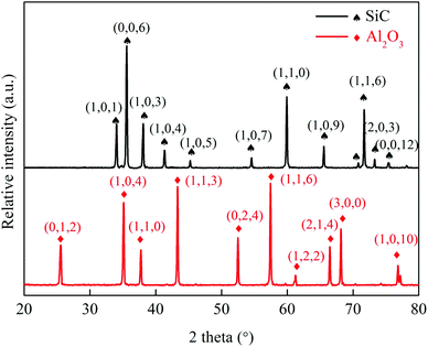 | ||
| Fig. 3 XRD patterns of Al2O3 hollow fiber membrane sintered at 1500 °C and SiC hollow fiber membrane sintered at 2050 °C. | ||
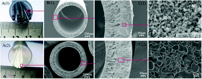
The colors of the SiC and Al2O3 hollow fiber membranes were seen in Fig. 4A, the SiC hollow fiber membrane was black, and the Al2O3 hollow fiber membrane was white. Fig. 4B shows the digital image of the prepared SiC and Al2O3 hollow fiber membranes in well-shaped hollow fiber configurations. The outer and inner diameters (OD/ID) (measured using Digital Microscopy Image Analyzer (DMIA) software) of the sintered SiC and Al2O3 hollow fiber membrane were measured at approximately 2.0 mm/1.7 mm and 2.5 mm/2.0 mm, the wall thickness of the two hollow fiber membrane was 0.3 mm and 0.5 mm respectively. The wall thickness of the two hollow fiber was much smaller than that of the ceramic tube membrane (1.5 mm),33 resulting in a high membrane area per volume and thin thickness, which would be beneficial to improve the permeation flux through the hollow fiber membranes. As shown, the hollow fiber membranes possessed an asymmetric structure (Fig. 4C), sponge-like structure in the middle, sandwiched by a finger-like structure near the outer and inner walls. The finger-like layer extends from the inner surface across approximately 43% of the fiber, but layer length at the outer surface has been greatly reduced to 24%. A sponge-like region occupying approximately 33% of the fiber was present between the inner and outer finger-like voids. The larger lumen of the membrane was favorable to the fluid flow inside the lumen with less resistance.34 From a close examination at the sponge-like structure region, as shown in Fig. 4D at high magnification, the surface of the SiC and Al2O3 hollow fiber membrane, packed by micrometer-sized SiC and Al2O3 particle, was uniform and smooth. The three point bending strength of the SiC hollow fiber membrane sintered at 1800 °C was 88.2 ± 2.5 MPa, which was comparative to the strength (85.8 ± 3.1 MPa) of Al2O3 hollow fiber sintered at 1500 °C in our previous study.32 But the mechanical strength of the hollow fiber sintered at 1800 °C was lower compared to the strength of the tube, in order to impart the fiber with sufficient mechanical strength for practical applications, the 2050 °C calcination temperature was applied to obtain to a higher three point bending strength, which was 102.3 ± 6.7 MPa.
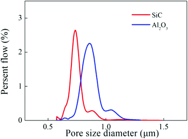
The pore size distributions of the membranes were shown in Fig. 5. It was observed that the two hollow fiber membranes possessed a uniform and narrow pore size distribution, meanwhile, the average pore size of the SiC and Al2O3 hollow fiber membranes were found to be 0.71 μm and 0.82 μm (Fig. 5).
3.2 Hollow fiber membrane surface properties
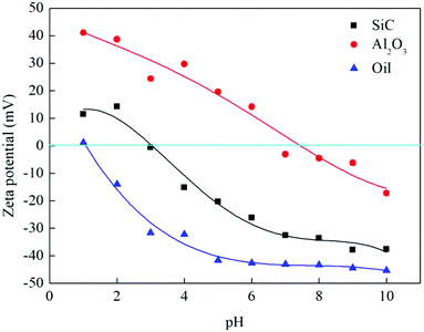
Surface properties were characterized in terms of surface charge, surface hydroxyl groups and hydrophilicity.At pH 6.5 (the pH of the emulsions) of the experiments, SiC hollow fiber membranes were negatively charged, whereas Al2O3 hollow fiber membranes were positively charged, oil droplets were negatively charged (Fig. 6), electrostatic repulsion between oil droplets and the SiC hollow fiber membrane surface would occur, while electrostatic attraction would exist between oil droplets and the Al2O3 hollow fiber membrane surface. The SiC hollow fiber membrane was expected to be excellent in antifouling ability due to its low isoelectric point (pH = 2.9). Hence, it can be inferred that SiC hollow fiber membrane can reduce the adsorption of undesired oil on the membrane surfaces and enhance the flux via reducing membrane fouling.
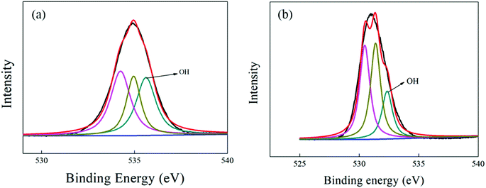 | ||
| Fig. 7 XPS depth profile spectra of the O-1s peaks for the surface of SiC hollow fiber membrane (a) and Al2O3 hollow fiber membrane (b). | ||
For the Al2O3 hollow fiber membrane, via quantification of O 1s peak, the content of contained surface OH- groups was estimated to be 11.6%. By comparison, a substantial increase in surface –OH groups amount was achieved for SiC hollow fiber membranes' surface (20.1%), which might be due to the presence of more adsorbed water molecules from the atmospheric environment, as the top-layer of the SiC hollow fiber membrane was very hydrophilic.16,37 Therefore, the surface OH- groups of SiC hollow fiber membrane probably tend to interact strongly with water molecules through a hydrogen bond, whereas those of the Al2O3 hollow fiber membrane would be significantly less hydrophilic. This hypothesis will be confirmed in the following hydrophilicity test.
3.3 Membrane separation of O/W emulsions
The photographs of the O/W emulsions and the collected permeate separated by the SiC hollow fiber membranes were shown in Fig. 8. The O/W emulsions were milky white because of the light scattering by oil spheres. The collected permeate was clear and transparent, as shown in the optical microscopy images, no obvious droplets could be observed in the filtrates, indicating that the large oil droplets were effectively cut off. The size distribution of the oil droplets in the O/W emulsions was at approximately 1.36 μm, and the pore size of the SiC hollow fiber membranes (0.71 μm) was very small compared to the size of oil. The results indicated that the SiC hollow fiber membranes fabricated in this study could separate O/W emulsions effectively through a sieving mechanism. | ||
| Fig. 8 Photographs and optical microscopy images of O/W emulsions (a) and the permeate (b) separated by the SiC hollow fiber membranes. | ||
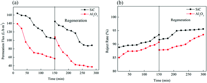
The permeabilities of the O/W emulsions using the two hollow fiber membranes were investigated as illustrated in Fig. 9. The permeation flux of the SiC hollow fiber membrane was 163.9 L h−1 m−2, which was higher compared to the Al2O3 hollow fiber membrane of 139.4 L h−1 m−2 at the beginning of the experiment. The permeation flux of the SiC hollow fiber membrane was 103.9 L h−1 m−2 after 150 min operation, which was also higher than the Al2O3 hollow fiber membrane's permeation flux of 57.1 L h−1 m−2. As shown in Fig. 9, the two membranes all suffered a permeate-flux decline of different extent during filtration, which can be ascribed to membrane fouling. The fouling of the two hollow fiber membranes was typically formed by oil droplets present in the O/W emulsions, the average particle size of the oil was at approximately 1.36 μm, a small fraction of the particle size of the oil droplets was smaller than 1.36 μm, which was also smaller than the pore size of the SiC hollow fiber membranes (0.71 μm), at the beginning of the filtration, the small fraction smaller oil droplets could directly penetrated and stuck inside membrane pores. But the majority of the oil particle cannot permeate through the membranes, and water molecules were allowed to permeate through the membrane pores. However, the SiC hollow fiber membranes showed slower flux reduction ration than the Al2O3 hollow fiber membrane, only ∼36.7% for the SiC hollow fiber membrane, and as high as ∼59.1% for Al2O3 membranes during the 150 min period operation. In this study, the Hermia model39 was employed to identify the fouling mechanism in the filtration of O/W emulsion using the SiC hollow fiber membrane. It is concluded that, at the first stage of membrane filtration process (t < 75 min), the oil droplets adhered easily onto the membrane surface where an intermediate pore blocking occurred, thus decreasing the permeation flux significantly.
The SiC hollow fiber membranes had stronger hydrophilic than the Al2O3 hollow fiber membranes, thus the blocking of membrane pore was avoided because the hydrophilic membrane pores had a high capillary repulsing force to prevent oil droplets from transporting across.13 Moreover, owing to the characteristic negative charge on the material surface and oil particle as described in Section 3.2.1, the ability to reduce deposition of oil foulants was highly increased.40,41 Although there was repulsion between the negatively charged oil droplets and the membrane surface, the tiny oil droplets were more likely to be squeezed into membrane pores under pressure. The penetration of the tiny oil droplets into the membrane pores probably led to membrane fouling. In contrast, the Al2O3 hollow fiber membrane was less hydrophilic, resulting in stronger adsorption of oil droplets on the membrane surface.14
Flux recovery rate (FR) represents the recovery extent of membrane permeability after backwash. Higher FR indicated better antifouling performance and less fouling of the ceramic membrane. These two hollow fiber membranes had different FR after two filtration cycles. For the SiC hollow fiber membrane, it was realized to recover up to 144.7 L h−1 m−2, the FR over 88.3% of the original flux 163.9 L h−1 m−2 by backwashing. This result demonstrated that most of the fouling was removed by a hydraulic backflush. The SiC hollow fiber membrane with alkalescent water soaking can be a promising technology to reduce the fouling of the hollow fiber membranes and enhance membrane cleaning efficiency in the treatment of O/W emulsions. For the Al2O3 hollow fiber membrane, membrane fouling reduced the FR by 77.4%. This was probably because the Al2O3 hollow fiber membrane suffered much more irreversible adsorption fouling than the hydrophilic SiC hollow fiber membrane. This fact again confirmed that the hydrophilicity was a more significant factor influencing the membrane fouling tendency of the membrane in O/W emulsions treatment. This could also be seen as a confirmation of the hypothesis that the SiC hollow fiber membranes with the stronger hydrophilicity had higher water flux and the better anti-fouling property.19,42
Fig. 9 also shows the variation of the oil rejection rate using the two hollow fiber membranes. As shown in Fig. 9, 90.7% of the oil rejection rate was obtained by positively charged Al2O3 hollow fiber membrane, whereas the rejection rate was 93.5% of the negatively charged SiC membranes. These results indicated a higher oil rejection for the SiC hollow fiber membrane compared with that of the Al2O3 hollow fiber membrane in the whole process. In general, oil rejection can be enhanced if the membrane was oppositely charged. Therefore, the produced hydrophilic SiC hollow fiber membranes, which exhibited excellent permeability and high oil rejection, can be suggested for O/W emulsions treatment. When compared with reported data in literatures in Table 1.2,14,19,43 It shows that SiC hollow fiber membrane shows superior results, which has the compared rejection rate, along with the highest flux.
| Membrane | Performance | Ref. | ||||
|---|---|---|---|---|---|---|
| Material | Pore size | Water contact angles | Configuration | Normalized flux (L h−1 m−2 bar−1) | Rd (%) | |
| SiC | 0.71 | 11 | Hollow fiber | 654 | 93.5 | This work |
| SiC | 0.25 | — | Tubular | 200 | — | 19 |
| Si3N4 | 0.68 | — | Hollow fiber | 260 | 91 | 39 |
| TiO2–mullite | 0.11 | 11 | Hollow fiber | 150 | 97 | 2 |
| TiO2–Al2O3 | 6 | 8 | Tubular | 320 | >99 | 14 |
4. Conclusion
A combined induced phase inversion-sintering technique was used for fabricating SiC and Al2O3 hollow fiber membranes. Pore size measurements showed that the pore size of the SiC and Al2O3 hollow fiber membranes were 0.71 μm and 0.82 μm respectively, which was similar to each other. The SiC hollow fiber membranes were more hydrophilic due to the higher surface site density of surface –OH group and lower water contact angle than the Al2O3 hollow fiber membrane. The filtration efficiency of the O/W emulsions results showed that the more hydrophilic SiC hollow fiber membranes contributed to repel oil droplets from adhering to membrane surface, thus to weaken membrane fouling, the permeation flux of the SiC hollow fiber membrane (163.9 L h−1 m−2) was higher compared to the Al2O3 hollow fiber membrane (139.4 L h−1 m−2) at the beginning of the experiment. Dilute NaOH solution backwashing was used to effectively accomplish SiC hollow fiber membranes regeneration (∼88.3% flux recovery rate). It was indicated that the SiC hollow fiber membranes with the stronger hydrophilicity had higher water flux and the better anti-fouling property owing to electrostatic repulsion to the oil during separation treatment of O/W emulsions.Conflicts of interest
There are no conflicts to declare.Acknowledgements
This work was financially supported by the Science Research Fund of Wuhan Institute of Technology (Grant No. 18QD06) and Project of Technology Innovation in Hubei Province (Grant No. 2016ACA161).References
- M. Hengyang, Q. Minghui, B. Jiawei, C. Xianfu, V. Henk and F. Yiqun, ACS Appl. Mater. Interfaces, 2018, 10, 18093–18103 CrossRef PubMed.
- L. Zhu, X. Dong, M. Xu, F. Yang, M. D. Guiver and Y. Dong, J. Membr. Sci., 2019, 582, 140–150 CrossRef CAS.
- Y. Yang, H. Wang, J. Li, B. He, T. Wang and S. Liao, Environ. Sci. Technol., 2012, 46, 6815–6821 CrossRef CAS PubMed.
- Y. Si and Z. Guo, Chem. Lett., 2015, 7, 874–883 CrossRef.
- M. Padaki, R. Murali, M. Abdullah, N. Misdan, A. Moslehyani, M. Kassim, N. Hilal and A. Ismail, Desalination, 2015, 357, 197–207 CrossRef CAS.
- S. Hosseinabadi, M. Reza Sebzari, M. Hemati, F. Rekabdar and T. Mohammadi, Desalination, 2011, 1–3, 222–228 Search PubMed.
- M. C. Fraga, S. Sanches, V. J. Pereira, J. G. Crespo, L. Yuan, J. Marcher, M. V. M. de Yuso, E. Rodríguez-Castellón and J. Benavente, J. Eur. Ceram. Soc., 2017, 37, 899–905 CrossRef CAS.
- H. Abadikhah, J.-W. Wang, X. Xu and S. Agathopoulos, J. Water Process. Eng., 2019, 29, 100799 CrossRef.
- A. Lee, J. W. Elam and S. B. Darling, Environ. Sci.: Water Res. Technol., 2016, 2, 17–42 RSC.
- X. Hu, Y. Yu, J. Zhou, Y. Wang, J. Liang, X. Zhang, Q. Chang and L. Song, J. Membr. Sci., 2015, 476, 200–204 CrossRef CAS.
- F. L. Hua, Y. F. Tsang, Y. J. Wang, S. Y. Chan, H. Chua and S. N. Sin, Chem. Eng. J., 2006, 128, 169–175 CrossRef.
- J.-E. Zhou, Q. Chang, Y. Wang, J. Wang and G. Meng, Sep. Purif. Technol., 2010, 75, 243–248 CrossRef CAS.
- L. Zhu, M. Chen, Y. Dong, C. Y. Tang, A. Huang and L. Li, Water Res., 2016, 90, 277–285 CrossRef CAS.
- Q. Chang, J.-E. Zhou, Y. Wang, J. Liang, X. Zhang, S. Cerneaux, X. Wang, Z. Zhu and Y. Dong, J. Membr. Sci., 2014, 456, 128–133 CrossRef CAS.
- D. Lu, T. Zhang and J. Ma, Environ. Sci. Technol., 2015, 49, 4235–4244 CrossRef CAS PubMed.
- L. Dongwei, Z. Tao, G. Leo, M. Jun and C. Jean-Philippe, Environ. Sci. Technol., 2016, 50, 4668–4674 CrossRef PubMed.
- W. Deng, X. Yu, M. Sahimi and T. T. Tsotsis, J. Membr. Sci., 2014, 451, 192–204 CrossRef CAS.
- M. C. Fraga, S. Sanches, V. J. Pereira, J. G. Crespo, L. Yuan, J. Marcher, M. V. M. d. Yuso, E. Rodríguez-Castellón and J. Benavente, J. Eur. Ceram. Soc., 2017, 37, 899–905 CrossRef CAS.
- B. Hofs, J. Ogier, D. Vries, E. F. Beerendonk and E. R. Cornelissen, Sep. Purif. Technol., 2011, 79, 365–374 CrossRef CAS.
- S. Chang Kim, H.-J. Yeom, Y.-W. Kim, I.-H. Song and J.-H. Ha, Int. J. Appl. Ceram. Technol., 2017, 14, 692–702 CrossRef.
- M. Fukushima, Y. Zhou, Y.-I. Yoshizawa and K. Hirao, J. Eur. Ceram. Soc., 2008, 28, 1043–1048 CrossRef CAS.
- Y. Zhou, M. Fukushima, H. Miyazaki, Y.-I. Yoshizawa, K. Hirao, Y. Iwamoto and K. Sato, J. Membr. Sci., 2011, 369, 112–118 CrossRef CAS.
- G. Xu, K. Wang, Z. Zhong, C.-S. Chen, P. Webley and H. Wang, J. Mater. Chem. A, 2014, 2, 5841–5846 RSC.
- H. Abadikhah, C.-N. Zou, Y.-Z. Hao, J.-W. Wang, L. Lin, S. Khan, X. Xu, C.-S. Chen and S. Agathopoulos, J. Eur. Ceram. Soc., 2018, 38, 4384–4394 CrossRef CAS.
- P. D. Wit, E. J. Kappert, T. Lohaus, M. Wessling, A. Nijmeijer and N. E. Benes, J. Membr. Sci., 2015, 475, 480–487 CrossRef.
- B. F. K. Kingsbury and K. Li, J. Membr. Sci., 2009, 328, 134–140 CrossRef CAS.
- S. M. Liu and K. Li, J. Membr. Sci., 2003, 218, 269–277 CrossRef CAS.
- X. G. Li, H. T. Shao, H. Bai, M. R. Huang and W. Zhang, J. Appl. Polym. Sci., 2003, 90, 3631–3637 CrossRef CAS.
- Y. K. Du, P. Yang, Z. G. Mou, N. P. Hua and L. Jiang, J. Appl. Polym. Sci., 2005, 99(1), 23–26 CrossRef.
- T. Narushima, T. Goto, T. Hirai and Y. Iguchi, Mater. Trans. JIM, 1997, 38, 821–835 CrossRef CAS.
- G. Chen, H. Qi, W. Xing and N. Xu, J. Membr. Sci., 2008, 318, 38–44 CrossRef CAS.
- L. Zhu, J. Ji, S. Wang, C. Xu, K. Yang and M. Xu, Chemosphere, 2018, 206, 278–284 CrossRef CAS.
- X. Tan, S. Liu and K. Li, J. Membr. Sci., 2001, 188, 87–95 CrossRef CAS.
- R. Wang, L. Shi, C. Y. Tang, S. Chou, C. Qiu and A. G. Fane, J. Membr. Sci., 2010, 355, 158–167 CrossRef CAS.
- J. Binner and Y. Zhang, J. Mater. Sci. Lett., 2001, 20, 123–126 CrossRef CAS.
- X. Ma, C. Pengli, M. Zhou, Z. Zhong, F. Zhang and W. Xing, Ind. Eng. Chem. Res., 2017, 56, 7070–7079 CrossRef CAS.
- M. Takeuchi, G. Martra, S. Coluccia and M. Anpo, J. Phys. Chem. B, 2005, 109, 7387–7391 CrossRef CAS PubMed.
- S. J. Oh, N. Kim and Y. T. Lee, J. Membr. Sci., 2009, 345, 13–20 CrossRef CAS.
- H. Huang, T. A. Young and J. G. Jacangelo, Environ. Sci. Technol., 2008, 42, 714–720 CrossRef CAS PubMed.
- B. P. Singh, J. Jena, L. Besra and S. Bhattacharjee, J. Nanopart. Res., 2007, 9, 797–806 CrossRef CAS.
- S. Z. A. Bukhari, J.-H. Ha, J. Lee and I.-H. Song, J. Eur. Ceram. Soc., 2018, 38, 1711–1719 CrossRef CAS.
- H. Huang, T. Young and J. G. Jacangelo, J. Membr. Sci., 2009, 334, 1–8 CrossRef CAS.
- H. Abadikhah, C.-N. Zou, Y.-Z. Hao, J.-W. Wang, L. Lin, S. A. Khan, X. Xu, C.-S. Chen and S. Agathopoulos, J. Eur. Ceram. Soc., 2018, 38, 4384–4394 CrossRef CAS.
| This journal is © The Royal Society of Chemistry 2020 |

