
Ultrathin MnO2 nanoflakes grown on N-doped hollow carbon spheres for high-performance aqueous zinc ion batteries†
Linlin
Chen
ab,
Zhanhong
Yang
 *a,
Fan
Cui
ab,
Jinlei
Meng
ab,
Yinan
Jiang
ab,
Jun
Long
ab and
Xiao
Zeng
ab
*a,
Fan
Cui
ab,
Jinlei
Meng
ab,
Yinan
Jiang
ab,
Jun
Long
ab and
Xiao
Zeng
ab
aHunan Province Key Laboratory of Chemical Power Source, College of Chemistry and Chemical Engineering, Central South University, Changsha, 410083, China. E-mail: zhyangcsu611@163.com
bInnovation Base of Energy and Chemical Materials for Graduate Students Training, Central South University, Changsha, 410083, China
First published on 18th November 2019
Abstract
The use of MnO2 as a promising cathode material for aqueous zinc ion batteries (AZIBs) remains challenging, because its inherent poor electrical conductivity and huge volume changes lead to a fast capacity decay, short cycle life, and sluggish electrode kinetics. In this study, ultrathin MnO2 nanoflakes grown on N-doped hollow carbon spheres (defined as MnO2–NHCSs) were prepared via a simple solution-phase route and subsequent hydrothermal process, and then evaluated for their potential as a cathode for AZIBs. Ultrathin MnO2 nanoflakes decorated on NHCSs endow the overall electrode with abundant exposed active sites and excellent electrical conductivity, which could buffer the volumetric expansion and facilitate the charge-transfer kinetics. Owing to these favorable structural characteristics, the as-synthesized MnO2–NHCS composite can display a high discharge capacity of 349 mA h g−1 at 0.1 A g−1 after 80 cycles. Significantly, ultra-stable long-term cycling performance of 100 mA h g−1 with a superior capacity retention of 78.7% is achieved after 2000 cycles at 2.0 A g−1. Such notable electrochemical properties of MnO2–NHCSs are demonstrated to be superior to that of pure MnO2 hollow spheres (MnO2-HSs) and other previously reported manganese-based oxide cathodes, which is promising for practical applications.
1. Introduction
Aqueous zinc-based batteries have shown remarkable application prospects in the field of large-scale energy storage owing to their merits of low cost, environmental benignness, low safety risk, high ionic conductivity, and high power capability. Traditional zinc-based batteries, including Zn–Mn, Zn–Ni, Zn–Ag and Zn–Air, are mostly assembled with strongly alkaline KOH or NaOH solution as an electrolyte.1,2 However, the zinc electrodes suffer from serious corrosion and passivation under these strong alkaline conditions.3 What is more serious is the generation of zinc dendrites and irreversible discharge products (such as ZnO, Zn(OH)2, etc.), which makes the cycling stability of the electrodes unsatisfactory. In 2011, Kang et al.4 studied the Zn–MnO2 battery systems by replacing alkaline electrolyte with weakly acidic ZnSO4 aqueous solution, and for the first time proposed the concept of aqueous zinc ion batteries (AZIBs). As expected, the formation of zinc dendrites is greatly suppressed, and the safety and cycle life of the assembled batteries is effectively improved. However, research on AZIBs is still limited by the development of appropriate host materials that can offer high specific capacity and outstanding structural stability upon repeated insertion/extraction of guest ions.5As the earliest studied insertion host for AZIBs, MnO2 displays a relatively high open-circuit voltage of about 1.4–1.5 V, and illustrates outstanding specific capacity and energy density.6,7 However, it suffers from poor rate capability and short cycle life owing to its inherent poor conductivity and huge volume changes upon charging and discharging, which hinders its actual application to some extent.8 Generally, the large volume variation of MnO2 is closely related to the Zn2+ insertion/extraction or phase transitions with cycling. For example, the orthorhombic unit cell of a mesoporous γ-MnO2 phase was expanded by 9.21% after being fully discharged due to Zn-insertion;9 the porous structure of the MnO2/CNT hybrid cathode prepared by Zhang et al.10 was destroyed after 1000 repeated charge and discharge cycles owing to the fast and large volume variation induced by Zn2+ insertion and extraction at high current densities, resulting in a decline in capacity. In order to settle these above issues and harvest high-performance electrode materials, many scholars have carried out a lot of research. Liang's group11 compared the volume charges of carbon coated MnO and carbon free MnO under different cycle times. It was found that the change of unit cell parameters of carbon-coated MnO is very inconspicuous, implying that the carbon coating can effectively buffer the volume variation during Zn2+ insertion/extraction. Furthermore, vanadium-doped MnO2 nanoparticles reported by Alfaruqi et al.12 were demonstrated to have a significant improvement in the electrochemical zinc-storage properties, because the introduction of V-ions into the MnO2 framework can not only enhance the electrical conductivity, but also lead to anisotropic extension of the MnO2 lattice. Nevertheless, the cycling stability is still very unsatisfactory, and only a specific discharge capacity of 131 mA h g−1 can be preserved with a retention rate of 49.2% after 100 cycles at 66 mA g−1. In addition, a graphene scroll-coated α-MnO2 composite was synthesized and investigated as a high performance positive material for AZIBs,13 which shows a high capacity of 382.2 mA h g−1 at 0.3 A g−1. Although the cycling performances have been obviously improved, the poor electrochemical kinetics of MnO2 is still a great challenge. To the best of our knowledge, the electrochemical properties of metal oxide electrodes for Na+, Li+, and K+ batteries can be obviously improved by utilizing various effective strategies such as constructing porous and micro & nano-structures, and carbon coating, etc. In particular, nanostructures with hollow interiors are characterized by highly accessible surface area that can enable sufficient contact between the electrode material and electrolyte and provide big cavities for alleviating structural stresses caused by ion insertion/deintercalation or surface Faraday reaction.14,15 Furthermore, composites with carbon-based materials are also favored by many scholars, especially nitrogen-doped carbon, which can greatly improve the reactivity and electrical conductivity of electrode materials by creating extrinsic defects.16 However, as far as we know, the combination of hollow structure and highly conductive N-doped carbon for constructing a promising MnO2 cathode of AZIBs has not been reported to date.
In this study, we demonstrate the construction of ultrathin MnO2 nanoflakes grown on the surface of N-doped hollow carbon spheres (NHCSs) as a stable and high-rate cathode material for AZIBs. NHCSs as a growth substrate can effectively promote the uniform distribution of active MnO2 nanosheets, increase the total contact area at the electrode–electrolyte interface, and expose more active sites for the maximum utilization of the active ingredient. The combination of NHCSs also significantly enhances the conductivity of the positive electrode. Meanwhile, the MnO2–NHCSs hybrid with a hollow structure possesses a large specific surface area, a large cavity volume, and short ion diffusion path, which is kinetically favorable for ion and electron transport. When used as a cathode for AZIBs, the MnO2–NHCS electrode displays a promising electrochemical performance with good rate ability and excellent cycling stability, which presents a high specific discharge capacity of 349 mA h g−1 at 0.1 A g−1 after 80 cycles, and a capacity of 100 mA h g−1 with a superior retention of 78.7% after 2000 cycles at a high rate of 2.0 A g−1. This outstanding electrochemical performance of MnO2–NHCSs is superior to pure MnO2 hollow spheres (MnO2-HSs) and other previously reported manganese-based oxide cathodes. The presented strategy sheds light on the further development of appealing cathode materials for AZIBs and other energy storage systems.
2. Experimental section
2.1. Preparations
2.2. Material characterization
Crystallographic phases of the as-fabricated product and cycled electrodes were studied by using PANalytical Empyrean XRD system with Cu Kα radiation. The surface element valence states of samples were examined using a Phi Quantum 2000 spectrophotometer with Al Kα radiation. The cycled electrodes recorded for ex situ XRD and XPS analysis were prepared as follows: (i) it was charged or discharged with constant current to specific voltages and different cycles; (ii) disassemble the batteries and pick the corresponding cathodes out; (iii) rinse the electrode thoroughly with deionized water after removing the adhered white fibers from it; (iv) dry under vacuum for measurement. Thermogravimetric analysis (TGA) was conducted on a Netzsch STA 2500 thermal instrument in air. An FEI Helios NanoLab G3 UC scanning electron microscope (SEM) and JEM-2100F transmission electron microscope (TEM) were implemented to analyze the appearance of the as-prepared samples. Specific surface area and pore structure characteristics of the samples were tested by N2 adsorption/desorption isotherms at −196 °C on a Mike ASAP 2460 analyzer.2.3. Electrochemical measurements
To investigate the effects of carbon decoration and microstructure on the electrode performance of MnO2 for AZIBs, CR 2025 coin batteries were constructed by using MnO2–NHCSs or MnO2-HSs as a cathode, metallic zinc foil as an anode, waterman GF/D glass microfiber filters as the separator, and a mixed aqueous solution containing 3 M ZnSO4 and 0.15 M MnSO4 as an electrolyte (pH = 4.3). The cathode was fabricated by mixing active material, conductive agent (super P) and polytetrafluoroethylene binder (PTFE, Daikin D210C, 5% of emulsion in water, average particle size 181 nm) in a weight proportion of 7![[thin space (1/6-em)]](https://www.rsc.org/images/entities/char_2009.gif) :2:1. After sufficient grinding, the mixed slurry was made into a film and cut into several ∅ 10 mm coins. Lastly, these coins were pressed onto current collector titanium meshes that had been washed several times with acetone, absolute ethanol and deionized water before use, and dried under vacuum at 65 °C overnight. The mass loading of the active material is around 1.3–1.6 mg cm−2. Galvanostatic charging and discharging (GCD) experiments were performed on a Neware-battery testing system within the potential window of 1.0–1.85 V (versus Zn/Zn2+). Besides, cyclic voltammetry (CV) and electrochemical impedance spectroscopy (EIS) measurements were conducted using an electrochemical workstation (CHI 660E). The EIS plots were recorded at a frequency range of 10−2 to 105 Hz with an amplitude of 5 mV.
:2:1. After sufficient grinding, the mixed slurry was made into a film and cut into several ∅ 10 mm coins. Lastly, these coins were pressed onto current collector titanium meshes that had been washed several times with acetone, absolute ethanol and deionized water before use, and dried under vacuum at 65 °C overnight. The mass loading of the active material is around 1.3–1.6 mg cm−2. Galvanostatic charging and discharging (GCD) experiments were performed on a Neware-battery testing system within the potential window of 1.0–1.85 V (versus Zn/Zn2+). Besides, cyclic voltammetry (CV) and electrochemical impedance spectroscopy (EIS) measurements were conducted using an electrochemical workstation (CHI 660E). The EIS plots were recorded at a frequency range of 10−2 to 105 Hz with an amplitude of 5 mV.
3. Results and discussion
The typical procedure for the fabrication of MnO2–NHCSs is schematically illustrated in Fig. S1 (ESI†). Firstly, TEOS as a structure-assistant agent is first hydrolyzed to form SiO2 cores in an appropriate amount of ammonia aqueous solution, and then PDA as a carbon precursor derived from the polymerization of DA is deposited on the outer surface of the silicon cores, resulting in a core–shell structure of SiO2@PDA.17 Second, the precursor is subjected to heat treatment and HF leaching to carbonize the PDA polymer and remove the silicon template to get the NHCSs. Finally, MnO2 nanoflakes are grown on the surface of NHCSs by a redox reaction and an in situ self-limiting deposition method under hydrothermal conditions.19 The morphologies and microstructures of the as-prepared NHCS, MnO2–NHCS, and MnO2-HS samples were characterized by SEM and TEM. It can be seen from Fig. 1a that the NHCSs appeared in uniform spherical shape with relatively smooth surface. The TEM images (Fig. 1b) present the typical hollow nanostructure feature of these spheres with an average diameter of about 250 nm and a shell thickness of 20 nm. The hollow carbon spheres with large cavity can be used as a good substrate for the growth of MnO2. Fig. 1c shows the SEM photograph of the MnO2–NHCS composites, from which flower-like spherical morphology assembled by numerous interconnected ultrathin MnO2 nanoflakes is observed. In addition, it can be clearly seen that these nanosheets grow vertically on the outer surface of NHCSs (Fig. 1d), and their thickness is very thin, which is conducive to providing sufficient active sites for electrochemical reactions. Fig. S2a and b (ESI†) show the high-resolution TEM photographs of the MnO2–NHCS sample. It can be noticed that the clear lattice fringes with interplanar distance of 0.70 and 0.24 nm can match well with the (001) and (111) lattice planes of birnessite-type MnO2. The selected area electron diffraction (SAED) pattern (Fig. S2c, ESI†) indicates its polycrystalline nature and poor crystallinity. For convenience of comparison, the microstructure of MnO2-HSs is also analyzed, whose growth substrate is uniform SiO2 spheres with a diameter of about 280 nm (Fig. S3, ESI†). As demonstrated in Fig. 1e and f, the MnO2-HS samples exhibit a similar morphology to that of MnO2-NHCS, except for the inner carbon core displayed in the TEM image. Meanwhile, the surface MnO2 nanosheets grow larger and irregular compared to MnO2-NHCS. | ||
| Fig. 1 SEM and TEM photographs of (a and b) NHCS, (c and d) MnO2-NHCS, and (e and f) MnO2-HS samples. | ||
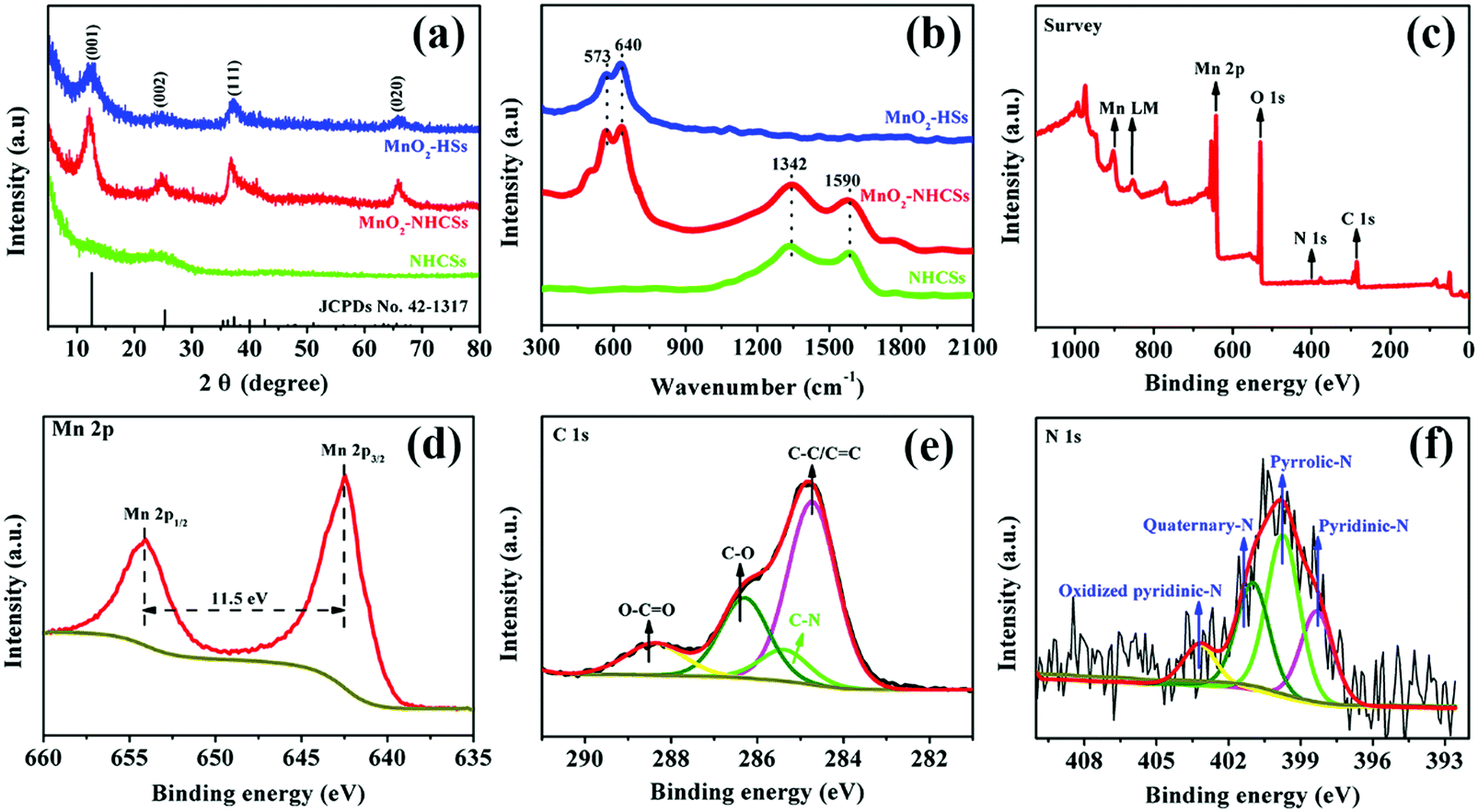
The XRD patterns of the as-prepared materials are displayed in Fig. 2a. In particular, a broad X-ray diffraction peak of NHCSs at 2θ values of 25.2° can be indexed to the (002) Bragg's reflection plane of the highly graphitized carbon.20,21 For MnO2–NHCS and MnO2-HS samples, the four characteristic peaks at 12.6°, 24.9°, 37.1°, and 65.5° correspond well with the (001), (002), (111), and (020) faces of birnessite-type MnO2 (JCPDs No. 42-1317) with space group C2/m (a monoclinic unit cell with a = 5.15 Å, b = 2.844 Å, c = 7.159 Å). The crystal structure of 2D layered birnessite-like MnO2 is constructed by layers of edge-sharing MnO6 octahedra, and the interlayer space is typically filled with a certain number of crystallographically bonded water molecules and foreign cations, which play a role in stabilizing the layered structure and balancing the charges.22 The large interlayer distance along the 001 diffraction direction is theoretically advantageous for the storage and transportation of zinc ions. Meanwhile, the broadened and weak diffraction peaks reveal a poor crystallization of the obtained MnO2 samples. The Raman spectra of the harvested three samples are displayed in Fig. 2b. For the NHCS sample, two peaks at 1342 and 1590 cm−1 are observed, which can be assigned to the defected or disordered graphitic structure (D band) and the crystallized graphite peak (G band), respectively.23 After the incorporation of MnO2 on NHCSs, the ID/IG values used to analyze the structural defects are slightly increased from 1.02 to 1.08, implying that more structural defects are formed in the hybrids. Besides the Raman response from the carbon components, the peaks at 573 and 640 cm−1 can be ascribed to the typical vibrational results of birnessite-type MnO2 compounds.24 Among those bands, the peak at 573 cm−1 is related to the ν3(Mn–O) stretching vibration in the basal plane of [MnO6] sheets; while the peak at 640 cm−1 is attributed to the ν2(Mn–O) symmetric stretching vibration of the [MnO6] octahedron.25,26 The surface elemental compositions and valence states of MnO2–NHCSs were investigated through XPS characterization. From the XPS survey spectrum shown in Fig. 2c, the main peaks corresponding to Mn, O, C, and N elements are observed. Fig. 2d displays the high resolution Mn2p XPS spectrum, in which two peaks at 642.4 and 653.9 eV are indicative of Mn 2p1/2 and Mn 2p3/2. And the energy difference of 11.5 eV between these two bands is detected, displaying good consistency with the location of the tetravalent manganese Mn4+.27 The C1s core level spectrum presented in Fig. 2e can be deconvoluted into four components, which are C–C/C![[double bond, length as m-dash]](https://www.rsc.org/images/entities/char_e001.gif) C (284.7 eV), C–N (285.4 eV), C–O (286.3 eV) and O–CO (288.4 eV).28,29 It is noteworthy that the existence of a C–N bond indicates successful introduction of an N element to the carbon material using aqueous ammonia solution. As for the N 1s core-level spectrum shown in Fig. 2f, four types of nitrogen chemical states that arise from pyridinic-N (398.3 eV), pyrrolic-N (399.8 eV), quaternary-N (400.9 eV), and oxidized pyridinic-N (403.2 eV) are noticed.27 It is generally believed that nitrogen doping can create some defects, provide conjugated electrons, and further enhance the electrical conductivity of electrode materials.
C (284.7 eV), C–N (285.4 eV), C–O (286.3 eV) and O–CO (288.4 eV).28,29 It is noteworthy that the existence of a C–N bond indicates successful introduction of an N element to the carbon material using aqueous ammonia solution. As for the N 1s core-level spectrum shown in Fig. 2f, four types of nitrogen chemical states that arise from pyridinic-N (398.3 eV), pyrrolic-N (399.8 eV), quaternary-N (400.9 eV), and oxidized pyridinic-N (403.2 eV) are noticed.27 It is generally believed that nitrogen doping can create some defects, provide conjugated electrons, and further enhance the electrical conductivity of electrode materials.
 | ||
| Fig. 2 (a) XRD patterns and (b) Raman spectra of NHCSs, MnO2–NHCSs, and MnO2-HSs. (c) XPS full spectrum of MnO2–NHCSs. (d, e, and f) The core-level XPS spectra for Mn 2p, C 1s, and N 1s of MnO2–NHCSs, respectively. | ||
In order to gain an intuitive vision into the pore structure of MnO2–NHCS and MnO2-HS samples, the N2 adsorption/desorption isotherms and corresponding pore size distribution profiles were studied, as presented in Fig. 3. Based on the IUPAC definition, both samples exhibit a typical type-IV adsorption isotherm with H3 hysteresis loop. This kind of hysteresis loop is generally considered to be the feature of slit-shaped mesopores, which arise from the vertical growth of numerous MnO2 nanoflakes.3,30 According to the Brunauer–Emmett–Teller (BET) and Barrett–Joyner–Halenda (BJH) equations, the calculated parameters such as specific surface area, pore volume and average pore size of these two samples are recorded in Table S1. The MnO2–NHCS sample exhibits a higher surface area of 213.12 m2 g−1 relative to that of MnO2-HSs (141.24 m2 g−1). Meanwhile, the BJH pore size distribution (inset of Fig. 3a and b) reveals that the pore widths of both samples vary over a wide range, featuring a hierarchical pore structure. Among them, the average pore size of MnO2–NHCSs is relatively small and uniformly distributed. A large specific surface area and suitable hierarchical pore distribution can not only decrease the diffusion path length of ions and thus facilitate the infiltration and migration of electrolyte ions throughout the whole electrode materials, but also boost the homogeneous accumulation of electrical charges at the electrode–electrolyte interface.15,27 This structural architecture is highly beneficial for electrochemical reactions. Thermogravimetric analysis (TGA) was employed to evaluate the thermal stability of MnO2–NHCSs and MnO2-HSs, and the results indicate that the mass ratio of NHCSs in the MnO2–NHCS hybrid is about 10.2 wt% (Fig. S4, ESI†).
 | ||
| Fig. 3 N2 adsorption–desorption isotherms and the corresponding pore size distribution profiles (inset) of (a) MnO2–NHCSs and (b) MnO2-HSs. | ||
Type 2025 coin batteries were constructed to explore various electrochemical properties. Fig. 4a displays the CV profiles of MnO2–NHCSs at a sweep rate of 0.5 mV s−1 within the voltage window of 1.0–1.85 V. During the first cathodic scan, a strong reduction peak appears at 1.17 V, which is associated with the insertion of Zn2+ and the reduction of Mn4+ to Mn3+/Mn2+ states. Conversely, an oxidation peak located at 1.60 V is observed during the anodic scan, corresponding to the Zn2+ extraction and reinstatement of Mn4+. However, the CV curves in the following cycles are slightly different, with the former cathodic peak shifting toward higher voltage (∼1.25 V) and a new peak appearing at 1.36 V, which is similar to the CV response of other Mn-based electrodes reported in the literature.31 It should be noted that the CV curves coincide well after the first five sweeps, demonstrating good stability and reversibility of the MnO2–NHCS electrode. Fig. 4b compares the CV profiles of MnO2–NHCSs and MnO2-HSs, from which we can see that the MnO2–NHCS electrode exhibits a slightly higher current density and reduced potential separation among the oxidation and reduction peaks compared with that of MnO2-HSs, indicating a substantial improvement of the electrochemical capacitance and reversibility due to the incorporation of NHCSs and favorable structure with high specific surface area and suitable hierarchical pore distribution. Generally, the voltage difference for charging/discharging potential platforms is related to the electrode polarization in the electrochemical reaction processes. As shown in Fig. 4c, the potential differences of MnO2–NHCSs in the first and second plateaus are 95 and 310 mV, respectively, which is lower than that of the MnO2-HSs electrode, further verifying the decrease of electrochemical polarization and the improvement of electrode reversibility. The average discharge and charge voltage of the MnO2–NHCS electrode were calculated to be 1.362 and 1.569 V (Fig. S5, ESI†). The cycling stability of MnO2–NHCSs and MnO2-HSs at 0.1 A g−1 was studied comparatively, as presented in Fig. 4d. The average specific discharge capacity of MnO2–NHCSs during the initial several cycles is about 350 mA h g−1, which is slightly superior to that of MnO2-HSs (330 mA h g−1). However, the electrode with MnO2-HSs suffers from strong capacity fading, and it delivers a discharge capacity of 266 mA h g−1 with about 80.6% capacity retention after 80 cycles, which is obviously not comparable to the MnO2–NHCS electrode (349 mA h g−1 without capacity loss after 80 cycles). In order to get the underlying reasons why the electrochemical behavior of MnO2–NHCSs is more advanced than that of MnO2-HSs, EIS analysis was performed (Fig. 4e). The impedance curves of these two samples are all built up of a semicircle in the high frequency area and an oblique straight line in the low frequency range, wherein the semicircle diameter is considered to be related to the charge transfer impedance (Rct) at the electrolyte/electrode interface. Surprisingly, the Rct value of 612 Ω for MnO2–NHCSs is much lower than that of MnO2-HSs (940 Ω) due to the modification with N-doped carbon, and its Rct values are greatly reduced during the initial first five cycles and is still smaller than that of the pure MnO2 sample (Fig. S6, ESI†), which enables rapid charge transfer within the electrode materials, thus resulting in an improved electrochemical performance. For both samples, the decrease in the charge transfer resistance with initial cycling can be explained by the following: as the cell is cycled, the electrolyte can be sufficiently wetted the previously inaccessible regions in the interior of electrode particles, resulting in an increase of the active surface area available for reaction.32 Meanwhile, the diffusion paths of Zn2+ could be gradually developed with the penetration of an electrolyte, leading to an improvement of the reaction kinetics.33
 | ||
| Fig. 4 (a) CV curves of MnO2–NHCSs at 0.5 mV s−1, (b) comparison of CV profiles of MnO2–NHCSs and MnO2-HSs at 0.5 mV s−1, (c) GCD profiles of MnO2–NHCSs and MnO2-HSs for the 5th cycle, (d) the cycling performance at 0.1 A g−1, (e) Nyquist plots of MnO2–NHCSs and MnO2-HSs, (f) GCD profiles of MnO2–NHCSs under various current rates, (g) rate performance of MnO2–NHCSs and MnO2-HSs, and (h) Ragone plots of MnO2–NHCSs compared with other reported manganese oxide-based electrodes. | ||
Rate performance is of vital importance for practical applications due to the increasing demand for fast charging. So the rate capability of MnO2–NHCSs and MnO2-HSs was studied through charging and discharging under varied current densities from 0.1 to 3.0 A g−1. As observed in Fig. 4g, when cycled at 0.1, 0.3, 0.5, 0.8, 1.0, 1.5, and 2.0 A g−1, the reversible capacities of MnO2–NHCSs are ∼348, 293, 262, 227, 204, 168, and 149 mA h g−1, respectively. Conspicuously, the capacity still remained as high as 127 mA h g−1 at an extremely high current density of 3.0 A g−1. When the current gradually switched back to 0.1 A g−1, the discharge capacity could recover to 318 mA h g−1 with 91.3% capacitance retention undergoing 80 rate cycles, displaying excellent rate performance and fast reaction kinetics. In contrast, the capacities of MnO2-HSs rapidly decreased with increasing current densities, and only 74 mA h g−1 is maintained at a high rate of 3 A g−1. The above results indicate that MnO2–NHCSs have more superior rate performance than MnO2-HSs, which can be explained by the following aspects: (i) the presence of nitrogen-doped carbon spheres as the substrate could effectively enhance the conductivity of electrode materials and thus improve the electron transfer during the redox reaction; (ii) attachment of MnO2 to the carbon sphere skeleton is advantageous for maintaining structural stability such that the electrode can withstand the impact of large currents during cycling. GCD curves of MnO2–NHCSs at different current rates are presented in Fig. 4f. Interestingly, with the increase in current densities, the second discharge platform below 1.3V (demarcation by turning point, see Fig. S7a, ESI†) gradually becomes invisible, and its contribution to the total capacity decreases significantly (Fig. S7b, ESI†), implying that the electrode reaction kinetics in this low discharge plateau region is not as good as that in the upper voltage region. Meanwhile, the battery assembled with our prepared MnO2–NHCSs electrode was able to deliver a maximum energy density of 457 W h kg−1 at a power density of 109 W kg−1, and a maximum power density of 3313 W kg−1 at an energy density of 165 W h kg−1, which outperforms most recently reported manganese oxide-based electrodes, such as C-MnO2,25 ZnMn2O4,34 SSWM@Mn3O4,35 Mn2O3,36 α-MnO2,4 δ-MnO2,37 todorokite,38etc.
The excellent rate performance of the MnO2–NHCS electrode motivated us to further explore the electrochemical reaction kinetics. Fig. 5a displays the CV curves of MnO2–NHCSs at different sweep rates ranging from 0.1 to 1.0 mV s−1. It can be noticed that the shapes of the CV curves are basically the same with the promoted scan rates, except for the increased peak current and peak shift, suggesting good structural stability of the MnO2–NHCS electrode. The electrochemical kinetics can usually be evaluated through the quantitative relationship between the peak intensity in current (i) and the sweeping rates (v).39
| i = avb | (1) |
 | ||
| Fig. 5 (a) CV profiles of MnO2–NHCSs at varied scan rates, (b) the proportion of capacitive contributions at varied scan rates, and (c and d) GITT profiles and the corresponding calculated DZn values during the discharge and charge process. | ||
According to the equation, the b values can be fitted by the linearity of log(i) vs. log(v). A b slope of 0.5 suggests a diffusion-dominated Zn2+ intercalation mechanism, while a b value near to 1.0 illustrates a surface-limited capacitive behavior. As shown in Fig. S8 (ESI†) for the MnO2–NHCS cathode, the b values for peak 1, peak 2, and peak 3 are 0.74, 0.89, and 0.50, respectively, implying that the dual contributions of capacitance and diffusion coexist during the cycling. Among these, the capacitive contribution can be calculated based on eqn (2):
| i = k1v + k2v1/2 | (2) |
The enduring cyclic stability at high rates is of great significance for practical applications. Therefore, the long-term GCD tests for the MnO2–NHCS electrode at a high current density of 1.0 A g−1 were conducted (Fig. 6a). Impressively, the MnO2–NHCS electrode is able to display a reversible capacity of 157 mA h g−1 with a high retention rate of 84.0% after 650 cycles with about 100% coulombic efficiency for all cycles, while the MnO2-HS electrode displays a low capacity of 72 mA h g−1 with about 48.3% capacity retention under identical test conditions, further revealing the outstanding rate capability and superior cycling stability of the as-prepared MnO2–NHCS cathode. In addition, even at 2.0 A g−1 (Fig. 6b), the MnO2–NHCS electrode also illustrates an outstanding reversible capacity as high as 100 mA h g−1 with a superior retention rate of 78.7% after 2000 cycles, which is distinctly higher than that delivered by MnO2-HSs. Meanwhile, it is necessary to point out that the capacity contribution of pure NHCSs throughout the entire charging/discharging process is small and basically negligible (Fig. S11, ESI†). Table S2 (ESI†) compares the electrochemical performance of the MnO2–NHCS electrode with other previously reported manganese-based oxide cathodes, from which we can notice that MnO2–NHCSs demonstrate a superior electrochemical performance, not only in rate capability but also on the basis of cycling stability. The excellent performance of the MnO2–NHCS electrode can be explained by the following key factors: (1) the unique structure features, including large specific surface area and suitable hierarchical mesoporous distribution, can offer reduced lengths for electron transport and ion diffusion, and thus endow more electrochemically active/ion-insertion sites; (2) the N heteroatom doped hollow carbon spheres as a growth substrate can not only enhance the overall electrical conductivity of the electrode material, but also provide good accommodation of the structural strain and effectively ensure the structural stability upon cycling.43 In order to demonstrate whether the electrode can be stable for long-term cycling, the microscopic appearance of the electrode after 100 cycles at 1.0 A g−1 was characterized by SEM. As can be seen from Fig. S12 (ESI†), the nanosphere appearance of the MnO2–NHCS electrode can be basically preserved after cycling, and only a small degree of micro-destruction and collapse of the surface nanosheets is observed. Fig. S13 (ESI†) presents a comparison of the SEM images of the Zn anode before and after cycling. It should be noted that no zinc dendrites were formed after repeated charging/discharging at 1.0 A g−1 for 100 cycles, which is extremely significant for long-term cycle stability. To further illustrate the potential application of this MnO2–NHCS electrode, a flexible battery was constructed with xanthan gum electrolyte (see the ESI,† for details). It is noted from Fig. 6c that the as-fabricated device could deliver a specific energy higher than 200 W h kg−1 at different states such as folding and soaking in water without deteriorating the discharge profile obviously, and it can power a 1.5 V temperature sensor under various conditions.
 | ||
| Fig. 6 The cycling stability of MnO2–NHCSs and MnO2-HSs at high rates of (a) 1.0 A g−1 and (b) 2.0 A g−1. (c) GCD curves of the flexible Zn/MnO2–NHCSs batteries, and the insets show the digital photos of the flexible battery powering a 1.5 V temperature sensor. | ||
In order to reveal the zinc storage mechanism of the MnO2–NHCS electrode, ex situ XRD patterns under different charge/discharge states in the first cycle were investigated, as shown in Fig. S14 (ESI†). During the discharge process, a set of new peaks located at 16.5°, 21.3°, 24.4°, 25.3°, and 33.0° were observed, which can be ascribed to the zinc hydroxide sulfate hydrate ZnSO4[Zn(OH)2]3·5H2O (ZSH, JCPDs 78-0246).41 Meanwhile, the intensity of these newly appeared peaks continuously enhances with the increase of depth of discharge, and then they disappear in the following reverse charge process, indicating a reversible dissolution/precipitation of the ZSH phase. Besides, some small new peaks at 31.8° and 33.5° in the discharged states are attributable to MnOOH (JCPDs 24-0713), and other emerging peaks with 2θ values of 15.4, 27.7, 35.1, and 37.3 can be indexed to the Zn-inserted phases ZnxMnO2.44,45 The formation of ZSH and MnOOH new phases is generally considered to be related to the decomposition of water and the insertion of hydrogen protons. Interestingly, all new phases cannot be detected in the complete charge state, and all characteristic diffraction peaks of MnO2 can be restored to the initial state, demonstrating a reversible zinc storage mechanism involving H+/Zn2+ insertion/extraction processes and the ZSH dissolution/precipitation reaction. In addition, the crystal structure of the MnO2–NHCSs can be well maintained after hundreds of cycles (Fig. S15, ESI†), showing good structural stability. Ex situ XPS analysis of the MnO2–NHCS electrode at fully discharged/charged states was also performed to further reveal the elemental composition and the valence change, as displayed in Fig. S16 (ESI†). In the high resolution Zn 2p spectrum (Fig. S16a, ESI†), two obvious peaks indexed to Zn 2p3/2 (1022.5 eV) and Zn 2p1/2 (1045.5 eV) were noticed when discharging to 1.0 V, further implying the intercalation of zinc ions and the formation of ZSH, being consistent with the ex situ XRD results. However, in the fully charged state, there are still some Zn 2p signals captured that may be caused by incomplete release of inserted Zn2+ from the lattice. Fig. S16b (ESI†) presents the Mn2p core-level XPS spectra. After being fully discharged, Mn4+ is partially reduced to Mn3+ and Mn2+. Conversely, the Mn4+ signal increases accompanied by the Mn2+ signal obviously decreasing after fully recharging; meanwhile, the increase of the Mn valence can be clearly illustrated by the slightly reduced peak energy difference values of Mn 3s for the extraction state (Fig. S16c, ESI†), further confirming the reversible charge transfer in Mn upon cycling.
4. Conclusions
In summary, a novel composite of MnO2–NHCSs with an NHCS core and ultrathin MnO2 nanoflake shell was successfully prepared. NHCSs as the growth matrix can not only effectively prevent aggregation of the MnO2 nanosheets and maximize the exposure of active sites, but also provide a buffer space for the volumetric expansion and resist the strain arising from the repeated discharge–charge processes. Moreover, the presence of NHCSs can significantly improve the electrical conductivity of the composite. When employed as a cathode material for AZIBs, it displays a high specific discharge capacity (349 mA h g−1 at 0.1 A g−1 after 80 cycles) as well as outstanding stable cycling ability (cycling for 2000 cycles with a high retention rate of 78.7% at 2.0 A g−1). In addition, the superior electrode can be extended to the field of flexible batteries. This work might provide a new strategy for exploring high-performance cathode materials with exceptional rate capability and long cycling stability for practical AZIBs and other energy storage systems.Conflicts of interest
There are no conflicts to declare.Acknowledgements
This work was supported by the Natural Science Foundation of China (No. 21371180) and Hunan Provincial Science and Technology Plan Project (No. 2017TP1001).Notes and references
- P. Yu, Y. X. Zeng, H. Z. Zhang, M. H. Yu, Y. X. Tong and X. H. Lu, Small, 2019, 15, 1804760 CrossRef.
- L. T. Ma, Y. W. Zhao, X. X. Ji, J. Zeng, Q. Yang, Y. Guo, Z. D. Huang, X. L. Li, J. Yu and C. Y. Zhi, Adv. Energy Mater., 2019, 9, 1900509 CrossRef.
- L. M. Wang, Z. H. Yang, X. Chen, H. G. Qin and P. Yan, J. Power Sources, 2018, 396, 615–620 CrossRef CAS.
- C. J. Xu, B. H. Li, H. D. Du and F. Y. Kang, Angew. Chem., Int. Ed., 2012, 51, 933–935 CrossRef CAS.
- B. Y. Tang, L. T. Shan, S. Q. Liang and J. Zhou, Energy Environ. Sci., 2019, 12, 3288–3304 RSC.
- M. Song, H. Tan, D. L. Chao and H. J. Fan, Adv. Funct. Mater., 2018, 28, 1802564 CrossRef.
- G. Z. Fang, J. Zhou, A. Q. Pan and S. Q. Liang, ACS Energy Lett., 2018, 3, 2480–2501 CrossRef CAS.
- S. N. Yang, M. S. Zhang, X. W. Wu, X. S. Wu, F. H. Zeng, Y. T. Li, S. Y. Duan, D. H. Fan, Y. Yang and X. M. Wu, J. Electroanal. Chem., 2019, 832, 69–74 CrossRef CAS.
- M. H. Alfaruqi, V. Mathew, J. Gim, S. Kim, J. Song, J. P. Baboo, S. H. Choi and J. Kim, Chem. Mater., 2015, 27, 3609–3620 CrossRef CAS.
- S. Zhang, N. S. Yu, S. Zeng, S. S. Zhou, M. H. Chen, J. T. Di and Q. W. Li, J. Mater. Chem. A, 2018, 6, 12237 RSC.
- C. Y. Zhu, G. Z. Fang, S. Q. Liang, Z. X. Chen, Z. Q. Wang, J. Y. Ma, H. Wang, B. Y. Tang, X. S. Zheng and J. Zhou, Energy Storage Materials, 2019 DOI:10.1016/j.ensm.2019.07.030.
- M. H. Alfaruqi, S. Islam, V. Mathew, J. J. Song, S. J. Kim, D. P. Tung, J. Jo, S. Kim, J. P. Baboo, Z. L. Xiu and J. Kim, Appl. Surf. Sci., 2017, 404, 435–442 CrossRef CAS.
- B. K. Wu, G. B. Zhang, M. Y. Yan, T. F. Xiong, P. He, L. He, X. Xu and L. Q. Mai, Small, 2018, 14, 1703850 CrossRef.
- C. F. Dong, J. W. Liang, Y. Y. He, C. C. Li, X. X. Chen, L. J. Guo, F. Tian, Y. T. Qian and L. Q. Xu, ACS Nano, 2018, 12, 8277–8287 CrossRef CAS.
- C. F. Dong, L. J. Guo, Y. Y. He, L. M. Shang, Y. T. Qian and L. Q. Xu, Nanoscale, 2018, 10, 2804–2811 RSC.
- Y. Q. Fu, Q. L. Wei, G. X. Zhang, X. M. Wang, J. H. Zhang, Y. F. Hu, D. N. Wang, L. Zuin, T. Zhou, Y. C. Wu and S. H. Sun, Adv. Energy Mater., 2018, 8, 1801445 CrossRef.
- C. Liu, J. Wang, J. S. Li, R. Luo, J. Y. Shen, X. Y. Sun, W. Q. Han and L. J. Wang, ACS Appl. Mater. Interfaces, 2015, 7, 18609–18617 CrossRef CAS.
- R. Watanabe, T. Yokoi, E. Kobayashi, Y. Otsuka, A. Shimojima, T. Okubo and T. Tatsumi, J. Colloid Interface Sci., 2011, 360, 1–7 CrossRef CAS.
- H. L. Fan, F. Ran, X. X. Zhang, H. M. Song, X. Q. Niu, L. B. Kong and L. Kang, Nano-Micro Lett., 2015, 7, 59–67 CrossRef CAS.
- C. M. S. Anandhi, S. Premkumar, R. M. Asath, T. Mathavan and A. M. F. Benial, AIP Conf. Proc., 2016, 1728, 020456 CrossRef.
- R. Illathvalappil, L. George and S. Kurungot, ACS Appl. Energy Mater., 2019, 2, 4987–4998 CrossRef CAS.
- D. H. Wang, L. F. Wang, G. J. Liang, H. F. Li, Z. X. Liu, Z. J. Tang, J. B. Liang and C. Y. Zhi, ACS Nano, 2019, 13, 10643–10652 CrossRef CAS.
- L. L. Chen, Z. H. Yang, H. G. Qin, X. Zeng and J. L. Meng, J. Power Sources, 2019, 425, 162–169 CrossRef CAS.
- A. Ogata, S. Komaba, R. Baddour-Hadjean, J. P. Pereira-Ramos and N. Kumagai, Electrochim. Acta, 2008, 53, 3084–3093 CrossRef CAS.
- T. Xiong, Z. G. Yu, H. Wu, Y. Du, Q. Xie, J. Chen, Y. W. Zhang, S. J. Pennycook, W. S. V. Lee and J. Xue, Adv. Energy Mater., 2019, 9, 1803815 CrossRef.
- C. Guo, H. M. Liu, J. F. Li, Z. G. Hou, J. W. Liang, J. Zhou, Y. C. Zhu and Y. T. Qian, Electrochim. Acta, 2019, 304, 370–377 CrossRef CAS.
- T. Liu, C. J. Jiang, W. You and J. G. Yu, J. Mater. Chem. A, 2017, 5, 8635–8643 RSC.
- Q. Sun, B. J. Xi, J. Y. Li, H. Z. Mao, X. J. Ma, J. W. Liang, J. K. Feng and S. L. Xiong, Adv. Energy Mater., 2018, 8, 1800595 CrossRef.
- H. Zhang, H. Y. Li, H. Y. Wang, K. J. He, S. Y. Wang, Y. G. Tang and J. J. Chen, J. Power Sources, 2015, 280, 640–648 CrossRef CAS.
- Y. Li, M. M. Zhang, D. H. Pan, Y. Wang, J. M. Xie, Z. X. Yan and J. J. Jing, J. Alloys Compd., 2017, 722, 903–912 CrossRef CAS.
- J. H. Huang, Z. Wang, M. Y. Hou, X. L. Dong, Y. Liu, Y. G. Wang and Y. Y. Xia, Nat. Commun., 2018, 9, 2906 CrossRef.
- K. W. Knehr, T. Hodson, C. Bommier, G. Davies, A. Kim and D. A. Steingart, Joule, 2018, 2, 1146–1159 CrossRef CAS.
- X. Z. Liao, Z. F. Ma, Y. S. He, X. M. Zhang, L. Wang and Y. Jiang, J. Electrochem. Soc., 2005, 152, A1969–A1973 CrossRef CAS.
- N. Zhang, F. Y. Cheng, Y. C. Liu, Q. Zhao, K. X. Lei, C. C. Chen, X. S. Liu and J. Chen, J. Am. Chem. Soc., 2016, 138, 12894–12901 CrossRef CAS.
- C. Y. Zhu, G. Z. Fang, J. Zhou, J. H. Guo, Z. Q. Wang, C. Wang, J. Y. Li, Y. Tang and S. Q. Liang, J. Mater. Chem. A, 2018, 6, 9677–9683 RSC.
- B. Z. Jiang, C. J. Xu, C. L. Wu, L. B. Dong, J. Li and F. Y. Kang, Electrochim. Acta, 2017, 229, 422–428 CrossRef CAS.
- M. H. Alfaruqi, J. Gim, S. J. Kim, J. J. Song, D. T. Pham, J. Jo, Z. L. Xiu, V. Mathew and J. Kim, Electrochem. Commun., 2015, 60, 121–125 CrossRef CAS.
- J. Lee, J. B. Ju, W. I. Cho, B. W. Cho and S. H. Oh, Electrochim. Acta, 2013, 112, 138–143 CrossRef CAS.
- F. Liu, Z. X. Chen, G. Z. Fang, Z. Q. Wang, Y. S. Cai, B. Y. Tang, J. Zhou and S. Q. Liang, Nano-Micro Lett., 2019, 11, 25 CrossRef CAS.
- B. Lee, H. R. Lee, H. Kim, K. Y. Chung, B. W. Cho and S. H. Oh, Chem. Commun., 2015, 51, 9265–9268 RSC.
- J. J. Wang, J. G. Wang, H. Y. Liu, C. G. Wei and F. Y. Kang, J. Mater. Chem. A, 2019, 7, 13727–13735 RSC.
- W. Sun, F. Wang, S. Hou, C. Y. Yang, X. L. Fan, Z. H. Ma, T. Gao, F. D. Han, R. Z. Hu, M. Zhu and C. S. Wang, J. Am. Chem. Soc., 2017, 139, 9775–9778 CrossRef CAS.
- W. Qiu, Y. Li, A. You, Z. M. Zhang, G. F. Li, X. H. Lu and Y. X. Tong, J. Mater. Chem. A, 2017, 5, 14838–14846 RSC.
- M. H. Alfaruqi, S. Islam, D. Y. Putro, V. Mathew, S. Kim, J. Jo, S. Kim, Y. K. Sun, K. Kim and J. Kim, Electrochim. Acta, 2018, 276, 1–11 CrossRef CAS.
- Y. Jin, L. F. Zou, L. L. Liu, M. H. Engelhard, R. L. Patel, Z. Nie, K. S. Han, Y. Shao, C. M. Wang, J. Zhu, H. L. Pan and J. Liu, Adv. Mater., 2019, 31, 1900567 CrossRef.
Footnote |
| † Electronic supplementary information (ESI) available. See DOI: 10.1039/c9qm00675c |
| This journal is © the Partner Organisations 2020 |