
A novel core–double shell heterostructure derived from a metal–organic framework for efficient HER, OER and ORR electrocatalysis†
Jing
Li
,
Guangshe
Li
 ,
Jianghao
Wang
,
Chenglin
Xue
,
Xiangshuai
Li
,
Shuo
Wang
,
Bingqi
Han
,
Min
Yang
and
Liping
Li
*
,
Jianghao
Wang
,
Chenglin
Xue
,
Xiangshuai
Li
,
Shuo
Wang
,
Bingqi
Han
,
Min
Yang
and
Liping
Li
*
State Key Laboratory of Inorganic Synthesis and Preparative Chemistry, College of Chemistry, Jilin University, Changchun 130012, PR China. E-mail: lipingli@jlu.edu.cn
First published on 25th October 2019
Abstract
The hydrogen evolution reaction (HER), oxygen evolution reaction (OER) and oxygen reduction reaction (ORR) are the cornerstone reactions of renewable energy technologies, like electrochemical water splitting and metal–air batteries. To promote these reactions, robust and efficient catalysts are highly desired. However, developing multifunctional electrocatalysts for integrating the HER, OER and ORR into one electrode still remains a huge challenge. Constructing intriguing nanostructures with multiple components and hierarchical interfaces could be an efficient method to develop multifunctional electrocatalysts. Herein, we report a strategy, derived from ZIF-67, to synthesize a novel core–double shell heterostructure Co9S8@Co9S8@MoS2-0.5 as a trifunctional pre-catalyst for the HER, OER and ORR. Firstly, a core–shell Co@Co9S8 precursor was prepared through sulfurization and pyrolysis of ZIF-67. Then, a hydrothermal method was adopted to grow MoS2 on the Co@Co9S8 precursor. Such a synthetic strategy endows the heterostructure with a strong interface effect that affects the electronic structure of materials and further boosts their electrocatalytic performance. The obtained Co9S8@Co9S8@MoS2-0.5 heterostructure shows outstanding electrochemical performance. The overpotentials required for the HER and OER in an alkaline solution are 173 mV and 340 mV at 10 mA cm−2, respectively. Moreover, Co9S8@Co9S8@MoS2-0.5 also exhibits superior ORR performance with a half-wave potential of 0.77 V. The strategy described here can be extended to a number of integrated multifunctional electrocatalysts for water splitting and metal–air batteries.
Introduction
Alternative energy storage and conversion technologies, such as metal–air batteries, water splitting devices, and fuel-cells, have attracted wide attention to meet the increasing demand of global energy and the crisis of fossil fuels during recent years1–3 These renewable energy technologies usually involve three crucial reaction processes i.e., the ORR, OER and HER.4,5 However, these reactions require a high overpotential to drive because of their sluggish kinetics. Although noble metal-based catalysts could improve reaction kinetics effectively, their high cost and vulnerability are not conducive to practical application.6 It is urgent to develop nonprecious metal-based electrocatalysts that possess high activity toward the HER, OER and ORR.Construction of efficient tri-functional electrocatalysts for the HER, OER and ORR is of vital importance, yet challenging. Heterostructure materials, especially by introducing alien active components into the well-defined structure, show an activity superior to the single-component ones as electrocatalysts for the HER, OER and ORR.7–10 For instance, Zhang et al. found that a 3D mesoporous heterostructure of N-MoS2 grown on graphene exhibited excellent activity towards the OER, HER and ORR. The enhanced catalytic performance is ascribed to the integrated interfacial coupling and modified electronic structure of both N-MoS2 and graphene, in which MoS2 plays an important role in the HER.7 MoS2 has been demonstrated to be a promising electrocatalyst for the HER because the undercoordinated Mo–S sites can be its active sites.11 However, due to its serious aggregation and poor conductivity, MoS2 requires a large overpotential to drive the HER. Enormous efforts have been devoted to improving the electrical conductivity of the MoS2 nanostructure. Among them, integrating MoS2 with other conductive materials is one of the most effective strategies.12 Co9S8, a conductive transition-metal sulfide, has attracted wide attention recently for its relatively high electrical conductivity and advanced electrocatalytic performance.13 It is well recognized that the chemical environments of cobalt ions dominate the catalytic activity of Co9S8. Many methods, such as heteroatom doping, decorating with nanoparticles and developing a hierarchical nanoarchitecture, can be used to modify the chemical environments of cobalt ions.14–16 Constructing a hierarchical nanoarchitecture has been proved to be an effective strategy and has been attracting more and more attention.17–19 Possessing higher surface areas and more interfaces, hierarchical nanoarchitectures not only combine the individual advantages of each component, but also shorten the diffusion path of ions and decrease the interfacial contact resistance to synergistically improve their electrocatalytic activity.16,17 Inspired by the above advances, integrating the unique advantages of MoS2 and Co9S8 into one hierarchical nanostructure could be challenging but of great importance to develop electrocatalysts with multiple functions.
In this contribution, we report a hierarchical nanoarchitecture of Co9S8@Co9S8@MoS2-0.5 derived from ZIF-67 as a tri-functional pre-catalyst for the HER, OER and ORR. The nanoarchitectures were prepared by following two procedures: firstly, a precursor Co@Co9S8 polyhedron was obtained by sulfurization of ZIF-67 followed by pyrolysis. Then, the MoS2 layer was spread onto the surface of the precursor through a solvent-thermal method. In the first procedure, the Co core in Co@Co9S8 was converted into Co9S8 because of the sulfurization of L-cysteine. As we expected, an intriguing core–double shell hierarchical Co9S8@Co9S8@MoS2-0.5 nanoarchitecture was finally obtained. The special synthetic strategy of this heterostructure can effectively regulate the electronic structure of each component, retain the integrity of morphology and generate abundant interfaces between phases, which facilitate electrocatalysis. This novel Co9S8@Co9S8@MoS2-0.5 hierarchical nanostructure exhibits HER and OER activities, and also possesses advanced ORR electrocatalytic activity. In particular, Co9S8@Co9S8@MoS2-0.5 requires an overpotential of 173 mV and 340 mV only for the HER and OER, respectively, at a current density of 10 mA cm−2 in 1 mol L−1 KOH. When Co9S8@Co9S8@MoS2-0.5 is applied to the ORR, the half-wave potential (E1/2) is 0.77 V in 0.1 mol L−1 KOH and the diffusion-limiting current density is 4.76 mA cm−2 at 0.6 V (vs. RHE), showing excellent activity for water splitting and application potential in metal–air batteries. The design and synthetic strategy of our components prospectively pave the new path for energy electrocatalysis and the design of heterostructures.
Results and discussion
The construction details are provided in Fig. 1. Firstly, ZIF-67 polyhedra were prepared by precipitating cobalt nitrate hexahydrate and 2-methylimidazole in methanol solution at room temperature for 12 h (step i). Then ZIF-67 was refluxed with thioacetamide (TAA) in ethanol at 90 °C for 18 min to give a core–shell nanostructure of ZIF-67@CoS (step ii). Afterwards, the intermediate product Co@Co9S8 was obtained through the pyrolysis of ZIF-67@CoS at 900 °C under an inert atmosphere for 100 min. During the progress of pyrolysis, the organic ligand was carbonized and Co2+ in ZIF-67 was reduced to a Co core (step iii). Subsequently, a series of Co9S8@Co9S8@MoS2-x (x = 0.5, 2.0 and 4.0) were obtained by adjusting the mass ratio x of the Co@Co9S8 precursor to sodium molybdate dihydrate under hydrothermal conditions. During this process, MoS2 grown onto the Co@Co9S8 surface and the Co core of Co@Co9S8 was sulfurized to Co9S8 simultaneously. Finally, the core–double shell Co9S8@Co9S8@MoS2-x heterostructure was obtained (step iv). | ||
| Fig. 1 Schematic illustration of the synthesis of Co9S8@Co9S8@MoS2-x (x = 0.5, 2.0, 4.0). | ||
X-ray diffraction (XRD) was carried out to characterize the crystal structures of the as-prepared samples. As shown in Fig. S1,† ZIF-67 were identified as typical diffractions of the (011), (002) and (112) planes.20 After sulfurization for 18 min, the outer parts of ZIF-67 turned into CoS while the inner parts still remained ZIF-67 due to the presence of (011), (002) and (112) planes. EDS mappings of ZIF-67@CoS showed that Co and S elements are uniformly dispersed on the ZIF-67@CoS surface (Fig. S2†), indicating the surface sulfurization of ZIF-67. Furthermore, diffraction peaks of the Co@Co9S8 sample at around 2θ = 44.2, 51.5 and 75.6°, shown in Fig. 2a, mainly originated from the Co (JCPDS No. 15-0806) core, and other peaks are attributed to the characteristic crystal planes of Co9S8. Owing to the overlap of diffraction peaks between Co9S8 and the Co core, we calcined ZIF-67 to obtain the metal Co phase by the same calcination process as that for the preparation of Co@Co9S8 (1.7 part of the ESI†). From the XRD patterns shown in Fig. S3,† the diffraction peaks of the Co phase are clearly observed. The XRD pattern of Co9S8@Co9S8@MoS2-0.5 shows three main peaks at 29.8, 31.2 and 52.1°, corresponding to the (311), (222) and (440) planes of Co9S8 (JCPDS No. 73-1442). According to the results of XRF (X-ray fluorescence) (Table S1†), the weight ratio of m(MoS2)/[m(MoS2) + m(Co9S8)] in Co9S8@Co9S8@MoS2-0.5 is calculated to be 12%. Even though the content of MoS2 is higher than the detection limit of XRD (5%), the characteristic peaks of MoS2 are obscure, which may be related to the low crystallinity of MoS2. Upon increasing the addition of sodium molybdate dihydrate in step iv, the peaks of MoS2 were gradually observed at 14.5, 33.0 and 58.3° in Co9S8@Co9S8@MoS2-2.0 and Co9S8@Co9S8@MoS2-4.0, corresponding to the (003), (006) and (110) planes of MoS2 (JCPDS No. 17-0744) (Fig. S3†). This observation indicates that MoS2 layers could grow restrictively on the precursor surface during the preparation. The carbon contents of Co9S8@Co9S8@MoS2-x (x = 0.5, 2.0 and 4.0) were measured by CHNS elemental analysis and the results are listed in Table S2.† The content of residual carbon species in Co9S8@Co9S8@MoS2-0.5 is about 6.8% and gradually reduced in Co9S8@Co9S8@MoS2-2.0 and Co9S8@Co9S8@MoS2-4.0. X-ray photoelectron spectroscopy (XPS) is applied to evaluate the surface composition and chemical states of the ions in the samples of Co9S8@Co9S8@MoS2-0.5, Co@Co9S8 and MoS2. As shown in Fig. S4,† the XPS survey spectrum of MoS2 only shows the signals of Mo and S elements, while that of Co@Co9S8 exhibits the photoelectron peaks of Co and S elements. Comparatively, all Co, Mo and S photoelectron signals are detected for the sample of Co9S8@Co9S8@MoS2-0.5. The presence of relatively intense shakeup satellite peaks in the Co 2p spectrum of Co9S8@Co9S8@MoS2-0.5 (Fig. 2b) demonstrates that Co ions in this sample exhibit two different oxidation states. As shown in Fig. 2b, the peaks at about 785.4 and 801.4 eV observed for Co9S8@Co9S8@MoS2-0.5 are assigned to the shakeup satellite peaks (noted as “Sat.”). The peaks at 779.16 and 794.29 eV are ascribed to 2p3/2 and 2p1/2 of Co3+, while those at 781.32 and 796.7 eV are assigned to 2p3/2 and 2p1/2 of Co2+, respectively.21 It should be noted that the Co 2p peaks of Co9S8@Co9S8@MoS2-0.5 shift slightly toward higher binding energies compared with those of Co@Co9S8, demonstrating that the electronic density of Co changes with the strong coupling interaction between Co9S8 and MoS2. For the Mo 3d spectra of Co9S8@Co9S8@MoS2-0.5, the peaks at 232.5 and 226.5 eV correspond to Mo 3d3/2 and Mo 3d1/2, respectively (Fig. 2c).22 The peak at about 236.0 eV is attributed to mild oxidation of the surface Mo ions.23 Compared with MoS2, the Mo 3d peak of Co9S8@Co9S8@MoS2-0.5 shifts slightly toward low binding energy. Fig. 2d compares the S 2p spectra of Co9S8@Co9S8@MoS2-0.5, MoS2 and Co@Co9S8. The peaks at 162.4 and 163.5 eV observed for Co@Co9S8 can be ascribed to S 2p3/2 and 2p1/2.24 For Co9S8@Co9S8@MoS2-0.5, double S 2p peaks at around 162.1 and 162.3 eV also shift toward low binding energy compared with those of MoS2 and Co@Co9S8. X-ray adsorption near edge structure (XANES) spectroscopy, a sensitive technology for the determination of changes in the chemical bond and surface electronic structure, was performed to further investigate the electronic structure of surface sulfur. The S L-edge XANES spectra normalized from 160 to 185 eV are shown in Fig. S5.† The peaks at 162.8, 164.0 and 164.8 eV are ascribed to three dominant transitions originating from spin–orbit splitting.25–28 Compared with MoS2, the slightly decreased white line intensity of Co9S8@Co9S8@MoS2-0.5 indicates a lower electron density at the S site, which is coincident with the shift of the S 2p XPS spectra.29 Notably, obvious shifts in the XPS spectra and a decreased intensity in S L-edge XANES confirm the presence of a coupled interface, caused by the strong interaction between Co9S8 and MoS2 and the successful synthesis of the heterostructure. The nature of MoS2 was further proved by Raman spectroscopy recorded with a 532 nm line (Fig. S6†). The characteristic Raman peaks at around 379.28 and 401.86 cm−1 correspond to the in-plane E12g and out-of-plane A1g vibration modes of the 2H MoS2 phase, respectively.7
 | ||
| Fig. 2 (a) XRD patterns of Co9S8@Co9S8@MoS2-0.5, Co@Co9S8, and MoS2, and the standard patterns of Co (JCPDS No. 15-0806) (green line), Co9S8 (JCPDS No. 73-1442) (purple line), and MoS2 (JCPDS No. 17-0744) (red line); XPS spectra of (b) Co 2p for Co9S8@Co9S8@ MoS2-0.5 and Co@Co9S8, (c) Mo 3d for Co9S8@Co9S8@MoS2-0.5, and MoS2 and (d) S 2p for Co9S8@Co9S8@MoS2-0.5, Co@Co9S8 and MoS2. | ||
A typical scanning electron microscopy (SEM) image combined with transmission electron microscopy (TEM) reveals that the size and polyhedral morphology of Co9S8@Co9S8@MoS2-0.5 are well retained after the hydrothermal and pyrolysis processes (Fig. 3a, b). As further elucidated by the TEM image (Fig. 3b), MoS2 grows on the surface of Co9S8 and forms a Co9S8@Co9S8@MoS2-0.5 heterostructure. Furthermore, a high-resolution TEM (HRTEM) image of Co9S8@Co9S8@MoS2-0.5 is shown in Fig. 3c, in which the lattice fringes with inter-planar distances of 0.64 and 0.50 nm correspond to the (002) plane of MoS2 and the (200) plane of Co9S8, respectively. This observation is consistent with that of the XRD analysis above (Fig. 2a). The high-angle annular dark field scanning transmission electron microscopy (HAADF STEM) image of Co9S8@Co9S8@MoS2-0.5, shown in Fig. 3d, clearly proves the core–double shell structure. Energy-dispersive X-ray spectroscopy (EDS) analysis also indicates that Co is concentrated at the core and Mo are uniformly distributed in the shell of these materials. The polyhedral morphology of Co9S8@Co9S8@MoS2-2.0 and Co9S8@Co9S8@MoS2-4.0 also remains stable (Fig. S7†), i.e. Co9S8@Co9S8@MoS2-x inherits the core–shell morphology well from the precursor Co@Co9S8 (Fig. S8†). After being encapsulated with MoS2, the BET (Brunauer–Emmett–Teller) surface area of Co9S8@Co9S8@MoS2-0.5 reduces greatly to 42.14 m2 g−1 from 115.84 m2 g−1 (Co@Co9S8), but it is still larger than that of MoS2 (29.38 m2 g−1) (Fig. S9†).
 | ||
| Fig. 3 (a) SEM, (b) TEM and (c) HRTEM images of Co9S8@Co9S8@MoS2-0.5; and (d) EDX mappings of elemental Co, Mo and S of Co9S8@Co9S8@MoS2-0.5. | ||
The above results clearly demonstrate that we successfully synthesized a polyhedral core–double shell Co9S8@Co9S8@MoS2-0.5 nanostructure with strong interaction and a tunable electronic structure between the component phases. The polyhedral precursor Co@Co9S8 provides basic space to confine the subsequent growth of MoS2, prevents the aggregation of MoS2, and facilitates the exposure of more active sites. Eventually, the features of unique morphology, synergistic effect of component phases, interfacial interaction between Co9S8 and MoS2, and abundant exposed sites enable the as-prepared heterostructure to show great potential as a gas-involving heterogeneous pre-catalyst.
We assessed the OER and HER electrocatalytic activities of the as-prepared samples firstly in 1 mol L−1 KOH and also compared them with commercial Pt/C and IrO2. As shown in Fig. 4a and Fig. S10,† Co9S8@Co9S8@MoS2-0.5 exhibits an excellent catalytic performance for the OER. More specifically, the current density reaches 10 mA cm−2 only at 1.57 V versus RHE, while Co9S8@Co9S8@MoS2-2.0 and Co9S8@Co9S8@MoS2-4.0 require overpotentials of 380 and 404 mV, respectively. As shown in Fig. S11a,† the OER performances of Co9S8@Co9S8, MoS2 and a physical mixture of Co9S8@Co9S8 and MoS2 were also examined. The plot of overpotential vs. the mole ratio of MoS2 for the OER clearly confirms the presence of a synergistic effect in the physical mixture (Fig. S11b†). Therefore, the presence of a strong interface interaction and synergistic effect between Co9S8@Co9S8 and MoS2 in Co9S8@Co9S8@MoS2-0.5 leads to the lowest overpotential in comparison to those of the single components and physical mixture Co9S8@Co9S8@MoS2-x-mix (x = 0.5, 2.0 and 4.0) (denoted as CCM-x-mix (x = 0.5, 2.0 and 4.0)). Usually, specific activity is vital to evaluate theintrinsic activity of a catalyst.30,31 Co9S8@Co9S8@MoS2-0.5 gives a high specific current density of 121 μA cm−2 at 1.57 V (Fig. 4b), much better than 9 μA cm−2 of MoS2 and 31 μA cm−2 of Co@Co9S8. This should be closely related with the presence of a remarkable synergistic effect and interface interaction between Co9S8@Co9S8 and MoS2 after introducing MoS2 to form a core–double shell nanostructure. Co9S8@Co9S8@MoS2-0.5 also possesses a much lower Tafel slope of 82.7 mV dec−1, implying its fast reaction rate. In addition to the OER electrochemical activity, Co9S8@Co9S8@MoS2-0.5 exhibits impressive performance for the HER, too. The HER properties of Co@Co9S8, Co9S8@Co9S8@MoS2-2.0, Co9S8@Co9S8@MoS2-4.0 and Pt/C are also determined in 1 mol L−1 KOH. As illustrated in Fig. 4c, Co9S8@Co9S8@MoS2-0.5 requires an overpotential of 173 mV at 10 mA cm−2, close to that of Pt/C (134 mV). Co9S8@Co9S8@MoS2-2.0, Co9S8@Co9S8@MoS2-4.0, Co@Co9S8 and MoS2 require overpotentials of 184, 192, 255 and 366 mV, respectively. The change of the steady-state current density with the increase of overpotential, as described by the Tafel slope, is significant for evaluating the activity of the HER. The Tafel slope for Co9S8@Co9S8@MoS2-0.5 is 71.5 mV dec−1, smaller than 92.7 mV dec−1 for MoS2, suggesting a much faster reaction rate (Fig. 4d).32 MoS2 has a relatively limited HER activity due to its low surface area and poor conductivity. Once MoS2 is combined with Co9S8 to form a double core–shell nano-structure, the HER activities of the obtained samples are improved significantly, indicating that the unique core–double shell structure of Co9S8@Co9S8@MoS2-0.5 plays an important role in improving the HER electrocatalytic performance. Among the three samples of Co9S8@Co9S8@MoS2-x (x = 0.5, 2.0 and 4.0), Co9S8@Co9S8@MoS2-0.5 achieves the highest improvement for HER activity. Charge transfer resistance (Rct) can be evaluated by electrochemical impedance spectroscopy (EIS). Co9S8@Co9S8@MoS2-x (x = 0.5, 2.0 and 4.0) samples have smaller Rct values compared with MoS2 and Co@Co9S8 tested at 1.57 V (Fig. S12†). Besides, the long-term stability of the electrocatalyst was also examined. The current–time (i–t) test of Co9S8@Co9S8@MoS2-0.5 was carried out at a fixed overpotential of 200 mV for 12 hours. Apparently, the current density of Co9S8@Co9S8@MoS2-0.5 remains stable over a long-time stability test (Fig. S12†). Moreover, the morphology and components of Co9S8@Co9S8@MoS2-0.5 are nearly the same as that in the initial state (Fig. S13†). These results confirm the outstanding stability of Co9S8@Co9S8@MoS2-0.5. The Cdl value of the as-prepared samples was also estimated by a cyclic voltammetry test. Co9S8@Co9S8@MoS2-0.5 possesses a relatively large Cdl value, demonstrating its higher active area (Fig. S14 and S15†). Furthermore, Co9S8@Co9S8@MoS2-0.5 also exhibits great HER performance in acidic solution containing 0.5 mol L−1 H2SO4. As shown in Fig. S16,† when the current density reaches 10 mA cm−2, the overpotential of Co9S8@Co9S8@MoS2-0.5 is 268 mV, which is much lower than 412 mV for MoS2. The Tafel slope of Co9S8@Co9S8@MoS2-0.5 is 71.9 mV dec−1, indicating a Volmer–Heyrovsky mechanism for the rate limiting step. Comparatively, the slope of MoS2 is 162.8 mV dec−1, suggesting the Volmer mechanism (Fig. S16†).20 Co9S8@Co9S8@MoS2-0.5 possesses a lower intrinsic charge transfer resistance than pure MoS2 (Fig. S16†). The high HER and OER activity of Co9S8@Co9S8@MoS2-0.5 is attributed to the increased active sites, enhanced conductivity, favorable reaction kinetics and interface interaction between Co9S8 and MoS2.
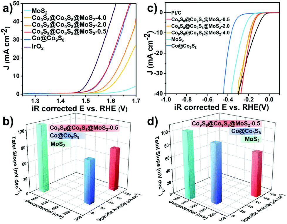 | ||
| Fig. 4 (a) LSV curves of samples for OER in 1 mol L−1 O2-saturated KOH; (b) relationship between Tafel slope, overpotential for 10 mA cm−2 and specific activity for OER; (c) LSV curves of samples for HER in 1 mol L−1 N2-saturated KOH and (d) relationship between Tafel slope, overpotential for 10 mA cm−2 and specific activity for HER. (The Loading mass of samples were all 0.20 mg cm−2.) | ||
Encouraged by the outstanding activity of the HER and OER, we further investigated the ORR activity of Co9S8@Co9S8@MoS2-0.5 and other contrast samples in 0.1 mol L−1 KOH solution. As shown in Fig. S17,† the behavior of Co9S8@Co9S8@MoS2-0.5 in cyclic voltammetry (CV) was assessed by using a three-electrode system in an O2- or N2-saturated 0.1 mol L−1 KOH solution. Co9S8@Co9S8@MoS2-0.5 exhibits a distinct peak in the O2 saturated electrolyte, showing a high activity for the ORR.33 Linear sweep voltammetry (LSV) polarization curves of the samples were obtained using the rotating disk electrode (RDE) technique at 1600 rpm with a sweep rate of 10 mV s−1. Fig. 5a shows the polarization curves. Co9S8@Co9S8@MoS2-0.5 exhibits a relatively high diffusion-limiting current density (4.76 mA cm−2 at 0.6 V vs. RHE) and half-potential (0.776 V), which are close to those of commercial Pt/C (diffusion-limiting current density of 6.37 mA cm−2 and a half-potential of 0.835 V). As shown in Fig. S18 and S19,† the ORR performance of Co9S8@Co9S8@MoS2-0.5 is also better than Co9S8@Co9S8, MoS2, Co9S8@Co9S8@MoS2-2.0, Co9S8@Co9S8@MoS2-4.0 and CCM-x-mix (x = 0.5, 2.0 and 4.0). The LSV polarization curves of Co9S8@Co9S8@MoS2-0.5, tested at different rotation speeds from 400 to 1600 rpm, demonstrate its rotation-dependent current density (Fig. 5b). Fig. S20† shows the Koutecky–Levich (K–L) plots (J−1vs. ω−1/2) calculated from the above-obtained LSV curves in Fig. 5b, which present good linearity and parallelism, suggesting the first-order reaction kinetics with respect to the dissolved oxygen concentration.34,35 To identify the ORR mechanism of Co9S8@Co9S8@MoS2-0.5, we subsequently performed the rotating ring-disk electrode (RRDE) test at 1600 rpm. The two-electron pathway of the ORR reduces oxygen to peroxide and then to water, whereas the peroxide produced from the two-electron pathway is detrimental to fuel cells. Based on the RRDE measurements, the number of electrons transferred in Co9S8@Co9S8@MoS2-0.5 is nearly 4 (Fig. 5c), suggesting that the pre-catalyst proceeds via a four-electron pathway.31 Furthermore, the yield of HO2− is less than 6% during the ORR. Moreover, the chronoamperometric response confirms the great durability of Co9S8@Co9S8@MoS2-0.5 because it retains a cathodic current of 89% after 12 h. Under the same test conditions, Pt/C retains only 42% (Fig. S17†). A methanol crossover test was carried out during the chronoamperometric response at 0.6 V vs. RHE. As shown in Fig. 5d, Co9S8@Co9S8@MoS2-0.5 is not sensitive to methanol. By contrast, Pt/C is greatly affected by methanol and shows a significant decrease in the current density after the introduction of methanol. The above results indicate that Co9S8@Co9S8@MoS2-0.5 is also a promising ORR pre-catalyst candidate in direct methanol fuel cells.
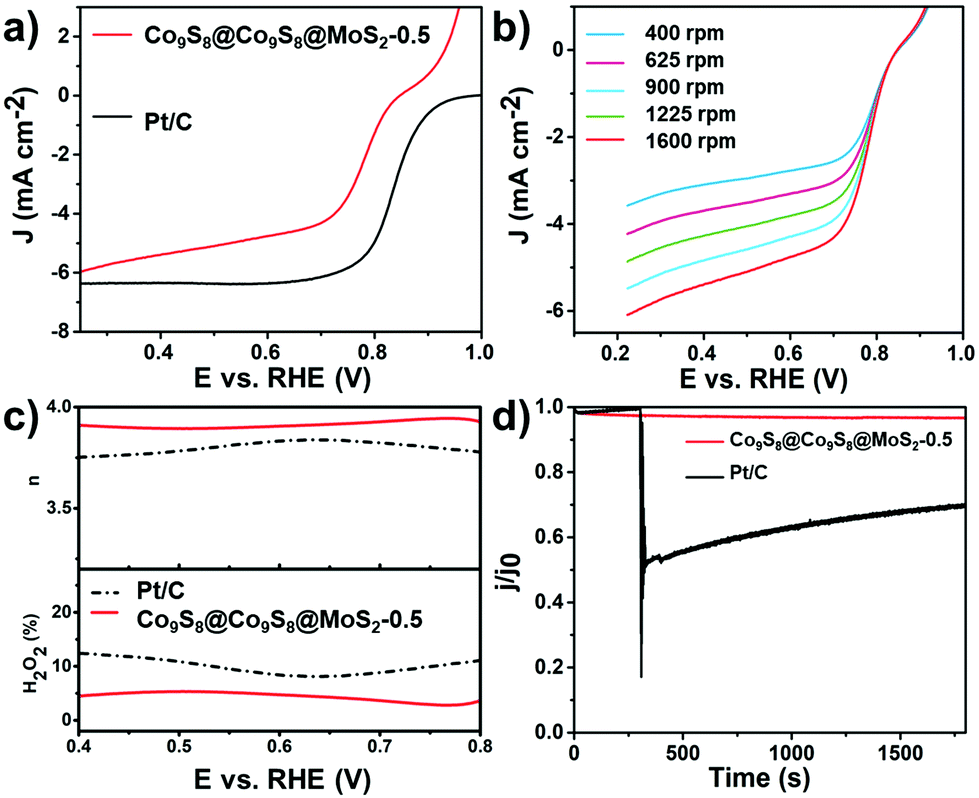 | ||
| Fig. 5 (a) RDE polarization curves of Co9S8@MoS2-0.5 and Pt/C tested in O2-saturated 0.1 mol L−1 KOH with a sweep rate of 10 mV s−1 at 1600 rpm; (b) RDE polarization curves of Co9S8@Co9S8@MoS2-0.5 with rotating rates from 400 to 1600 rpm of 10 mV s−1; (c) electron transfer number (n) at the top and H2O2 yield at the bottom vs. potential; (d) methanol crossover effect test of Co9S8@Co9S8@MoS2-0.5 and Pt/C. (The loading mass was 0.20 mg cm−2 of Pt/C and 0.40 mg cm−2 for other samples.) | ||
Conclusions
In summary, a novel core–double shell heterostructure Co9S8@Co9S8@MoS2-0.5 with tri-functional electrocatalytic activity for the HER, OER and ORR was constructed by two main steps. Firstly, the core–shell structure of the precursor Co@Co9S8 was prepared by sulfurization followed by the pyrolysis of ZIF-67. Then the MoS2 grew on the Co@Co9S8 precursor surface under hydrothermal conditions. The Co@Co9S8 precursor provides abundant basic space to confine the growth of MoS2, which greatly prevents the aggregation of MoS2 and improves the conductivity of the nanostructure. Benefiting from the intriguing synthesis strategy and well-controlled structure, the core–double shell Co9S8@Co9S8@MoS2-0.5 heterostructure exhibits synergistic interaction between Co9S8 and MoS2 and a modified electronic structure. These features enable Co9S8@Co9S8@MoS2-0.5 to show outstanding electrocatalytic performance, i.e., Co9S8@Co9S8@MoS2-0.5 requires an overpotential of 173 mV and 340 mV at 10 mA cm−2 for the HER and OER in alkaline solution, respectively. Besides, the ORR performance with a half-wave potential of 0.77 V and a diffusion-limiting current density of 4.76 mA cm−2 at 0.6 V (vs. RHE) is also obtained. We believe that this work will not only provide creative views for facile synthesis of novel heterostructure materials, but also pave the way for exploring multifunctional electrocatalysts.Conflicts of interest
There are no conflicts to declare.Acknowledgements
This work was financially supported by the NSFC (No. 21671077, 21771075, 21571176, and 21871106). We thank Dr Xiyang Wang, Jilin University, for XANES spectra analysis.Notes and references
- S. Jin, J. M. Kevin, A. G. Hubert, B. G. John and S.-H. Yang, Science, 2011, 334, 1383–1385 CrossRef.
- V. Yarlagadda, M. K. Carpenter, T. E. Moylan, R. S. Kukreja, R. Koestner, W. Gu, L. Thompson and A. Kongkanand, ACS Energy Lett., 2018, 3, 618–621 CrossRef CAS.
- M. Zhang, Q. Dai, H. Zheng, M. Chen and L. Dai, Adv. Mater., 2018, 30, 1705431–1705441 CrossRef.
- X.-Y. Yang, J.-J. Xu, Z.-W. Chang, D. Bao, Y.-B. Yin, T. Liu, J.-M. Yan, D.-P. Liu, Y. Zhang and X.-B. Zhang, Adv. Energy Mater., 2018, 8, 1702242–1702249 CrossRef.
- Z. Yang, C. Zhao, Y. Qu, H. Zhou, F. Zhou, J. Wang, Y. Wu and Y. Li, Adv. Mater., 2019, 31, 1808043–1808051 CrossRef.
- J. Yu, Y. Guo, S. She, S. Miao, M. Ni, W. Zhou, M. Liu and Z. Shao, Adv. Mater., 2018, 30, 1800047–1800057 CrossRef.
- C. Tang, L. Zhong, B. Zhang, H. F. Wang and Q. Zhang, Adv. Mater., 2018, 30, 1705110–1705118 CrossRef.
- X. Zhao, B. Pattengale, D. Fan, Z. Zou, Y. Zhao, J. Du, J. Huang and C. Xu, ACS Energy Lett., 2018, 3, 2520–2526 CrossRef CAS.
- W. Zhou, D.-D. Huang, Y.-P. Wu, J. Zhao, T. Wu, J. Zhang, D.-S. Li, C. Sun, P. Feng and X. Bu, Angew. Chem., Int. Ed., 2019, 58, 4227–4231 CrossRef CAS.
- F. Q. Liu, J. W. Liu, Z. Gao, L. Wang, X.-Z. Fu, L. X. Yang, Y. Tao, W. H. Yin and F. Luo, Appl. Catal., B, 2019, 258, 117973–117981 CrossRef CAS.
- H. He, J. Lin, W. Fu, X. Wang, H. Wang, Q. Zeng, Q. Gu, Y. Li, C. Yan, B. K. Tay, C. Xue, X. Hu, S. T. Pantelides, W. Zhou and Z. Liu, Adv. Energy Mater., 2016, 6, 1600464–1600471 CrossRef.
- L. Ma, Y. Hu, G. Zhu, R. Chen, T. Chen, H. Lu, Y. Wang, J. Liang, H. Liu, C. Yan, Z. Tie, Z. Jin and J. Liu, Chem. Mater., 2016, 28, 5733–5742 CrossRef CAS.
- X. Zhang, S. Liu, Y. Zang, R. Liu, G. Liu, G. Wang, Y. Zhang, H. Zhang and H. Zhao, Nano Energy, 2016, 30, 93–102 CrossRef CAS.
- J. Li, G. Li, J. Wang, C. Xue, Y. Zhang, X. Wu, L. Meng and L. Li, Eur. J. Inorg. Chem., 2019, 19, 2448–2454 CrossRef.
- J. Yang, G. Zhu, Y. Liu, J. Xia, Z. Ji, X. Shen and S. Wu, Adv. Funct. Mater., 2016, 26, 4712–4721 CrossRef CAS.
- T. Chen and Y. Tan, Nano Res., 2018, 11, 1331–1344 CrossRef CAS.
- J. Zhou, Y. Dou, A. Zhou, R.-M. Guo, M.-J. Zhao and J.-R. Li, Adv. Energy Mater., 2017, 7, 1602643–1602653 CrossRef.
- J. Wang, L. Li, L. Wang, Y. Liu, W. Sun, W. Li and G. Li, ACS Omega, 2018, 3, 464–471 CrossRef CAS.
- M. R. Gao, J. X. Liang, Y. R. Zheng, Y. F. Xu, J. Jiang, Q. Gao, J. Li and S. H. Yu, Nat. Commun., 2015, 6, 5982–5989 CrossRef CAS.
- R. Wu, X. Qian, X. Rui, H. Liu, B. Yadian, K. Zhou, J. Wei, Q. Yan, X. Q. Feng, Y. Long, L. Wang and Y. Huang, Small, 2014, 10, 1932–1938 CrossRef CAS.
- L.-L. Feng, M. Fan, Y. Wu, Y. Liu, G.-D. Li, H. Chen, W. Chen, D. Wang and X. Zou, J. Mater. Chem. A, 2016, 4, 6860–6867 RSC.
- J. Wang, C. Luo, T. Gao, A. Langrock, A. C. Mignerey and C. Wang, Small, 2015, 11, 473–481 CrossRef CAS.
- H. Li, X. Qian, C. Xu, S. Huang, C. Zhu, X. Jiang, L. Shao and L. Hou, ACS Appl. Mater. Interfaces, 2017, 9, 28394–28405 CrossRef CAS.
- L. L. Feng, G. D. Li, Y. Liu, Y. Wu, H. Chen, Y. Wang, Y. C. Zou, D. Wang and X. Zou, ACS Appl. Mater. Interfaces, 2015, 7, 980–988 CrossRef CAS.
- S. V. Didziulis, J. R. Lince, D. K. Shuh, T. D. Durbin and J. A. Yarmoff, J. Electron Spectrosc., 1992, 60, 175–192 CrossRef CAS.
- M. Kasrai, M. E. Fleet, T. K. Sham and G. M. Bancroft, Solid State Commun., 1988, 68, 507–511 CrossRef CAS.
- D. Liu, W. Xu, Q. Liu, Q. He, Y. A. Haleem, C. Wang, T. Xiang, C. Zou, W. Chu, J. Zhong, Z. Niu and L. Song, Nano Res., 2016, 9, 2079–2087 CrossRef CAS.
- B. Sonntag and F. C. Brown, Phys. Rev. B: Solid State, 1974, 10, 2300–2306 CrossRef CAS.
- X. Wang, K. Huang, L. Yuan, S. Xi, W. Yan, Z. Geng, Y. Cong, Y. Sun, H. Tan, X. Wu, L. Li and S. Feng, J. Phys. Chem. Lett., 2018, 9, 4146–4154 CrossRef CAS.
- L. C. Seitz, C. F. Dickens, K. Nishio, Y. Hikita, J. Montoya, A. Doyle, C. Kirk, A. Vojvodic, H. Y. Hwang, J. K. Norskov and T. F. Jaramillo, Science, 2016, 353, 1011–1014 CrossRef CAS.
- N. Cheng, S. Stambula, D. Wang, M. N. Banis, J. Liu, A. Riese, B. Xiao, R. Li, T. K. Sham, L. M. Liu, G. A. Botton and X. Sun, Nat. Commun., 2016, 7, 13638–13647 CrossRef CAS.
- J. Wang, L. Li, H. Tian, Y. Zhang, X. Che and G. Li, ACS Appl. Mater. Interfaces, 2017, 9, 7100–7107 CrossRef CAS.
- H. Li, Q. Li, P. Wen, T. B. Williams, S. Adhikari, C. Dun, C. Lu, D. Itanze, L. Jiang, D. L. Carroll, G. L. Donati, P. M. Lundin, Y. Qiu and S. M. Geyer, Adv. Mater., 2018, 30, 1705796–1705804 CrossRef.
- P. Yin, T. Yao, Y. Wu, L. Zheng, Y. Lin, W. Liu, H. Ju, J. Zhu, X. Hong, Z. Deng, G. Zhou, S. Wei and Y. Li, Angew. Chem., Int. Ed., 2016, 55, 10800–10805 CrossRef CAS.
- J. Guo, Zh. Mao, X. i Yan, R. Su, P. Guan, B. Xu, X. Zhang, G. Qin and S. J. Pennycook, Nano Energy, 2016, 28, 261–268 CrossRef CAS.
Footnote |
| † Electronic supplementary information (ESI) available. See DOI: 10.1039/c9qi01080g |
| This journal is © the Partner Organisations 2020 |