Open Access Article
This Open Access Article is licensed under a
Creative Commons Attribution 3.0 Unported Licence

Correction: Stabilization of negative capacitance in ferroelectric capacitors with and without a metal interlayer

T. Rollo *a, F. Blanchini b, G. Giordano c, R. Specogna a and D. Esseni *a
aDPIA, University of Udine, Via delle Scienze 206, 33100 Udine, Italy. E-mail: david.esseni@uniud.it
bDMIF, University of Udine, Via delle Scienze 206, 33100 Udine, Italy
cDII, University of Trento, via Sommarive 9, 38123 Povo, TN, Italy

Received 22nd May 2020 , Accepted 22nd May 2020

First published on 2nd June 2020


Abstract

Correction for ‘Stabilization of negative capacitance in ferroelectric capacitors with and without a metal interlayer’ by T. Rollo, et al., Nanoscale, 2020, 12, 6121–6129, DOI: 10.1039/C9NR09470A.


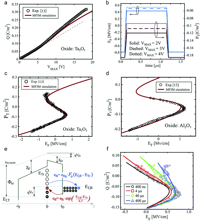
The authors regret that the value of β in the caption of Fig. 4 was incorrectly given as 4.5 × 10⁹ m5 C−2 F−1. The correct value of β is 2.25 × 10¹⁰ m5 C−2 F−1. Fig. 4, along with the full corrected caption, is displayed below.
image file: d0nr90122a-f4.tif
Fig. 4 Comparison between simulations and experiments. Measurements (symbols) and simulations (lines) for the MFIM structures in ref. 12 and 13. For the Hf0.5Zr0.5O2–Ta2O5 capacitor the simulation parameters are εF = 33, εD = 23.48, tF = 11.6 nm, tD = 13.5 nm, α = −4.6 × 10⁸ m F−1, and β = 9.8 × 10⁹ m5 C−2 F−1, while for the Hf0.5Zr0.5O2–Al2O3 system the parameters are εD = 8, tF = 7.7 nm, tD = 4 nm, α = −9.45 × 10⁸ m F−1 and β = 2.25 × 10¹⁰ m5 C−2 F−1;12,13 for both capacitors we used ρ = 0.5 mΩ m and k = 2 × 10⁻⁹ m3 F−1 m−1. (a) Reversibly stored and released charge, Q, versus the top value VMAX of the trapezoidal voltage waveform across the capacitor. (b) Simulated ferroelectric field and charge versus time produced by a trapezoidal input VT with a pulse width of 1 μs and for different VT amplitudes. (c) Polarisation versus ferroelectric electric field for the Hf0.5Zr0.5O2–Ta2O5 MFIM capacitor. (d) Polarisation versus ferroelectric electric field for the Hf0.5Zr0.5O2–Al2O3 capacitor. (e) Sketch of the band structure of the MFIM device with representation of the emission and capture mechanisms. (f) Simulated charge versus ferroelectric EF curves for different pulse widths of the input signal and fixed density NT = 7.512 eV−1 cm−2 of acceptor type interface traps with a uniform energy distribution. In these simulations the emission rate is en0 = 5 × 10⁴ s−1, the metal gate work-function is ΦM = 4.05 eV, and the electron affinity is χF = 2.2 eV for Hf0.5Zr0.5O2 and χD = 3.2 eV for Ta2O5.29

The Royal Society of Chemistry apologises for these errors and any consequent inconvenience to authors and readers.


This journal is © The Royal Society of Chemistry 2020
Click here to see how this site uses Cookies. View our privacy policy here.