 Open Access Article
Structural evolution of CrN nanocube electrocatalysts during nitrogen reduction reaction†
Zili
Ma
 ab,
Jianhong
Chen
b,
Dongbao
Luo
ac,
Thomas
Thersleff
b,
Richard
Dronskowski
 ac and
Adam
Slabon
 *b
*b
aChair of Solid-State and Quantum Chemistry, Institute of Inorganic Chemistry, RWTH Aachen University, 52056 Aachen, Germany
bDepartment of Materials and Environmental Chemistry, Stockholm University, 10691 Stockholm, Sweden. E-mail: adam.slabon@mmk.su.se
cHoffmann Institute of Advanced Materials, Shenzhen Polytechnic, 7098 Liuxian Boulevard, Nanshan District, Shenzhen, China
First published on 9th September 2020
Abstract
Metal nitrides have been suggested as prospective catalysts for the electrochemical nitrogen reduction reaction (NRR) in order to obtain ammonia at room temperature under ambient pressure. Herein, we report that templated chromium nitride porous microspheres built up by nanocubes (NCs) are an efficient noble-metal-free electrocatalyst for NRR. The CrN NCs catalyst exhibits both a high stability and NH3 yield of 31.11 μg h−1 mgcat.−1 with a Faradaic efficiency (FE) of 16.6% in 0.1 M HCl electrolyte. Complementary physical characterization techniques demonstrate partial oxidation of the pristine CrN NCs during reaction. Structural characterization by means of scanning transmission electron microscopy (STEM) combining electron energy loss spectrum (EELS) and energy dispersive X-ray spectroscopy (EDX) analysis reveals the NC structure to consist of an O-rich core and N-rich shell after NRR. This gradient distribution of nitrogen within the CrN NCs upon completed NRR is distinct to previously reported metal nitride NRR catalysts, because no significant loss of nitrogen occurs at the catalyst surface.
Introduction
Shortening of energy supplies combined with an increasing environmental pollution have become the major restriction factors in the sustainable development of human society.1,2 These call for the urgent demand of renewable energy and green synthesis of important chemicals. NH3 is not only a vital chemical substance to medicine, agriculture, and textiles, but also an attractive carbon-neutral energy carrier with high-energy density.3,4 Today, NH3 synthesis is dominated by the industrial Haber–Bosch process, which is usually performed at high temperature and pressure with heavy energy consumption.5,6 Additionally, the high emission of CO2 that are inevitable connected with the Haber–Bosch process force the chemical industry to search for carbon-neutral alternatives with respect to legislative regulations on CO2 emission trading certificates.7,8Reducing N2 to NH3 in aqueous systems under ambient conditions and an external voltage, i.e. electrocatalytic NRR, has been identified as a potential feasible solution by theoretical studies and previous experimental work.9,10 During the NRR, NH3 is produced by activation of atmospheric nitrogen and by using water molecules as the hydrogen source.11,12 However, its practical application is still hindered by various factors, such as the low NH3 generation rate and low Faradaic efficiency (FE) values. An efficient catalyst for the NRR is required in order to overcome large overpotential due to the strongly covalent N![[triple bond, length as m-dash]](https://www.rsc.org/images/entities/char_e002.gif) N bonds and poor polarizability of the N2 molecule.13 It is therefore crucial to develop an electrocatalyst that combines high FE with sufficient stability. During the last few years, numerous materials have been investigated as potential electrocatalysts for NRR under ambient conditions in aqueous solutions.14–16 Among the two typical NRR electrocatalysts, i.e. homogeneous and heterogeneous entities, the latter is more beneficial with respect to lower cost, higher durability and easier integration with electrode support materials.17 The most investigated noble-metal catalysts, such as Pt and Rh, are naturally limited due their scarcity, high price and the strong competitive reaction of hydrogen evolution reaction (HER).18 It has been proven theoretically and experimentally that a relatively strong interaction with N2 as well as a weak binding to intermediate species, in combination with a relatively low proton adsorption ability to suppress the competing HER, is essential for a NRR electrocatalyst.19
N bonds and poor polarizability of the N2 molecule.13 It is therefore crucial to develop an electrocatalyst that combines high FE with sufficient stability. During the last few years, numerous materials have been investigated as potential electrocatalysts for NRR under ambient conditions in aqueous solutions.14–16 Among the two typical NRR electrocatalysts, i.e. homogeneous and heterogeneous entities, the latter is more beneficial with respect to lower cost, higher durability and easier integration with electrode support materials.17 The most investigated noble-metal catalysts, such as Pt and Rh, are naturally limited due their scarcity, high price and the strong competitive reaction of hydrogen evolution reaction (HER).18 It has been proven theoretically and experimentally that a relatively strong interaction with N2 as well as a weak binding to intermediate species, in combination with a relatively low proton adsorption ability to suppress the competing HER, is essential for a NRR electrocatalyst.19
To date, transition-metal oxides (TMOs) such as WO3,20 Ta2O5![[thin space (1/6-em)]](https://www.rsc.org/images/entities/char_2009.gif) 21 and CeO2
21 and CeO2![[thin space (1/6-em)]](https://www.rsc.org/images/entities/char_2009.gif) 22 containing metal ions with noble-gas electronic shells have been broadly applied as electrocatalysts for NRR under ambient conditions because of their availability.23 However, the unfavorable adsorption of N2 due to their electron-rich surface and low FE due to poor conductivity is hindering their application severely.24 Thus, research has been devoted to other non-oxide transition-metal-based materials to find new candidates for the NRR, such as 2D MXenes,25 metal carbides,26 metal complexes in nitrogen-doped carbon,27 metal sulphides,28 metal nitrides,29–32 metal hydrides,33 metal halogens34 and perovskite oxynitride-hydrides.35 Besides that, the metal-free carbon nitride also has been proposed.36 Among them, recent theoretical calculations10,37 and experimental results30,31 have proposed that transition-metal nitrides are promising electrocatalyst candidates for NRR, operating via the Mars-van Krevelen (MvK) mechanism under ambient conditions. The key feature of Mvk mechanism is the substitution and exchange of atoms from the catalyst's lattice by the adsorbed reactants, forming consequently the product which contains the elements from both the feed reactants and the catalyst. Scheme 1 illustrates one possible pathway of the MvK mechanism for the NRR over transition-metal nitride electrocatalysts.30,31
22 containing metal ions with noble-gas electronic shells have been broadly applied as electrocatalysts for NRR under ambient conditions because of their availability.23 However, the unfavorable adsorption of N2 due to their electron-rich surface and low FE due to poor conductivity is hindering their application severely.24 Thus, research has been devoted to other non-oxide transition-metal-based materials to find new candidates for the NRR, such as 2D MXenes,25 metal carbides,26 metal complexes in nitrogen-doped carbon,27 metal sulphides,28 metal nitrides,29–32 metal hydrides,33 metal halogens34 and perovskite oxynitride-hydrides.35 Besides that, the metal-free carbon nitride also has been proposed.36 Among them, recent theoretical calculations10,37 and experimental results30,31 have proposed that transition-metal nitrides are promising electrocatalyst candidates for NRR, operating via the Mars-van Krevelen (MvK) mechanism under ambient conditions. The key feature of Mvk mechanism is the substitution and exchange of atoms from the catalyst's lattice by the adsorbed reactants, forming consequently the product which contains the elements from both the feed reactants and the catalyst. Scheme 1 illustrates one possible pathway of the MvK mechanism for the NRR over transition-metal nitride electrocatalysts.30,31
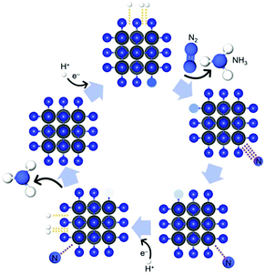 | ||
| Scheme 1 Schematic illustration of possible pathway of MvK mechanism for NRR reaction over transition-metal nitride electrocatalysts. In the first step, N2 is being adsorbed on the CrN surface while the NH3 molecule, which was formed in the previously completed catalytic cycle, desorbs from the catalyst's surface.30,31 | ||
The electrode–electrolyte interface is the key parameter for NH3 electrosynthesis due to N2 activation and the competing HER.38 The majority of non-noble metal catalysts undergo significant chemical changes during NRR, such as partial substitution of the anion (e.g. VN to VOxNy![[thin space (1/6-em)]](https://www.rsc.org/images/entities/char_2009.gif) 30) or loss of nitrogen (e.g. conversion of CrN to Cr2N
30) or loss of nitrogen (e.g. conversion of CrN to Cr2N![[thin space (1/6-em)]](https://www.rsc.org/images/entities/char_2009.gif) 31). It should be noted that Simonov et al. reported that VN is not active for the NRR and that the formed NH3 is due to loss of surface nitrogen of the catalyst; i.e. leaving a stable nitride core and a mixed nitride-oxide shell upon electrochemical operation.3915N isotope experiments have revealed that VN reduces nitrogen via the MvK mechanism. Further quantitative 14N/15N isotope-exchange experiments determined the density of active surface N atoms on the vanadium nitride electrocatalyst for NRR.40 Accordingly, metal nitride electrocatalysts should display a stable nitride core and a mixed nitride-oxide shell upon electrochemical operation conditions for NRR. However, the N/O distribution over these metal nitride particles, which is essential for universal metal nitrides, remains still unclear.
31). It should be noted that Simonov et al. reported that VN is not active for the NRR and that the formed NH3 is due to loss of surface nitrogen of the catalyst; i.e. leaving a stable nitride core and a mixed nitride-oxide shell upon electrochemical operation.3915N isotope experiments have revealed that VN reduces nitrogen via the MvK mechanism. Further quantitative 14N/15N isotope-exchange experiments determined the density of active surface N atoms on the vanadium nitride electrocatalyst for NRR.40 Accordingly, metal nitride electrocatalysts should display a stable nitride core and a mixed nitride-oxide shell upon electrochemical operation conditions for NRR. However, the N/O distribution over these metal nitride particles, which is essential for universal metal nitrides, remains still unclear.
Herein, we report on CrN nanocube (NC) electrocatalysts and the observation of an unexpected structural feature during NRR. CrN NCs exhibit an core–shell structure with a nitrogen-rich surface and an oxygen-rich core during NRR; as evidenced by Scanning Transmission Electron Microscopy (STEM) including Electron Energy Loss spectroscopy (EELS) and Energy Dispersive X-ray Spectroscopy (EDX).
Experimental section
Preparation of CrN NCs
A glucose-assisted hydrothermal synthesis followed by nitridation was employed to grow CrN NCs (Scheme 2). Briefly, 1 mmol CrCl3·6H2O (Merck, extra pure) and 25 mmol glucose monohydrate (Grüssing GmbH) were dissolved in 40 ml distilled water by stirring to obtain a clear solution. 10 ml of the solution were added to a 20 mL stainless steel autoclave. The autoclave was sealed and heated at 453 K for 12 h.41 After the reaction, the autoclave was cooled down to room temperature. The black product was collected and washed with deionized water and ethanol and dried at 333 K for overnight. Then the dried sample was annealed at 773 K for 4 h to obtain Cr2O3 microspheres which consist of nanoparticles. Black CrN NCs were obtained by nitridation under flow of NH3 (15 mL min−1) and H2 (5 mL min−1) at 1123 K for 8 h.42 For comparison, pristine CrN was also obtained by nitridation of commercially-available Cr2O3 for comparison. | ||
| Scheme 2 Schematic illustration of the synthetic procedure for the CrN NCs. Glucose is used as template for preparation of microspheres with an inherent porous structure formed by NCs. | ||
Structural characterization
Powder X-ray diffraction (XRD) patterns were recorded on a STOE STADI-P diffractometer (Cu Kα1 radiation) equipped with a DECTRIS Mythen 1 K detector in transmission mode. Scanning electron microscopy (SEM) images were acquired using a Zeiss/LEO 1530. High-resolution transmission electron microscopy (HR-TEM) was conducted on a Themis Z TEM (Thermo Fisher). Electron energy loss spectrum was obtained in scanning transmission electron microscopy (STEM) mode.Working electrode preparation
Carbon paper (CP) (QuinTech) was washed with deionized water and ethanol for 30 min by sonication. The homogeneous electrocatalyst ink was prepared by dispersing 6 mg CrN NCs in 30 μL of Nafion D-520 dispersion solution (Sigma-Aldrich, 5 wt%) and 970 μL of absolute ethanol by sonicating for 1 h. 20 μL electrocatalyst ink was loaded onto the pre-cleaned carbon paper with area of 1 × 1 cm2 and dried under ambient condition.Determination of ammonia
The NH3 concentrations were determined at 655 nm by means a 20 Genesys spectrophotometer (Spectronic Instruments) using a one-centimeter quartz cuvette and MColortest Ammonium Test kits (Merck, 114750). The standard concentration-absorbance curve was calibrated using the standard NH4Cl solution with NH3 concentrations of 0.0, 0.05, 0.10, 0.15, 0.20, 0.25 and 0.30 μg mL−1 in 0.1 M HCl. Typically, 4500 μL standard solution was mixed with 450 μL 1 M NaOH (Th. Geyer GmbH) to adjust the pH within the required range 4–13. Then, 0.4 mL reagent NH4-1 and 1 level microspoon reagent NH4-2 were added the above solution under vigorously shaking until the reagent dissolved completely. After waiting 5 min, four drops of reagent NH4-3 were added. The distilled water was used as the blank sample. The absorbance was measured at 655 nm after exactly 7 min. The fitting curve Fig. S1† (y = 0.4293x + 0.0589, R2 = 0.997) showed a good linear relation of absorbance value with the NH3 concentration. 4500 μL electrolyte was removed from the cathodic chamber for NH3 determination according this procedure. The NH3 yield rate and Faradaic efficiency (FE) were calculated using the following equation:where cNH3 is the measured concentration of NH3, V is the volume of the cathodic reaction electrolyte, t is the reaction time, mcat. is the mass of catalyst loaded on the working electrode, F is the Faraday constant and Q is the total charge used for the electrodes.
Determination of N2H4
The N2H4 concentrations were determined at 455 nm by means a 20 Genesys spectrophotometer (Spectronic Instruments) using a one-centimeter quartz cuvette and Hydrazine Test kits (Merck, 109711). The standard concentration-absorbance curve was calibrated using the standard N2H4·H2SO4 solution with N2H4 concentrations of 0.00, 0.20, 0.40, 0.60, 0.80 and 1.00 μg mL−1 in 0.1 M HCl. Typically, 2300 μL standard solution was mixed with 230 μL 1 M NaOH (Th. Geyer GmbH) to adjust the pH within the required range 2–10 according the test kit manual. Then, 1.0 mL reagent Hy-1 was mixed with the above solution. The distilled water was used as the blank sample. The absorbance was measured at 455 nm after exactly 5 min. The fitting curve Fig. S2† (y = 1.1151x + 0.0104, R2 = 0.999) showed a good linear relation of absorbance value with the N2H4 concentration. 2300 μL electrolyte was removed from the cathodic chamber for N2H4 determination according the above procedure.Electrochemical measurements
The two-compartment cell (Fig. S3†) separated by a Nafion 117 membrane was used for electrochemical NRR experiments. The electrolyte in the anode and cathode chamber were 50 mL 0.1 M HCl for each compartment. Electrochemical measurements were performed under ambient conditions in a three-electrode setup with an Interface 1010T Workstation (Gamry, USA). A graphite rod and a 1 M Ag/AgCl electrode were used as counter and reference electrodes, respectively. The carbon paper with or without sample were used as working electrode. All current values were recorded versus 1 M Ag/AgCl and converted to the reversible hydrogen electrode (RHE) according to ERHE (V) = EAg/AgCl + (0.059 × pH) + EθAg/AgCl, and the presented current density was normalized to the geometric surface area. Before collecting data, the working electrodes were subject for chronoamperometry (CA) at −0.5 V vs. RHE for two hours under N2 bubbling. Polarization curves were obtained using linear sweep voltammetry (LSV) with a scan rate of 5 mV s−1 in 0.1 M HCl solution, which was purged with N2 or Ar for 40 min before the measurement. Before all NRR measurements, fresh electrolyte was purged with N2 for 30 min. CA measurements were carried out in N2-saturated 0.1 M HCl solution with continuous N2 bubbling. For comparison, CA measurements in Ar-saturated 0.1 M HCl solution with continuous Ar bubbling were also conducted.Computational methods
The Vienna Ab initio Simulation Package (VASP)43 based on density-functional theory and the projector augmented wave (PAW)44,45 method was used to optimize the structures, also including a dispersion correction (DFT-D3).46 The exchange–correlation functional was described by the generalized-gradient approximation (GGA) as envisioned by Perdew–Burke–Ernzerhof (PBE).47 A plane-wave basis-set cutoff of 600 eV and the Γ-point were found to converge energies to smaller than 0.01 eV per atom. In detail, a cubic Cr63N623+ crystal with a lattice parameter of 4.1668 Å was put into the center of a cubic 26 × 26 × 26 Å3 simulation cell, and the center Cr atom on the [001] plane with fivefold N coordination was approached by an N–N dimer whose outer N atom was allowed to structurally relax.Results and discussion
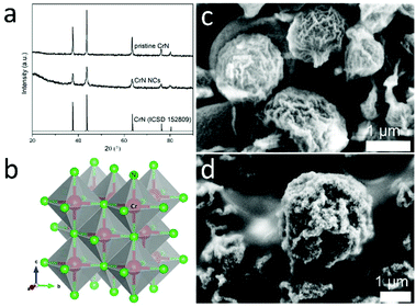
The Cr2O3 microspheres precursors were prepared by a modified glucose-mediated-hydrothermal-calcination route.41 The powder XRD patterns of the synthesized microspheres are presented in Fig. S4,† in accordance with the Cr2O3 standard pattern (ICSD 75577). The CrN NCs were synthesized by nitridation of the as-prepared Cr2O3 microspheres under continuous flow of NH3 and H2. As depicted in Fig. 1, all Bragg peaks can be well indexed to characteristic reflection patterns of CrN (ICSD 152809), revealing a cubic rock-salt structure (Fig. 1b). The complementary bulk CrN were also obtained by nitridation of commercial Cr2O3 for comparison (XRD patterns shown in Fig. 1a). Glucose has been employed as the common mediator to produce hollow metal oxides microspheres due the decomposition of carbon core during the calcination step. The SEM images (Fig. 1) reveal that the surface of the microspheres is roughened and formed by aggregated nanoparticles of the metal oxides/nitrides, inducing an inherent porosity of the shell.48 When comparing the SEM micrographs in Fig. 1c d, more cracks can be observed for CrN NCs than for Cr2O3 particles; a phenomenon generally known when nitridation at higher temperatures is carried out.The carbon paper loaded with the prepared CrN NCs served as cathodic working electrode. The electrocatalytic NRR activity of the sample was evaluated in 0.1 M HCl under ambient conditions in a three-electrode system using a two-compartment cell separated by a Nafion 117 membrane. In the cathode chamber, N2 gas spreads to the electrode surface, providing the possibility to react with protons provided by the electrolyte solution.49 The LSV technique was first carried out to explore the electrocatalytic NRR properties. As presented in Fig. 2, the curves in N2- and Ar-saturated electrolyte have the same shape. It can be seen that the current density in N2-saturated solution is higher than for the Ar-saturated solution at potentials more negative than −0.3 V vs. RHE. This indicates that the CrN NCs are active to catalyze the NRR to NH3.
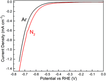 | ||
| Fig. 2 LSV curves of NCs CrN/CP recorded in N2-saturated (red line) and Ar-saturated (black line) 0.1 M HCl. | ||
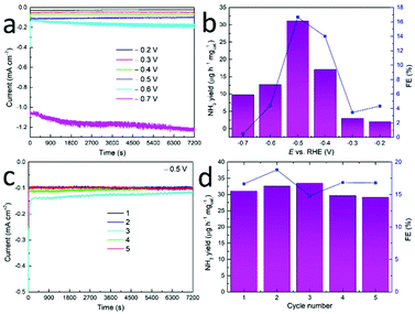
The electrocatalytic NRR experiments at different potentials were performed for 2 h under a continuous N2 stream to the cathode chamber. Fig. 3a depicts that the current density remains stable during CA for CrN NCs at various potentials, denoting its stability for the NRR. No N2H4 was detected at all applied potentials which hints toward the high selectivity for NH3 production. Fig. 3b depicts the corresponding NH3 yields and FEs which were determined via the calibration curves. With the potential being more cathodic, both the NH3 yields and FEs increase and reach the maximum value of 31.11 μg h−1 mgcat.−1 and FE of 16.64% at −0.5 V vs. RHE.
After the applied potential is more cathodic than the volcanic potential, both the NH3 yields and FEs of electrocatalysts begin to decrease considerably. These results might attribute to the competitive hydrogen-evolving process and adsorption of N2 and hydrogen species on the electrode surface.58 Therefore, the optimum potential of −0.5 V vs. RHE was selected for further studies in this system. The NH3 and FE were compared with other catalysts (see Table 1 and Table S1†), suggesting CrN presented comparable performance to other common catalyst but lower than that of a single atom catalyst. One chromium nitride-based material (CrO0.66N0.56) for NRR has been carried out by Shao and co-workers.39 In their work, the NH3 yield of 15.56 μg h−1 mgcat.−1 at a cell voltage of 2.0 V and the highest FE of 6.7% at a cell voltage of 1.8 V has been achieved over an home-made proton exchange membrane electrolyzer, in which chromium oxynitride nanoparticles were used as the electrocatalyst at the cathode side and IrO2 was used as the electrocatalyst at the anode side.
| Catalyst | Electrolyte | NH3 yield | FE(%) | Ref. |
|---|---|---|---|---|
| CrN NCs | 0.1 M HCl | 31.11 μg h−1 mgcat.−1 | 16.64 | This |
| Mo2N | 0.1 M HCl | 78.4 μg h−1 mgcat.−1 | 4.5 | 29 |
| CrO0.66N0.56 | 1 mM H2SO4 | 15.56 μg h−1 mgcat.−1 | 6.7 | 50 |
| AuCo alloy@GO | 0.5 M K2SO4 | 36.68 μg h−1 mgcat.−1 | 22.08 | 51 |
| TiO2/Ti3C2Tx | 0.1 M HCl | 32.17 μg h−1 mgcat.−1 | 16.07 | 52 |
| Carbon nitride | 0.1 M HCl | 8.09 μg h−1 mgcat.−1 | 11.59 | 53 |
| Boron carbide | 0.1 M HCl | 26.57 μg h−1 mgcat.−1 | 15.95 | 54 |
| Au-Ti3C2 | 0.1 M HCl | 30.06 μg h−1 mgcat.−1 | 18.34 | 55 |
| SA-Ag/NC | 0.1 M HCl | 270.9 μg h−1 mgcat.−1 | 21.9 | 56 |
| Co–Nx–C | 0.05 M H2SO4 | 37.6 μg h−1 mgcat.−1 | 17.6 | 57 |
The stability of the CrN NCs during NRR was estimated by means of consecutive recycling tests. Five cycling tests of 2 hours of long-time CA at −0.5 V vs. RHE were carried out in this study. Only a slight decrease in current density was observed after five cycling tests (Fig. 3c). The NH3 yield rate and corresponding FEs of NCs show small changes and no obvious downward trend after reduplicate tests (Fig. 3d), thus implying good catalytic stability for NRR in accordance with previous (oxy)nitrides studies.50,59
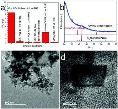
We also compared the NRR performance of the CrN NCs particles with microcrystalline CrN. Fig. 4a evidences that the NH3 yield and FE of CrN NCs at −0.5 V vs. RHE is higher than that of bulk CrN, i.e. approximately 2.9 times larger under the same CA conditions. Possible reasons are the higher concentration of active sites and the diffusion of both reactants and products in the porous structure.41 To further demonstrate the electrocatalytic activity of CrN NCs for NRR, certain control experiments were also carried out: (i) CrN NCs/CP in N2-saturated solution at open circuit potential, (ii) CrN NCs/CP in Ar-saturated solution at −0.5 V vs. RHE, (iii) CrN NCs/CP in air at –0.5 V vs. RHE, (iv) bare CP in N2-saturated solution at −0.5 V vs. RHE and (v) pristine CrN/CP in N2-saturated solution at −0.5 V vs. RHE (see Fig. 4a). During the first four control experiments only negligible NH3 formation was detected. This confirms that the measured amount of NH3 in this work was produced mainly from the NRR process using N2 as the nitrogen source and CrN NCs as the electrocatalyst, because the detected catalytically-produced NH3 amount is significantly higher than the sum from the control experiments.
To understand the reaction process, the CrN NCs were further characterized after a stability test. The recorded powder XRD patterns of the CrN NCs displayed the characteristic reflections for CrN, but with a higher background due to potential amorphization. New Bragg peaks hint toward the formation of a new phase during NRR (Fig. 4b), which is consistent with previous reports on metal nitride NRR electrocatalysts (VN30 and Cr2N31). Particularly, the metal nitrides NRR electrocatalysts have been reported to partially convert to the oxidic or oxynitridic form, providing evidence for the MvK mechanism in NRR reaction. Partially substituting the nitride anion with an oxide anion has been suggested to improve the electronic properties in order to improve the NRR performance. These results have been proven by means of complementary physical characterization techniques and density functional theory (DFT) calculations previously.30
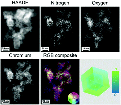
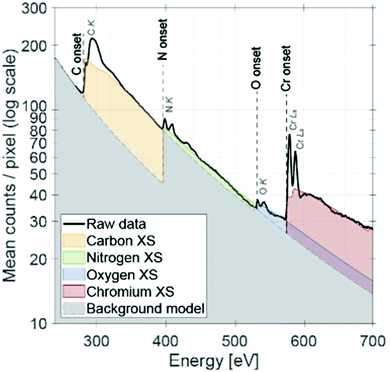
The morphology of the CrN NCs after NRR is shown in the TEM images in Fig. 4c and d. The NCs display particle sizes of approximately 20 nm, and clear lattice fringes can be observed from the HRTEM images. The chemical composition of the CrN NCs after NRR has been analyzed by STEM spectroscopy combining EDX and EELS. Fig. 5 shows the high-angle annular dark field (HAADF) STEM micrograph of the CrN catalyst after NRR and the corresponding elemental abundance maps obtained from EDX spectroscopy. Chromium is distributed homogenously throughout the particles. The elemental correlation map in Fig. 5 shows a striking feature of the NCs after NRR. Instead of forming a nitrogen-rich core as would be initially expected due to the MvK reaction mechanisms, the CrN NCs evidence the opposite structural feature in the form of a nitrogen-rich surface. Although metal nitrides with a higher nitrogen concentration at the surface have been reported previously,60 it should be noted that the CrN have been subject to NRR. Since the latter occurs at metal nitrides via the MvK mechanism, their surface composition contains oxide anions that substitute nitride anions due to nitrogen leaching.30,31,40,61
For the CrN NCs, a possible explanation would be the leaching of the nitrogen atoms upon application of a cathodic current under NRR conditions and a rapid re-nitridation cycle which only occurs at the surface40 and does not proceed to the core of the NCs. The result is a gradient distribution of nitrogen atoms along the whole diameter of the CrN NC. Chang et al. have proposed that a metal oxynitride shell could increase the NRR performance by π backdonation from a delocalized electron environment for nitrogen absorption and activation.24 For the CrN NCs, an average ratio of Cr![[thin space (1/6-em)]](https://www.rsc.org/images/entities/char_2009.gif) :
:![[thin space (1/6-em)]](https://www.rsc.org/images/entities/char_2009.gif) N
N![[thin space (1/6-em)]](https://www.rsc.org/images/entities/char_2009.gif) :
:![[thin space (1/6-em)]](https://www.rsc.org/images/entities/char_2009.gif) O was determined to be 2
O was determined to be 2![[thin space (1/6-em)]](https://www.rsc.org/images/entities/char_2009.gif) :
:![[thin space (1/6-em)]](https://www.rsc.org/images/entities/char_2009.gif) 1
1![[thin space (1/6-em)]](https://www.rsc.org/images/entities/char_2009.gif) :
:![[thin space (1/6-em)]](https://www.rsc.org/images/entities/char_2009.gif) 1; although this relation does not distinguish between the bulk and surface concentration. Another possible reason for the oxygen-rich core could be the residual oxygen atoms upon conversion of Cr2O3 to CrN (see Fig. S5†). However, we believe that this does not explain the nitrogen-rich shell after NRR, because one would expect a loss of nitrogen due to the MvK mechanism. Clearly, this is not the case for the CrN NC catalyst.
1; although this relation does not distinguish between the bulk and surface concentration. Another possible reason for the oxygen-rich core could be the residual oxygen atoms upon conversion of Cr2O3 to CrN (see Fig. S5†). However, we believe that this does not explain the nitrogen-rich shell after NRR, because one would expect a loss of nitrogen due to the MvK mechanism. Clearly, this is not the case for the CrN NC catalyst.
Complementary spectroscopic analysis by means of STEM EELS was further performed to confirm the elemental ratio and the oxidation state of Cr (see Fig. 6). Similar elemental ratio was observed as EDX mapping analysis. Based on the qualitative comparison to the literature,62 it is suggested that Cr has an oxidation state of +3. Recently, Jaramillo and co-workers have shown using the example of MoN that the controlled oxygen incorporation into the surface and bulk is a critical parameter to tailor the catalytic performance for the oxygen reduction reaction.63 Our results indicate that a similar case is present for the CrN NCs when being used catalysts for the NRR.
For the elucidation of the interaction between the CrN catalyst and N2 molecule, complementary theoretical analysis at the DFT level has been carried out (Fig. 7). Briefly, a cubic CrN crystal with 125 atoms (vide supra) was applied as model system to investigate the interaction with an approaching N2 molecule. The total-energy minimum results for a N2–Cr distance of about 2.067 Å and indicates that adsorption of N2 on CrN is indeed energetically favored. Still, more sophisticated theoretical investigations are required to address the adsorption mechanism of N2 on the CrN catalyst with respect to different facets in order to model the complete MvK mechanism.
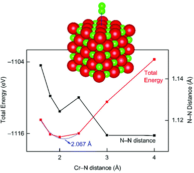 | ||
| Fig. 7 DFT simulation of molecular N2 approaching a cubic chromium nitride crystal, with the total energy given in red and the N–N distance in black. | ||
Conclusions
In summary, we have synthesized CrN microspheres assembled from NCs with inherent porosity and investigated the structure at the nanoscale during NRR. As regards their performance, the catalyst has been tested in 0.1 M HCl electrolyte under ambient conditions, achieving an excellent selectivity and a high NH3 yield of 31.11 μg h−1 mgcat.−1 with a Faradaic efficiency of 16.6% at −0.5 V vs. RHE. Complementary physical characterization techniques demonstrate partial oxidation of the pristine CrN NCs during reaction. Structural characterization by means of EELS and EDX analysis reveals that O-rich core and N-rich shell structure is formed after NRR. This gradient distribution of nitrogen within the CrN catalyst structure upon completed NRR is distinct to previously reported metal nitride NRR catalysts; the latter showing significant loss of nitrogen at the surface. The study not only provides an efficient earth-abundant catalyst for NRR, but also demonstrates the necessity of STEM spectroscopy to understand the critical changes in the chemical nature for metal nitride catalysts at the nanoparticle level. The higher distribution of nitrogen atoms at the surface of the CrN nanocubes, in comparison to its core, indicates that the NRR occurring via the MvK mechanism does not necessarily result in significant substitution of nitrogen atoms with oxygen atoms at the surface during reaction.Conflicts of interest
There are no conflicts to declare.Acknowledgements
Z. M. thanks the China Scholarship Council for a PhD scholarship. T. T. acknowledges support from the Swedish Research Council (project no. 2016-05113). A. S. would like to thank Vinnova, the Swedish innovation agency, for financial support (project: C1Bio 2019-03174). We thank Birgit Hahn for acquiring the SEM images and Dr Istvan Zoltan-Jenei for fruitful discussions.Notes and references
- S. Chu and A. Majumdar, Nature, 2012, 488, 294–303 CrossRef.
- J. G. Chen, R. M. Crooks, L. C. Seefeldt, K. L. Bren, R. M. Bullock, M. Y. Darensbourg, P. L. Holland, B. Hoffman, M. J. Janik, A. K. Jones, M. G. Kanatzidis, P. King, K. M. Lancaster, S. V. Lymar, P. Pfromm, W. F. Schneider and R. R. Schrock, Science, 2018, 360, eaar6611 CrossRef.
- V. Rosca, M. Duca, M. T. de Groot and M. T. M. Koper, Chem. Rev., 2009, 109, 2209–2244 CrossRef.
- C. Liu, K. K. Sakimoto, B. C. Colón, P. A. Silver and D. G. Nocera, Proc. Natl. Acad. Sci. U. S. A., 2017, 114, 6450–6455 Search PubMed.
- P. J. Chirik, Nat. Chem., 2009, 1, 520–522 Search PubMed.
- K. Honkala, Science, 2005, 307, 555–558 CrossRef.
- N. Lazouski, M. Chung, K. Williams, M. L. Gala and K. Manthiram, Nat. Catal., 2020, 3, 463–469 CrossRef.
- C. Ampelli, Nat. Catal., 2020, 3, 420–421 CrossRef.
- Y.-C. Hao, Y. Guo, L.-W. Chen, M. Shu, X.-Y. Wang, T.-A. Bu, W.-Y. Gao, N. Zhang, X. Su, X. Feng, J.-W. Zhou, B. Wang, C.-W. Hu, A.-X. Yin, R. Si, Y.-W. Zhang and C.-H. Yan, Nat. Catal., 2019, 2, 448–456 CrossRef.
- Y. Abghoui, A. L. Garden, V. F. Hlynsson, S. Björgvinsdóttir, H. Ólafsdóttir and E. Skúlason, Phys. Chem. Chem. Phys., 2015, 17, 4909–4918 RSC.
- J. Hou, M. Yang and J. Zhang, Nanoscale, 2020, 12, 6900–6920 Search PubMed.
- G. Qing, R. Ghazfar, S. T. Jackowski, F. Habibzadeh, M. M. Ashtiani, C.-P. Chen, M. R. Smith and T. W. Hamann, Chem. Rev., 2020, 120, 5437–5516 CrossRef.
- S. Gao, Y. Zhu, Y. Chen, M. Tian, Y. Yang, T. Jiang and Z. L. Wang, Mater. Today, 2019, 28, 17–24 CrossRef.
- S. Z. Andersen, V. Čolić, S. Yang, J. A. Schwalbe, A. C. Nielander, J. M. McEnaney, K. Enemark-Rasmussen, J. G. Baker, A. R. Singh, B. A. Rohr, M. J. Statt, S. J. Blair, S. Mezzavilla, J. Kibsgaard, P. C. K. Vesborg, M. Cargnello, S. F. Bent, T. F. Jaramillo, I. E. L. Stephens, J. K. Nørskov and I. Chorkendorff, Nature, 2019, 570, 504–508 CrossRef.
- Y. Song, D. Johnson, R. Peng, D. K. Hensley, P. V. Bonnesen, L. Liang, J. Huang, F. Yang, F. Zhang, R. Qiao, A. P. Baddorf, T. J. Tschaplinski, N. L. Engle, M. C. Hatzell, Z. Wu, D. A. Cullen, H. M. Meyer, B. G. Sumpter and A. J. Rondinone, Sci. Adv., 2018, 4, e1700336 CrossRef.
- A. J. Martín, T. Shinagawa and J. Pérez-Ramírez, Chem, 2019, 5, 263–283 Search PubMed.
- J. Zhao and Z. Chen, J. Am. Chem. Soc., 2017, 139, 12480–12487 Search PubMed.
- C. Li, Y. Fu, Z. Wu, J. Xia and X. Wang, Nanoscale, 2019, 11, 12997–13006 Search PubMed.
- M. Li, H. Huang, J. Low, C. Gao, R. Long and Y. Xiong, Small Methods, 2019, 3, 1800388 CrossRef.
- W. Kong, R. Zhang, X. Zhang, L. Ji, G. Yu, T. Wang, Y. Luo, X. Shi, Y. Xu and X. Sun, Nanoscale, 2019, 11, 19274–19277 RSC.
- W. Fu, P. Zhuang, M. O. Chee, P. Dong, M. Ye and J. Shen, ACS Sustainable Chem. Eng., 2019, 7, 9622–9628 CrossRef CAS.
- H. Xie, H. Wang, Q. Geng, Z. Xing, W. Wang, J. Chen, L. Ji, L. Chang, Z. Wang and J. Mao, Inorg. Chem., 2019, 58, 5423–5427 CAS.
- X. Cui, C. Tang, X. Liu, C. Wang, W. Ma and Q. Zhang, Chem. – Eur. J., 2018, 24, 18494–18501 CAS.
- B. Chang, L. Deng, S. Wang, D. Shi, Z. Ai, H. Jiang, Y. Shao, L. Zhang, J. Shen, Y. Wu and X. Hao, J. Mater. Chem. A, 2020, 8, 91–96 CAS.
- W. Peng, M. Luo, X. Xu, K. Jiang, M. Peng, D. Chen, T. Chan and Y. Tan, Adv. Energy Mater., 2020, 2001364 CAS.
- H. Cheng, L.-X. Ding, G.-F. Chen, L. Zhang, J. Xue and H. Wang, Adv. Mater., 2018, 30, 1803694 CrossRef.
- C. He, Z.-Y. Wu, L. Zhao, M. Ming, Y. Zhang, Y. Yi and J.-S. Hu, ACS Catal., 2019, 9, 7311–7317 CrossRef CAS.
- X. Li, T. Li, Y. Ma, Q. Wei, W. Qiu, H. Guo, X. Shi, P. Zhang, A. M. Asiri, L. Chen, B. Tang and X. Sun, Adv. Energy Mater., 2018, 8, 1801357 CrossRef.
- X. Ren, G. Cui, L. Chen, F. Xie, Q. Wei, Z. Tian and X. Sun, Chem. Commun., 2018, 54, 8474–8477 RSC.
- X. Yang, J. Nash, J. Anibal, M. Dunwell, S. Kattel, E. Stavitski, K. Attenkofer, J. G. Chen, Y. Yan and B. Xu, J. Am. Chem. Soc., 2018, 140, 13387–13391 CrossRef CAS.
- J. Nash, X. Yang, J. Anibal, M. Dunwell, S. Yao, K. Attenkofer, J. G. Chen, Y. Yan and B. Xu, J. Phys. Chem. C, 2019, 123, 23967–23975 CAS.
- J. Zhao, C. Cui, H. Wang, J. Han, X. Zhu and Q. Ge, J. Phys. Chem. C, 2020, 124, 616–624 CAS.
- W. Xu, G. Fan, J. Chen, J. Li, L. Zhang, S. Zhu, X. Su, F. Cheng and J. Chen, Angew. Chem., Int. Ed., 2020, 59, 3511–3516 CrossRef CAS.
- Y. Li, T. Li, X. Zhu, A. A. Alshehri, K. A. Alzahrani, S. Lu and X. Sun, Chem. – Asian J., 2020, 15, 487–489 CrossRef CAS.
- M. Kitano, J. Kujirai, K. Ogasawara, S. Matsuishi, T. Tada, H. Abe, Y. Niwa and H. Hosono, J. Am. Chem. Soc., 2019, 141, 20344–20353 CAS.
- G. Peng, J. Wu, M. Wang, J. Niklas, H. Zhou and C. Liu, Nano Lett., 2020, 20, 2879–2885 CAS.
- Y. Abghoui, A. L. Garden, J. G. Howalt, T. Vegge and E. Skúlason, ACS Catal., 2016, 6, 635–646 CAS.
- L. Hu, Z. Xing and X. Feng, ACS Energy Lett., 2020, 5, 430–436 CAS.
- H.-L. Du, T. R. Gengenbach, R. Hodgetts, D. R. MacFarlane and A. N. Simonov, ACS Sustainable Chem. Eng., 2019, 7, 6839–6850 CrossRef CAS.
- X. Yang, S. Kattel, J. Nash, X. Chang, J. H. Lee, Y. Yan, J. G. Chen and B. Xu, Angew. Chem., Int. Ed., 2019, 131, 13906–13910 CrossRef.
- Y. Zhang, W. Qiu, Y. Ma, Y. Luo, Z. Tian, G. Cui, F. Xie, L. Chen, T. Li and X. Sun, ACS Catal., 2018, 8, 8540–8544 CrossRef CAS.
- Y. Li, L. Gao, J. Li and D. Yan, J. Am. Ceram. Soc., 2004, 85, 1294–1296 CrossRef.
- G. Kresse and J. Furthmüller, Phys. Rev. B: Condens. Matter Mater. Phys., 1996, 54, 11169–11186 CrossRef CAS.
- P. E. Blöchl, Phys. Rev. B: Condens. Matter Mater. Phys., 1994, 50, 17953–17979 CrossRef.
- G. Kresse and D. Joubert, Phys. Rev. B: Condens. Matter Mater. Phys., 1999, 59, 1758–1775 CrossRef CAS.
- S. Grimme, J. Antony, S. Ehrlich and H. Krieg, J. Chem. Phys., 2010, 132, 154104 CrossRef.
- J. P. Perdew, K. Burke and M. Ernzerhof, Phys. Rev. Lett., 1996, 77, 3865–3868 CrossRef CAS.
- M.-M. Titirici, M. Antonietti and A. Thomas, Chem. Mater., 2006, 18, 3808–3812 CrossRef CAS.
- L. Zhang, X. Ji, X. Ren, Y. Luo, X. Shi, A. M. Asiri, B. Zheng and X. Sun, ACS Sustainable Chem. Eng., 2018, 6, 9550–9554 CrossRef CAS.
- Y. Yao, Q. Feng, S. Zhu, J. Li, Y. Yao, Y. Wang, Q. Wang, M. Gu, H. Wang, H. Li, X. Yuan and M. Shao, Small Methods, 2019, 3, 1800324 CrossRef.
- Q. Wang, G. Zheng, S. Hao, X. Liu, J. Zheng, Y. Wang, Z. Su, N. Xu, Y. He, L. Lei and X. Zhang, ACS Sustainable Chem. Eng., 2020, 8, 44–49 CrossRef CAS.
- Y. Fang, Z. Liu, J. Han, Z. Jin, Y. Han, F. Wang, Y. Niu, Y. Wu and Y. Xu, Adv. Energy Mater., 2019, 9, 1803406 CrossRef.
- C. Lv, Y. Qian, C. Yan, Y. Ding, Y. Liu, G. Chen and G. Yu, Angew. Chem., Int. Ed., 2018, 57, 10246–10250 CrossRef CAS.
- W. Qiu, X.-Y. Xie, J. Qiu, W.-H. Fang, R. Liang, X. Ren, X. Ji, G. Cui, A. M. Asiri, G. Cui, B. Tang and X. Sun, Nat. Commun., 2018, 9, 3485 CrossRef.
- D. Liu, G. Zhang, Q. Ji, Y. Zhang and J. Li, ACS Appl. Mater. Interfaces, 2019, 11, 25758–25765 CrossRef CAS.
- Y. Chen, R. Guo, X. Peng, X. Wang, X. Liu, J. Ren, J. He, L. Zhuo, J. Sun, Y. Liu, Y. Wu and J. Luo, ACS Nano, 2020, 14, 6938–6946 CrossRef CAS.
- M. Qin, X. Li, G. Gan, L. Wang, S. Fan, Z. Yin and G. Chen, ACS Sustainable Chem. Eng., 2020, 8, 13430–13439 CrossRef CAS.
- T. Oshikiri, K. Ueno and H. Misawa, Angew. Chem., Int. Ed., 2016, 55, 3942–3946 CrossRef CAS.
- S. Kang, J. Wang, S. Zhang, C. Zhao, G. Wang, W. Cai and H. Zhang, Electrochem. Commun., 2019, 100, 90–95 CrossRef CAS.
- W. Lengauer, Surf. Interface Anal., 1990, 15, 377–382 CrossRef CAS.
- R. Manjunatha, A. Karajić, H. Teller, K. Nicoara and A. Schechter, ChemCatChem, 2020, 12, 438–443 CrossRef CAS.
- T. L. Daulton and B. J. Little, Ultramicroscopy, 2006, 106, 561–573 CrossRef CAS.
- M. E. Kreider, M. B. Stevens, Y. Liu, A. M. Patel, M. J. Statt, B. M. Gibbons, A. Gallo, M. Ben-Naim, A. Mehta, R. C. Davis, A. V. Ievlev, J. K. Nørskov, R. Sinclair, L. A. King and T. F. Jaramillo, Chem. Mater., 2020, 32, 2946–2960 CrossRef CAS.
Footnote |
| † Electronic supplementary information (ESI) available. See DOI: 10.1039/d0nr04981f |
| This journal is © The Royal Society of Chemistry 2020 |


